1
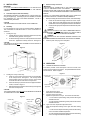
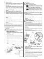
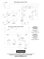
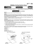
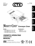
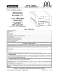
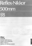
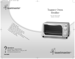
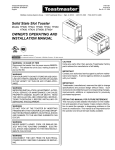
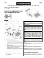
TC2000 English P/N 39629 Price $2.50 Rev. C V1 7/99 Middleby Cooking Systems Group 1400 Toastmaster Drive Elgin, IL 60120 (847)741-3300 FAX (847)741-4406 Conveyor Toaster Oven Model TC2000 OWNER'S OPERATING AND INSTALLATION MANUAL © 1999 Toastmaster, A Middleby Company. is a registered trademark of Toastmaster, A Middleby Company. All rights reserved. I. DESCRIPTION AND SPECIFICATIONS A. Component Location The major components of the toaster oven are shown in Figure 1 below. Figure 1 7. Adjustable draft curtain (2) 3. Upper and Lower temperature adjustment knobs 1. Conveyor speed control knob B. 4. Crumb trays (3) 5. Conveyor end trays (2) Component Function (see Figure 1) 1-3. Oven controls - see Section III, Operation. C. WARNING FOR YOUR SAFETY DO NOT STORE OR USE GASOLINE OR OTHER FLAMMABLE VAPORS OR LIQUIDS IN THE VICINITY OF THIS OR ANY OTHER APPLIANCE 6. Conveyor 2. Power On/Off (I/O) switch 8. Fan WARNING: IN CASE OF FIRE Disconnect the toaster oven from its power source IMMEDIATELY. This allows the unit to cool, making it easier to put out the fire. 4. Crumb trays - Collect crumbs from the food product. One tray is centered under the conveyor, while another is located under each end of the conveyor. All three trays can be removed for cleaning. 5. Conveyor end trays - Provide additional loading/exit space at the ends of the conveyor. 6. Conveyor - Transports the food product through the oven, between the top and bottom heating elements. 7. Adjustable draft curtains - Reduce draft into the oven and prevent heat loss into the environment. 8. Fan - Cools the interior components of the oven. Operating and Electrical Specifications Pre-Heat Time: 10 minutes NOTE Electrical specifications are provided on the wiring diagrams at the back of this Manual. WARNING IMPROPER INSTALLATION, ADJUSTMENT, ALTERATION, SERVICE OR MAINTENANCE CAN CAUSE PROPERTY DAMAGE, INJURY OR DEATH. READ THE INSTALLATION AND OPERATING INSTRUCTIONS THOROUGHLY BEFORE INSTALLING OR SERVICING THIS EQUIPMENT. WARNING DISCONNECT THE TOASTER FROM ITS ELECTRICAL POWER SUPPLY BEFORE CLEANING OR SERVICING. CAUTION Using any parts other than genuine Toastmaster factory parts relieves the manufacturer of all liability. IMPORTANT Contact your authorized service agent to perform maintenance and repairs. A service agency directory is supplied with your toaster oven. IMPORTANT Toastmaster (manufacturer) reserves the right to change specifications and product design without notice. Such revisions do not entitle the buyer to corresponding changes, improvements, additions or replacements for previously purchased equipment. RETAIN THIS MANUAL FOR FUTURE REFERENCE This manual provides detailed information for the installation and operation of your toasteroven. It also contains information to assist the operator in diagnosing problems in the event of a malfunction. This manual is an important tool for the operator and should be kept readily available. II. INSTALLATION C. IMPORTANT IT IS THE CUSTOMERS RESPONSIBILITY TO REPORT ANY CONCEALED OR NON-CONCEALED DAMAGE TO THE FREIGHT COMPANY. IMPORTANT THE ELECTRICAL CONNECTION TO THE OVEN REQUIRES A CIRCUIT BREAKER/FUSED DISCONNECT. ELECTRICAL SPECIFICATIONS ARE LISTED ON THE SERIAL PLATE (SHOWN IN FIGURE 4), AND ON THE WIRING DIAGRAMS AT THE BACK OF THIS MANUAL. A. Installation Options and Kit Availability The installation instructions in this Manual are for a single toaster oven using the supplied legs. A stacking kit (P/N T2114STACK) is available from Toastmaster for 2- and 3-oven stacked installations. This kit includes assembly instructions. CONSULT ALL APPLICABLE NATIONAL AND LOCAL CODES FOR FURTHER ELECTRICAL CONNECTION REQUIREMENTS. 1. CAUTION STACKING MORE THAN THREE OVENS IS NOT PERMITTED. B. Electrical Utility Connection Assembly Before proceeding with the electrical connection, check the following: a. Check that the electrical supply matches the ovens requirements. Refer to the serial plate (Figure 4) and to the electrical specifications on the wiring diagrams at the back of this Manual. b. Check that the appropriate receptacle is available for the power cord plug. If you are installing the oven as part of a stacked installation, REFER TO THE STACKING KIT INSTRUCTIONS or contact Toastmaster for assistance. 1. WARNING ENSURE THAT BOTH THE CIRCUIT BREAKER/FUSED DISCONNECT AND THE POWER ON/OFF (I/O) SWITCH ARE IN THE OFF (O) POSITION BEFORE PROCEEDING. Installing the Legs a. Carefully tilt the oven onto its rear side so that the front (control) side faces directly upwards. See Figure 2. b. Thread the four legs into the four holes provided on the bottom of the oven. Tighten them until they are secure. See Figure 2. WARNING ENSURE THAT ANY PACKING MATERIAL RESIDUE HAS BEEN REMOVED FROM INSIDE THE COOKING CHAMBER. 3. Insert the power cord plug into its receptacle. CAUTION THE SUPPLIED LEGS MUST BE FASTENED IN PLACE PRIOR TO OPERATING THE OVEN. Figure 4 Figure 2 Serial plate III. OPERATION A. Location and Function of Controls This section provides a basic description of the oven controls, their location, and the functions they perform. The operator MUST be familiar with the controls. Refer to Figure 5. 2. Figure 5 Installing the Conveyor End Trays a. Press one of the conveyor end trays down over the end plate of the conveyor frame. See Figure 3. The end tray should extend outward from the end of the conveyor, and its sides should be flush with the sides of the conveyor frame. b. Fasten the end tray in place with one of the supplied 8-32x3/8 screws, as shown in Figure 3. c. Repeat these steps to install the second end tray at the opposite end of the conveyor frame. CAUTION THE CONVEYOR END TRAYS MUST BE FASTENED IN PLACE PRIOR TO OPERATING THE OVEN. Figure 3 1. Position tray 2. Fasten in place with screw Conveyor speed control knob Upper and Lower temperature adjustment knobs Power On/Off (I/O) switch 1. Power On/Off (I/O) switch Switches the oven ON and OFF. 2. Conveyor speed control knob Adjusts the speed of the conveyor. This controls the bake time. 1 is the minimum speed setting, which produces the longest available bake time. 9 is the maximum speed setting, which produces the shortest available bake time. 3-4. Upper and Lower temperature adjustment knobs Adjust the temperature settings of the upper and lower heating zones. 1 is the minimum temperature setting, which sets the heating zone to the lowest available temperature. 9 is the maximum temperature setting, which sets the heating zone to the highest available temperature. B. Operation Procedure 1. Adjust the position of the draft curtains at the ends of the cooking chamber (if necessary). This procedure is described in detail in Section II, Part D, Draft Curtain Adjustment, in this Manual. E. WARNING WHEN CLEANING THE OVEN: IMPORTANT When cooking at very high temperatures (a setting of 8 or higher on either temperature adjustment knob), the oven should be preheated for at least 10 minutes WITH THE DRAFT CURTAINS IN THE FULLY-LOWERED POSITION. After pre-heating, the curtains may be repositioned as required. NEVER USE A CLEANING SOLUTION OTHER THAN SOAP AND WATER ON PORTIONS OF THE OVEN THAT COME INTO CONTACT WITH FOOD PRODUCTS. THESE AREAS INCLUDE THE CONVEYOR BELT AND END TRAYS. 2. Restore electrical power to the oven at the circuit breaker/fused disconnect. 3. Switch the Power On/Off (I/O) Switch to the ON (I) position. 4. Adjust the bake time (if necessary) by turning the conveyor speed control knob. Adjust the upper and lower temperature settings (if necessary) by turning the temperature adjustment knobs. 5. Allow the oven to pre-heat for at least 10 minutes. 6. Load the entrance end of the conveyor with the food product. The motion of the conveyor will move the food product into the cooking chamber. C. Shutdown Procedure 1. Switch the Power On/Off (I/O) switch to the OFF (O) position. 2. Wait for the ovens cooling fan to turn off. 2. Disconnect electrical power to the oven at the circuit breaker/fused disconnect. D. Draft Curtain Adjustment The draft curtains may need to be repositioned to provide adequate clearance for some food products. The curtains should be positioned to prevent drafts into the oven, and heat loss into the environment. NEVER USE PRESSURIZED WATER. NEVER APPLY ENOUGH LIQUID TO STAND IN PLACE ON THE OVEN. LIQUID INSIDE THE OVEN WILL CAUSE A SEVERE ELECTRICAL HAZARD AND MAY OTHERWISE DAMAGE THE OVEN. CAUTION DO NOT clean your oven using abrasive cleaners or pads. Both will scratch and dull the finish. 1. With the conveyor running, use a brush to clean any crumbs off the conveyor into the crumb trays. 2. Switch the Power On/Off (I/O) switch to the OFF (O) position, and wait for the cooling fan to turn off. 3. Disconnect electrical power to the oven at the circuit breaker/fused disconnect. 4. Allow the oven to cool. CAUTION - HOT SURFACES DO NOT TOUCH HOT SURFACES ON THE OVEN, OR REACH INTO THE COOKING CHAMBER, UNTIL THE UNIT HAS COOLED THOROUGHLY. 5. Clean the fan grill on the front of the oven using a stiff nylon brush. 6. Clean the end trays USING SOAP AND WATER ONLY and towel them dry. If necessary, the end trays can be removed for cleaning by removing the screws that hold them in place. See Figure 3 (in Section II). The draft curtains can be removed from the oven to permit the maximum vertical clearance above the conveyor. WARNING BEFORE ADJUSTING THE DRAFT CURTAINS, SWITCH THE POWER ON/OFF SWITCH TO THE OFF (O) POSITION. IMPORTANT If the end trays are removed for cleaning, they must be replaced prior to operating the oven. 7. WHEN REPOSITIONING THE CURTAINS: WEAR A HEAVY OVEN MITT. DO NOT REACH INTO THE OVENS COOKING CHAMBER! See Figure 6. 1. 2. Daily Cleaning Slide the end crumb trays out from underneath the entrance and exit ends of the conveyor. See Figure 7. Figure 7 To reposition the draft curtains: a. Loosen the two screws that hold the draft curtain in place. b. Slide the curtain to the desired clearance above the conveyor. c. Tighten the two screws to hold the curtain in place. d. Repeat these steps for the curtain at the opposite end of the oven. Conveyor Support tab To remove the curtains from the oven: a. Remove the two screws that hold the draft curtain in place. b. Remove the draft curtain. c. Repeat these steps for the curtain at the opposite end of the oven. Figure 6 CAUTION - HOT Screws DO NOT REACH INSIDE COOKING CHAMBER! End crumb trays slide straight out Center tray fits BETWEEN conveyor and support tab. DO NOT insert tray on floor of oven! 8. Lift BOTH ends of the center crumb tray; then, slide the tray out of either end of the oven. 9. Clean all three of the crumb trays using a commercial oven cleaner. If necessary, towel them dry. 10. Replace the center crumb tray in the oven as shown in Figure 7. Draft curtain IMPORTANT Proper positioning of the center crumb tray is REQUIRED for proper cooking. Ensure that the tray is replaced inside the conveyor frame, as shown in Figure 7, and NOT on the floor of the cooking chamber! 11. Replace the two end crumb trays. 12. Clean the outside of the oven using a damp cloth with EITHER soap and water OR a stainless steel cleaner. Use caution to ensure that liquids do not enter the oven during cleaning. Wiring Diagram - Model TC2000 TERMINAL BLOCK CONTACTOR CC FUSE 5A 600V TSTAT N.O. TSTAT N.C. POT 1 1MΩ UPPER TEMP CONTROL TFRMR 230V p 115V s UPPER HEATING ELEMENT FAN POWER ON/OFF (I/O) SWITCH AC CONVEYOR SPEED CONTROLLER POT 2 1MΩ LOWER TEMP CONTROL MOTOR MOTOR FUSE 0.25 A LOWER HEATING ELEMENT Electrical Specifications TC200030 Electrical Schematic - Model TC2000 TSTAT N.O. FAN TSTAT N.C. 208V, 50/60Hz, 1 Ph, 5.0kW, 24A Plug type - NEMA 6-30P C CC FUSE 5A 600V TFRMR 230V p 115V s INPUT UPPER HEATING ELEMENT 240V, 50/60Hz, 1 Ph, 5.3kW, 22.1A CONVEYOR SPEED CONTROLLER OUTPUT Plug type - NEMA 6-15P FUSE 0.25 A POT 1 1MΩ UPPER TEMP CONTROL Electrical Specifications TC200038 CC FUSE 5A 600V MOTOR LOWER HEATING ELEMENT POT 2 1MΩ LOWER TEMP CONTROL A Middleby Company Toastmaster 1400 Toastmaster Drive Elgin, IL 60120 USA (847)741-3300 FAX (847)741-4406 Middleby Corp 24-Hour Service Hotline 1-800-238-8444 www.middleby.com