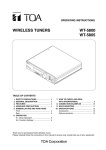
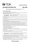
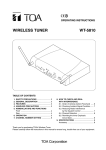
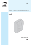
1
OPERATING INSTRUCTIONS
UHF WIRELESS TUNER
AN
T
A
AN
T
B
PE
AK
VO
LU
ME
WT-4820
CH
AN
NE
L
10
AN
TU
NE
R1
T
A
T
B
PE
AK
VO
LU
ME
AN
CH
AN
NE
L
10
TU
N
ER
DIV
ER
2
SIT
YW
IR
O
PO
WE
EL
ES O
ST
UN
E
R
R
WT
-48
20
TABLE OF CONTENTS
1.
2.
3.
4.
5.
SAFETY PRECAUTIONS ........................... 2
GENERAL DESCRIPTION ......................... 3
FEATURES ................................................. 3
HANDLING PRECAUTIONS ...................... 3
NOMENCLATURE AND FUNCTIONS
Front ............................................................ 4
Rear ............................................................. 4
6. INSTALLING THE WTU-4800
TUNER MODULE ....................................... 5
7. PRECAUTIONS ON ANTENNA
INSTALLATION .......................................... 5
8. OPERATION ............................................... 6
9. CONNECTION ............................................ 6
10. INSTALLATION
10.1. Rack Mounting ................................... 7
10.2. Installing the Unit on a Desk ............... 8
11. SPECIFICATIONS ...................................... 8
Accessories ................................................. 8
Please follow the instructions in this manual to obtain the optimum results from this unit.
We also recommend that you keep this manual handy for future reference.
1. SAFETY PRECAUTIONS
• Be sure to read the instructions in this section carefully before use.
• Make sure to observe the instructions in this manual as the conventions of safety symbols and messages
regarded as very important precautions are included.
• We also recommend you keep this instruction manual handy for future reference.
Safety Symbol and Message Conventions
Safety symbols and messages described below are used in this manual to prevent bodily injury and property
damage which could result from mishandling. Before operating your product, read this manual first and
understand the safety symbols and messages so you are thoroughly aware of the potential safety hazards.
WARNING
Indicates a potentially hazardous situation which,
if mishandled, could result in death or serious
personal injury.
When Installing the Unit
• Do not expose the unit to rain or an environment
where it may be splashed by water or other liquids,
as doing so may result in fire or electric shock.
• Use the unit only with the voltage specified on the
unit. Using a voltage higher than that which is
specified may result in fire or electric shock.
• Do not cut, kink, otherwise damage nor modify the
power supply cord. In addition, avoid using the
power cord in close proximity to heaters, and never
place heavy objects -- including the unit itself -- on
the power cord, as doing so may result in fire or
electric shock.
• Avoid installing or mounting the unit in unstable
locations, such as on a rickety table or a slanted
surface. Doing so may result in the unit falling
down and causing personal injury and/or property
damage.
• To prevent lightning strikes, install the unit at least
five meters away from a lightning rod, and yet
within the protective range (angle of 45°) of the
lightning conductor. Lightning strikes may cause a
fire, electric shock or personal injury.
• Since the unit is designed for in-door use, do not
install it outdoors. If installed outdoors, the aging of
parts causes the unit to fall off, resulting in personal
injury. Also, when it gets wet with rain, there is a
danger of electric shock.
2
may cause fire or electric shock.
· If you detect smoke or a strange smell coming
from the unit.
· If water or any metallic object gets into the unit
· If the unit falls, or the unit case breaks
· If the power supply cord is damaged (exposure of
the core, disconnection, etc.)
· If it is malfunctioning (no tone sounds.)
• To prevent a fire or electric shock, never open nor
remove the unit case as there are high voltage
components inside the unit. Refer all servicing to
your nearest TOA dealer.
• Do not place cups, bowls, or other containers of
liquid or metallic objects on top of the unit. If they
accidentally spill into the unit, this may cause a fire
or electric shock.
• Do not touch a plug or antenna during thunder and
lightning, as this may result in electric shock.
CAUTION
Indicates a potentially hazardous situation which,
if mishandled, could result in moderate or minor
personal injury, and/or property damage.
The servicing instructions are for use by qualified
personnel only. To reduce the risk of electric shock
do not perform any servicing other than that
contained in the operating instructions unless you
are qualified to do so. Refer all servicing to qualified
service personnel.
When Installing the Unit
When the Unit is in Use
• Never plug in nor remove the power supply plug
with wet hands, as doing so may cause electric
shock.
• Should the following irregularity be found during
use, immediately switch off the power, disconnect
the power supply plug from the AC outlet and
contact your nearest TOA dealer. Make no further
attempt to operate the unit in this condition as this
• When unplugging the power supply cord, be sure
to grasp the power supply plug; never pull on the
cord itself. Operating the unit with a damaged
power supply cord may cause a fire or electric
shock.
• Avoid installing the unit in humid or dusty locations,
in locations exposed to the direct sunlight, near the
heaters, or in locations generating sooty smoke or
steam as doing otherwise may result in fire or
electric shock.
• When moving the unit, be sure to remove its power
supply cord from the wall outlet. Moving the unit
with the power cord connected to the outlet may
cause damage to the power cord, resulting in fire or
electric shock. When removing the power cord, be
sure to hold its plug to pull.
• Leave the installation of the optional YW-4500
antenna to your TOA dealer because the
installation requires expert knowledge. Improper
installation may cause the antenna to fall, resulting
in personal injury or electric shock.
• The socket-outlet shall be installed near the
equipment and shall be easily accessible. A fire or
electric shock may result.
• Install the AC-DC adapter in well-ventilated
locations. Do not install the adapter in a confined
space such as a book case or similar unit . In
addition, keep over 1 m space above the adapter.
When the Unit is in Use
• Do not place heavy objects on the unit as this may
cause it to fall or break which may result in
personal injury and/or property damage. In
addition, the object itself may fall off and cause
injury and/or damage.
• Make sure that the volume control is set to
minimum position before power is switched on.
Loud noise produced at high volume when power is
switched on can impair hearing.
• Use the dedicated AC-DC adapter for the unit.
Note that the use of other adapter may cause a
fire.
• If dust accumulates on the power supply plug or in
the wall AC outlet, a fire may result. Clean it
periodically. In addition, insert the plug in the wall
outlet securely.
• Switch off the power, and unplug the power supply
plug from the AC outlet for safety purposes when
cleaning or leaving the unit unused for 10 days or
more. A fire or electric shock may result.
2. GENERAL DESCRIPTION
The WT-4820 is a diversity tuner that can accept up to two wireless tuner modules of UHF band (WTU-4800).
It can be mounted in an EIA 19-inch equipment rack using an optional MB-WT3 or MB-WT4 Rack Mount
Bracket Kit.
3. FEATURES
• Half-rack mount size
• Easy-to-change channel number accessible from the front.
• Front-loading modular construction permits easy installation of the WTU-4800 tuner module even after the
unit is rack-mounted.
• Antenna outputs connect an additional tuner unit, expanding the system to maximum 4 channels (2 each
tuner modules incorporated) without need for extra antenna mixers/distributors.
• A mix input mixes outputs of two or more tuner units into one output signal.
4. HANDLING PRECAUTIONS
• Use only WM-4200 series and WM-4300 series Wireless Microphones. Other wireless microphones cannot
be used.
• Turn the power switch off after use.
• When mounting in an equipment rack, place the unit away from high-temperature equipment.
• When using two or more wireless microphones at the same time in the same location, set them to different
channels and keep them at least 50 cm from each other.
• Keep the wireless microphone at least 3 m away from the antenna.
• Connect two antennas to the unit. Using a single antenna disables the diversity effect.
• Keep the unit as far away as possible from fluorescent lamps, digital equipment, computers, and other
equipment generating high-frequency noise.
• To clean the unit, switch the power off, then wipe with a dry cloth. When the unit gets very dirty, use a cloth
damped in a neutral cleanser. Never use benzene, thinner or chemically-treated cleaning cloth because
such volatile liquids could deform or discolor the unit.
3
5. NOMENCLATURE AND FUNCTIONS
[Front]
5
3 4
6 7
ANT A
1
8
ANT A
CHANNEL
ANT B
2
CHANNEL
ANT B
PEAK
VOLUME
PEAK
VOLUME
TUNER 1
POWER
TUNER 2
ON
OFF
0
10
0
10
DIVERSITY WIRELESS TUNER WT-4820
1. Power switch
Turns the power on when pressed.
Turns it off when pressed again.
5. Front panel
Detach this panel when installing or removing the
WTU-4800 tuner module. Refer to p. 5.
2. Power indicator
Lights when power is on.
6. Reception indicators
Either lights to indicate which antenna A or B
receives a radio signal.
3. Wireless microphone volume control
Adjusts the wireless microphone volume.
7. Peak indicator
Lights when a receiving wireless microphone
signal is distorted.
4. Front panel mounting screw
When installing the optional WTU-4800 Diversity
Wireless Tuner Module, remove two screws to
detach the front panel. Refer to p. 5.
8. Channel selector switch
Sets the receiving channel.
[Rear]
10 11
9
ANT B
12
13
DC IN
14
15
17
16
OUTPUT
MIX IN
-20dBV/600Ω(+6dBV Max)
-20dBV/10kΩ
2
ANT A
MIX/1
IN
OUT
12-18V
250mA(max)
(UNBALANCED)
9. Antenna B input connector
BNC jack, 75 Ω.
Connects to the supplied antenna or the optional
YW-4500 Antenna. When using the supplied
antenna, tilt it about 45° out from upright position.
10. Power input connector
Connects to an AC-DC adapter.
11. Cable hanger
Hook the power cable onto this part.
12. Solo output 2 terminal
–20 dB (+6 dB max.), 600 Ω, unbalanced.
Outputs the tuner module 2 signal.
13. Mix/solo output 1 terminal
–20 dB (+6 dB max.), 600 Ω, unbalanced.
Outputs either the mixed signal of the tuner
modules 1 and 2, and the Mix input (16) source
or the tuner module 1 solo signal.
14. Mix/solo output 1 selector switch
Selects the type of signal to be outputted from
the Mix/solo output 1 terminals (13) and (15).
MIX: Outputs the mixed signal of the tuner
modules 1 and 2, and the Mix input (16)
source.
4
18
MIX
1 (BALANCED)
SELECTOR
1
2
3
IN
HOT
COLD
1: Outputs the tuner module 1 solo signal.
15. Mix/solo output 1 terminal
–20 dB (+6 dB max.), 600 Ω, balanced.
Outputs either the mixed signal of the tuner
modules 1 and 2, and the Mix input (16) source
or the tuner module 1 solo signal.
16. Mix input terminal
–20 dB, 10 kΩ, unbalanced.
Connects to an additional wireless tuner for
expansion.
Refer to p. 7.
17. Antenna A output connector
BNC jack, 75 Ω.
Used to add a wireless tuner (totaling two tuners)
without need for extra antenna mixers or
distributors.
18. Antenna A input connector
BNC jack, 75 Ω.
Connects to the supplied antenna or optional
YW-4500 Antenna.
When using the supplied antenna, tilt it about 45°
out from upright position.
6. INSTALLING THE WTU-4800 TUNER MODULE
Precautions
• To prevent static damage to internal parts, discharge static electricity from your body and cloth by touching
the equipment rack, the unit's rear, or other metal object before starting the work.
• Turn the power off before installing the tuner module.
• Avoid touching the edge connector of tuner module.
• Do not install the tuner module upside down.
Step 1. Remove the two front mounting screws to detach the front panel.
Step 2. Insert the WTU-4800 tuner module and ensure its connection.
1
AN
T
A
AN
T
B
AK
VO
LU
ME
PE
CH
AN
NE
L
0
10
TU
NE
R1
AN
T
A
AN
T
B
PE
AK
VO
LU
ME
CH
AN
NE
2
L
0
10
TU
DIV
NE
3
12 4 5
0
6
F
7
E
8
D
C B A9
R2
ER
SIT
YW
IR
ELE
SS
ON
OFF
PO
WER
TU
NE
R
WT-
WTU
TO -480
A Co 0
EN
rpor
atio
GIN
ASS EER
EM D IN
BLE JAP
D IN AN
TAI
WA
N
n
48
20
Step 3. Replace the front panel, and fix it with the removed mounting screws.
7. PRECAUTIONS ON ANTENNA INSTALLATION
• Keep the wireless microphone at least 3 m away from the antenna. Using the microphone close to the
antenna may cause malfunction or noise.
• Avoid installing the antenna to or near steel beam, lockers, and other metal objects. Besides, keep it at least
30 cm away from wall surfaces.
• Keep the unit as far away as possible from the following equipment that may generate high-frequency noise:
inverter-driven equipment (such as fluorescent lamps or air-conditioners), digital equipment, and computers.
• Never short antenna cables or the unit's antenna connectors. If they are shorted, the power supply to the
antenna shorts, possibly causing unit's failure.
• Install the antenna and the unit as close as possible to each other to minimize the coaxial cable length.
• Use the optional YW-4500 Antenna when mounting the unit in an equipment rack.
• Install the antenna cable referring to the following type of cable vs. permissible maximum length.
RG-6/U (diameter 8.4 mm): 35 m
RG-11/U (diameter 10.3 mm): 50 m
5
8. OPERATION
The following operation procedure is an example for the tuner module 1. The same procedure applies to the
tuner module 2.
ANT A
ANT A
CHANNEL
CHANNEL
ANT B
ANT B
PEAK
VOLUME
PEAK
VOLUME
TUNER 1
0
4
10
POWER
TUNER 2
ON
OFF
2
0
10
1
DIVERSITY WIRELESS TUNER WT-4820
Step 1. Turn the unit's power on.
Step 2. Set the channel selector switch to the predetermined channel number using the screwdriver supplied
with the WTU-4800.
Step 3. Turn the wireless microphone's power on.
Step 4. Adjust the wireless microphone volume control for proper level.
9. CONNECTION
[Connection Example 1]
Accessory
antenna
Wall-mounted wireless antenna
YW-4500 (optional)
Accessory
antenna
or
Wall-mounted wireless antenna
YW-4500 (optional)
or
WT-4820
ANT B
DC IN
OUTPUT
MIX IN
-20dBV/600Ω(+6dBV Max)
2
ANT A
-20dBV/10kΩ
MIX/1
IN
OUT
12-18V
250mA(max)
(UNBALANCED)
MIX
1 (BALANCED)
SELECTOR
1
2
3
IN
HOT
COLD
AC-DC adapter
To the line input of a mixer
or other equipment
6
[Connection Example 2]
Accessory
antenna
Wall-mounted wireless antenna
YW-4500 (optional)
Wall-mounted wireless antenna
YW-4500 (optional)
Accessory
antenna
or
or
AC-DC adapter
ANT B
DC IN
MIX IN
-20dBV/10kΩ
2
MIX/1
IN
OUT
12-18V
250mA(max)
ANT B
1st WT-4820 unit
ANT A
OUTPUT
-20dBV/600Ω(+6dBV Max)
(UNBALANCED)
DC IN
MIX
1 (BALANCED)
SELECTOR
1
2
3
2nd WT-4820 unit
ANT A
OUTPUT
MIX IN
-20dBV/600Ω(+6dBV Max)
-20dBV/10kΩ
2
IN
HOT
COLD
MIX/1
IN
OUT
12-18V
250mA(max)
(UNBALANCED)
MIX
1 (BALANCED)
SELECTOR
1
2
3
IN
HOT
COLD
AC-DC adapter
To the line input of a mixer
or other equipment
10. INSTALLATION
10.1. Rack Mounting
Caution
Use the optional YW-4500 Antenna when mounting the unit in an equipment rack.
• To mount one unit in an equipment
rack, use the optional MB-WT3 Rack
Mount Kit.
Fiber washer
(supplied with MB-WT3)
Rack mounting screw
(supplied with MB-WT3)
AN
T
A
AN
T
B
AK
VO
LU
ME
PE
CH
AN
NE
L
10
TU
NE
R1
AN
T
A
AN
T
B
AK
VO
LU
ME
PE
CH
AN
NE
L
10
TU
NE
DIV
ER
R2
SIT
Y WI
RE
LE
SS
ON
O
TU
PO
NE
WE
R
R WT
-48
20
Rack
• To mount two units in an equipment
rack, use the optional MB-WT4 Rack
Mount Kit.
Fiber washer
(supplied with MB-WT4)
Rack mounting screw
(supplied with MB-WT4)
AN
T
A
AN
T
B
PE
AK
VO
LU
ME
CH
AN
NE
L
10
TU
NE
R1
AN
T
A
AN
T
B
PE
AK
VO
LU
ME
CH
AN
NE
L
10
TU
NE
R2
DIV
ER
SIT
Y WI
RE
ON
PO
LE
O
SS
TU
NE
R
WE
R
WT
-48
20
AN
T
A
AN
T
B
PE
AK
VO
LU
ME
CH
AN
NE
L
10
TU
NE
R1
AN
T
A
AN
T
B
PE
AK
VO
LU
ME
CH
AN
NE
L
10
DIV
Note
For the mounting methods, refer to the MB-WT3 or MB-WT4 instruction manual.
TU
NE
R2
ER
SIT
Y WI
RE
LE
SS
ON
O
TU
PO
WE
NE
R
R WT
-48
20
Rack
7
10.2. Desktop Mounting
Attach the 4 supplied rubber feet to the bottom surface
of the unit when installing the unit on the desk.
Rubber foot
(supplied with unit)
0
10
AK
PE LUME
VO
TA
AN
T B
AN
TU
CH
AN
NE
R1
NE
0
10
L
TA
AN
T B
AN
AK
PE LUME
VO
ER
DIV
SITY
WIR
EL
TU
CH
AN
NE
R2
L
NE
S TU
ES
NER
ON
F
OF
PO
4820
WTWER
11. SPECIFICATIONS
Antenna Input
Antenna Output
AC mains (an AC-DC adapter*1 must be used.)
250 mA (12 V DC, when operating with two tuner modules)
690 – 870 MHz, UHF
–20 dB*2, 10 kΩ, unbalanced, phone jack
Mixing/Solo 1 (selectable):
–20 dB*2 (+6 dB*2 Max.), 600 Ω, unbalanced, phone jack
–14 dB*2 (+12 dB*2 Max.), 600 Ω, balanced, XLR-3-31 type connector
Solo 2: –20 dB*2 (+6 dB*2 Max.), 600 Ω, unbalanced, phone jack
75 Ω, BNC (phantom powering for antenna), 9 V DC, 30 mA (max)
75 Ω, BNC (Gain 0 dB)
Indicator
S/N Ratio
Harmonic Distortion
Frequency Response
Operating Temperature
Finish
Dimensions
Weight
ANT A/B, Audio (peak), Power
Over 102 dB (A-weight, balanced output)
Under 1%
50 – 18,000 Hz, ±3 dB
–10°C to +50°C
Resin, black
210 (w) x 44 (h) x 181 (d) mm
770 g (without tuner module)
Power Source
Power Consumption
Receiving Frequency
Mixing Input
Audio Output
*1 May not included with the unit marketed in your country. In this case, prepare it locally. Please consult your
TOA dealer in advance for details of the adapter.
*2 0 dB = 1 V
Note: The design and specifications are subject to change without notice for improvement.
• Accessories
AC-DC adapter*1 ........................................ 1
Rod antenna ............................................... 2
Rubber foot ................................................ 4
• Optional products
Antenna:
YW-4500
Mounting bracket kit: MB-WT3 (for rack mounting one WT-4820 unit)
MB-WT4 (for rack mounting two WT-4820 units)
Printed in Taiwan
133-07-228-20