1
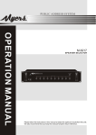
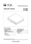
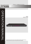
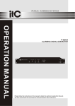
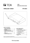
INSTRUCTION MANUAL
ANTENNA DISTRIBUTOR
WD-4800
Please follow the instructions in this manual to obtain the optimum results from this unit.
We also recommend that you keep this manual handy for future reference.
1. SAFETY PRECAUTIONS
• Be sure to read the instructions in this section carefully before use.
• Make sure to observe the instructions in this manual as the conventions of safety symbols and messages regarded as
very important precautions are included.
• We also recommend you keep this instruction manual handy for future reference.
WARNING
Indicates a potentially hazardous situation which, if mishandled, could result
in death or serious personal injury.
• Do not expose the unit to rain or an environment where it may be splashed by water or other liquids, as doing so may
result in fire or electric shock.
• Use the unit only with the voltage specified on the unit. Using a voltage higher than that which is specified may result in
fire or electric shock.
• Do not cut, kink, otherwise damage nor modify the power supply cord. In addition, avoid using the power cord in close
proximity to heaters, and never place heavy objects -- including the unit itself -- on the power cord, as doing so may
result in fire or electric shock.
• Avoid installing or mounting the unit in unstable locations, such as on a rickety table or a slanted surface. Doing so may
result in the unit falling down and causing personal injury and/or property damage.
• To prevent lightning strikes, install the unit at least five meters away from a lightning rod, and yet within the protective
range (angle of 45°) of the lightning conductor. Lightning strikes may cause a fire, electric shock or personal injury.
• Since the unit is designed for in-door use, do not install it outdoors. If installed outdoors, the aging of parts causes the
unit to fall off, resulting in personal injury. Also, when it gets wet with rain, there is a danger of electric shock.
• Should the following irregularity be found during use, immediately switch off the power, disconnect the power supply plug
from the AC outlet and contact your nearest TOA dealer. Make no further attempt to operate the unit in this condition as
this may cause fire or electric shock.
·
·
·
·
If you detect smoke or a strange smell coming from the unit.
If water or any metallic object gets into the unit
If the unit falls, or the unit case breaks
If the power supply cord is damaged (exposure of the core, disconnection, etc.)
• To prevent a fire or electric shock, never open nor remove the unit case to modify the unit. Refer all servicing to your
nearest TOA dealer.
• Do not place cups, bowls, or other containers of liquid or metallic objects on top of the unit. If they accidentally spill into
the unit, this may cause a fire or electric shock.
• Do not touch a plug or antenna during thunder and lightning, as this may result in electric shock.
CAUTION
Indicates a potentially hazardous situation which, if mishandled, could result
in moderate or minor personal injury, and/or property damage.
• Never plug in nor remove the power supply plug with wet hands, as doing so may cause electric shock.
• When unplugging the power supply cord, be sure to grasp the power supply plug; never pull on the cord itself. Operating
the unit with a damaged power supply cord may cause a fire or electric shock.
• When moving the unit, be sure to remove its power supply cord from the wall outlet. Moving the unit with the power cord
connected to the outlet may cause damage to the power cord, resulting in fire or electric shock. When removing the
power cord, be sure to hold its plug to pull.
• Avoid installing the unit in humid or dusty locations, in locations exposed to the direct sunlight, near the heaters, or in
locations generating sooty smoke or steam as doing otherwise may result in fire or electric shock.
Indicates a potentially hazardous situation which, if mishandled, could result
in moderate or minor personal injury, and/or property damage.
CAUTION
• Do not place heavy objects on the unit as this may cause it to fall or break which may result in personal injury and/or
property damage. In addition, the object itself may fall off and cause injury and/or damage.
• If dust accumulates on the power supply plug or in the wall AC outlet, a fire may result. Clean it periodically. In addition,
insert the plug in the wall outlet securely.
• Switch off the power, and unplug the power supply plug from the AC outlet for safety purposes when cleaning or leaving
the unit unused for 10 days or more. A fire or electric shock may result.
2. GENERAL DESCRIPTION
The TOA Wireless Antenna Distributor WD-4800 is designed to be used in conjunction with a VHF/UHF band system for
sound reinforcement applications. It comes with two channels, in which two input signals are mixed and distributed to four
outputs. The WD-4800 also has four DC power distribution outputs.
3. HANDLING PRECAUTIONS
• When installing, keep the unit, receiving antennas, and antenna cables as far away as possible from fluorescent lamps,
digital equipment, personal computers, and other equipment which generate high frequency noise.
• Avoid installing the receiving antennas in close proximity to metal objects, such as iron frames and lockers. Keep the
antennas at least 30 cm away from the wall surface.
• Keep two antennas at least 3 m away from each other to obtain the optimum diversity effect, although this distance
differs depending on the construction and size of the room where they are installed.
• When cleaning the case, use a dry cloth. Never use benzine, thinner or other volatile liquids.
4. NOMENCLATURE AND FUNCTIONS
2
[Front]
POWER
ON
OFF
ANTENNA INPUT (75 Ω)
ANTENNA DISTRIBUTOR WD-4800
3
4
1
1. Power switch
Press this switch to switch on the power. Press this
switch again to switch off the power.
3. Front antenna input A
75 Ω, BNC. Delivers 9 V DC/25 mA for supplying
power to an external antenna.
2. Power lamp
Lights when the power is switched on.
4. Front antenna input B
75 Ω, BNC. Delivers 9 V DC/25 mA for supplying
power to an external antenna.
[Rear]
120V/230V
50/60Hz 25W
TUNER POWER SUPPLY
13V 250 mA
VOLTAGE SELECT
120V
ANT OUTPUT B (75 Ω)
ANT INPUT B
(75 Ω)
ANT OUTPUT A (75 Ω)
ANT INPUT A
(75 Ω)
230V
ANTENNA DISTRIBUTOR WD-4800
5
6
7
5. AC inlet
6. AC voltage selector
Selects the desired voltage.
7. DC power distribution output
Distributes the DC power.
8. Rear antenna input B
75 Ω, BNC. Delivers 9 V DC/25 mA for supplying power
to an external antenna.
8
9
ENGINEERED IN JAPAN
10
ASSEMBLED IN TAIWAN
11
9. Antenna distribution output B
75 Ω, BNC.
10. Antenna distribution output A
75 Ω, BNC.
11. Rear antenna input A
75 Ω, BNC. Delivers 9 V DC/25 mA for supplying power
to an external antenna.
5. CONNECTION
• Up to four WT-4800 tuners can be connected to the WD-4800 using one or two receiving antennas.
• The length of the antenna cables between the WD-4800 and the WT-4800 must not exceed 1 m.
YW-4500
YW-4500
YW-4500
YW-4500
Connect to the front antenna inputs
WD-4800
120V/230V
50/60Hz 25W
TUNER POWER SUPPLY
VOLTAGE SELECT
120V
ANT OUTPUT B (75 Ω)
ANT INPUT B
(75 Ω)
13V 250 mA
ANT OUTPUT A (75 Ω)
ANT INPUT A
(75 Ω)
230V
ANTENNA DISTRIBUTOR WD-4800
WT-4800
ANT B
DC IN
REMOTE
ENGINEERED IN JAPAN
OUTPUT (600Ω)
(BALANCED)
(UNBALANCED)
MIX IN (10kΩ)
ANT A
(UNBALANCED)
–20dBV
LEVEL
IN
OUT
OUT
12–18V
WT-4800
ANT B
250DmA
DC IN
REMOTE
LINE
–20dBV
OUTPUT (600Ω)
IN
HOT
COLD
MIC
–50dBV
(BALANCED)
(UNBALANCED)
MIX IN (10kΩ)
ANT A
(UNBALANCED)
–20dBV
LEVEL
IN
OUT
OUT
12–18V
WT-4800
ANT B
250DmA
DC IN
REMOTE
LINE
–20dBV
OUTPUT (600Ω)
IN
HOT
COLD
MIC
–50dBV
(BALANCED)
(UNBALANCED)
MIX IN (10kΩ)
ANT A
(UNBALANCED)
–20dBV
LEVEL
IN
OUT
OUT
12–18V
WT-4800
ANT B
250DmA
DC IN
REMOTE
LINE
–20dBV
OUTPUT (600Ω)
(UNBALANCED)
IN
HOT
COLD
MIC
–50dBV
(BALANCED)
MIX IN (10kΩ)
ANT A
(UNBALANCED)
–20dBV
LEVEL
IN
OUT
OUT
12–18V
250DmA
LINE
–20dBV
MIC
–50dBV
HOT
COLD
IN
ASSEMBLED IN TAIWAN
6. OPERATION
Step 1. Turn on the power of both the WD-4800 and connected tuners (the power lamp lights).
Step 2. Set the wireless microphone switch to the ON position.
7. RACK MOUNTING
Use an optional MB-15B bracket when mounting the unit in an equipment rack.
Step 1. Remove rubber feet on the unit's bottom surface.
Step 2. Using the screws supplied with the MB-15B, mount the MB-15B to the unit's sides.
Mounting bracket MB-15B (optional)
3 x 14 screw (supplied with MB-15B)
Step 3. Using other screws also supplied with the MB-15B, mount the unit in the rack.
Rack
M5 fiber washer (supplied with MB-15B)
M5 x 12 screw (supplied with MB-15B)
8. SPECIFICATIONS
Power Source
Power Consumption
Frequency Range
Distribution Channel
Antenna Input
Antenna Output
DC Power Supply
Indicator
Operating Temperature
Finish
Dimensions
Weight
AC mains (120 V/230 V selectable)
25 W
VHF/UHF
2 channels
2 inputs (front x 1, rear x 1), 75 Ω, BNC (phantom powering of 9 V DC/25 mA for antenna)
4 outputs, 75 Ω, BNC
4 outputs (Each output: 13 V DC/250 mA)
Power lamp
–10 to +50°C
Front panel: Al coating, black
Case:
Pre-coated steel plate, black
420 (w) x 44 (h) x 305.5 (d) mm
3.55 kg
Note: The design and specifications are subject to change without notice for improvement.
• Accessories
DC cable ............................................................ 4
• Optional Product
Rack mounting bracket MB-15B
Printed in Taiwan
133-07-186-5B