1
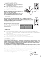
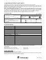
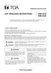
INSTRUCTION MANUAL
UHF WIRELESS MICROPHONE
WM-5270
Thank you for purchasing TOA's UHF Wireless Microphone.
Please carefully follow the instructions in this manual to ensure long, trouble-free use of your equipment.
1. SAFETY PRECAUTIONS
• Be sure to read the instructions in this section carefully before use.
• Make sure to observe the instructions in this manual as the conventions of safety symbols and messages
regarded as very important precautions are included.
• We also recommend you keep this instruction manual handy for future reference.
WARNING
Indicates a potentially hazardous situation which, if mishandled, could
result in death or serious personal injury.
• To prevent the electromagnetic wave from badly influencing medical equipment, make sure to switch off the
unit's power when placing it in close proximity to the medical equipment.
CAUTION
Indicates a potentially hazardous situation which, if mishandled, could
result in moderate or minor personal injury, and/or property damage.
• When the unit is not in use for 10 days or more, be sure to take the battery out of the unit because battery
leakage may cause personal injury or contamination of environment.
• Make sure to observe the following handling precautions so that a fire or personal injury does not result from
leakage or explosion of the battery.
· Do not short, disassemble, heat nor put the battery into a fire.
· Do not solder a battery directly.
· Be sure to use the specified type of battery.
· Note correct polarity (positive and negative orientation) when inserting a battery in the unit.
· Avoid locations exposed to the direct sunlight, high temperature and high humidity when storing batteries.
• Attention should be drawn to the environmental aspects of battery disposal.
CAUTION TO USER: Changes or modifications not expressly approved by the party responsible for
compliance could void the user's authority to operate the equipment.
2. GENERAL DESCRIPTION
The TOA's WM-5270 Wireless Microphone employs a dynamic microphone with high input handing capacity,
and is suitable for vocal use.
3. FEATURES
• One frequency can be selected from 64 frequencies (16 channels x 4 banks) of 692 – 865 MHz.
• An optimized PLL-synthesizer minimizes the oscillation frequency drift resulting from the ambient
temperature or voltage fluctuation.
• The maximum input sound pressure can be set in the range of 130 dB SPL to 142 dB SPL by a PAD switch,
permitting adaptation to wide range of input sound pressure.
• Power/Battery lamps indicate battery consumption to prevent the unit from malfunctioning when the battery
level remarkably decreases.
• Operates on a single AA battery.
• Employs a built-in antenna.
• The state of battery consumption can be displayed on the tuner's indicator when the unit is used in
conjunction with the optional WT-5800, WT-5805 or WT-5810 Wireless Tuner.
4. HANDLING PRECAUTIONS
• Do not expose the unit to rain or an environment where it may be splashed by water or other liquids, as
doing so may result in unit failure.
• Never open nor remove the unit case to modify the unit. Refer all servicing to your nearest TOA dealer.
• Take care not to drop the unit onto the floor nor bump it against a hard object as the unit could fail.
• Do not place the unit in locations of high temperature (ex. in a car parked in summer) or high humidity as the
unit could fail.
• Do not use the unit in locations where it is exposed to seawater.
• To clean, use a dry cloth. When the unit gets very dirty, wipe lightly with a cloth damped in a dilute neutral
cleanser, then wipe with a dry cloth. Never use benzine, thinner, or chemically-treated cleaning towel.
• Avoid using a mobile telephone near the wireless microphone in use. Noise could be picked up.
• When using two or more wireless microphones, keep them at least 50 cm away from each other to avoid
malfunctions or noise.
• Keep the wireless microphone at least 3 m away from the receiving antenna. Using the microphone in close
proximity to the antenna could result in malfunctions or noise.
5. NOMENCLATURE
Pad switch
This switch is used for microphone sensitivity adjustment.
The sensitivity can be decreased by 0, –6, or –12 dB.
H
0
-6
-12
PAD
New Emphasis circuit ON/OFF switch
L
H
0
-6
-12
PAD
I /O
L
I /O
BANK
CHANNEL
4
67
5
4
3
21
3
2
1
8 9
A
B
C
D
E
0F
BANK
4
3
2
1
CHANNEL
8
67 9A
5
B
C
4
D
3
21
E
0F
H: ON*
L: OFF
* Enables further noise suppression
(Valid only for WT-5800 series Wireless Tuners)
Channel selector switch
Power/Battery lamps
• A green LED lights as long as the battery capacity is sufficient. When the battery
capacity becomes low, the green LED starts to dim, while the red LED to light.
• The microphone does not transmit the signal if the channel selector switch is set to
the idle channel. In this case, the red LED and green LED flash alternately.
POWER
Power ON/OFF switch
Pressing this switch for more than one second turns the power on or off.
6. REPLACING THE BATTERY
Step 1. Hold down the power switch for one second or more to turn off the
power.
Step 2. Hold the microphone body and rotate the microphone grip
counterclockwise to remove it.
Step 3. Insert an AA battery according to (+) and (–) indications on the
battery compartment.
Step 4. Replace the microphone grip by sliding and rotating it clockwise.
Battery replacement
• A brand-new AA alkaline battery will continuously operate the unit for
about 10 hours.
• When the battery capacity becomes low, the green LED of the
Power/Battery lamps starts to dim, while the red LED to light. When only
the red LED lights, replace the battery with a new one. In this condition,
the unit transmits the remaining battery capacity information to the tuner,
causing the tuner's BATT indicator to light.
2
3
2
[Bottom]
POWER
Red LED
Green LED
1 Power ON/OFF switch
7. CHANNEL NUMBER SETTING
H
0
-6
-12
PAD
Step 1. Switch off the power. Rotate the microphone grip
counterclockwise to remove it.
Step 2. Using the screwdriver housed in the microphone
body, set the Channel selector switch pointer to
the desired channel number.
Step 3. Replace the microphone grip.
BANK
CHANNEL
4
67
5
4
3
21
3
2
1
Note
Make sure that the wireless microphone is identical to the
wireless tuner in the channel number.
Should the microphone's setting differ from that of the
tuner, the tuner does not receive the microphone signal.
8 9
A
B
C
D
E
0F
Channel selector
switch
8. PAD SWITCH
Pad switch
The input sensitivity can be decreased by 0 dB, –6 dB or –12 dB with the PAD switch.
Select the appropriate level so that the output sound is not distorted when the volume
control knob of the tuner is set at the 2 o'clock position.
If a loud voice distorts the output sound, decrease the sensitivity by shifting the PAD switch
to the –6 dB or –12 dB position.
H
0
-6
-12
PAD
BANK
CHANNEL
4
67
5
4
3
21
3
2
PAD switch
0 dB
–6 dB
–12 dB
Maximum input level
130 dB SPL
136 dB SPL
142 dB SPL
L
I /O
Note: The PAD switch is factory-preset to 0 dB.
The table at right shows the relationship
between the PAD switch positions and the
maximum input levels.
L
I /O
1
8 9
A
B
C
D
E
0F
9. OPERATION
Step 1. Confirm that the wireless microphone and the wireless tuner are identical in the channel number.
If not identical, turn off the power ON/OFF switch, then set the channel number to the same channel
number as the tuner.
Step 2. Hold down the power switch for one second or more to turn on the power.
Then, confirm the green LED of the Power/Battery lamps will light.
Step 3. Hold down the power switch for one second or more to turn off the power after use.
10. OPERATIONAL HINTS
• The microphone's service distance is 3 – 120 m. When the microphone user moves in a facility, signal
dropouts (momentary losses of signal reception) may be encountered. These dropouts are caused by the
building's architectural designs or materials which block the travel of or reflect the radio signal. If this occurs,
the user needs to change locations for better signal reception.
• The proper operation of your wireless system may be interfered with by other system operating on the same
frequency. In such cases, change the operating frequency of your system. (As to dealing with the
interference, refer to the operating instructions of the wireless tuner.)
• Should you have any questions regarding the use or availability of TOA wireless products, please contact
your local TOA dealer.
• If the output sound is distorted at the large volume level, use the microphone by shifting the PAD (input
sensitivity reduction) switch to the –6 dB or –12 dB position to decrease the sensitivity.
• Attach the supplied rolling stopper as needed, preventing the microphone
from rolling and dropping onto the floor.
WM-5270
Rolling stopper
(supplied)
3
11. NEW EMPHASIS CIRCUIT ON/OFF SWITCH
The WM-5270 incorporates an improved new Emphasis circuit that further suppresses noise.
The Emphasis circuit can be switched to the new circuit (pre-compressor Emphasis) by setting the New
Emphasis circuit ON/OFF switch to ON (H position), and to the conventional circuit (post-compressor
Emphasis) by setting the switch to OFF (L position).
When using the WM-5270 with the switch set to ON, also reset the WT-5800 series tuner to a new circuit by
means of the optional RW-4800 ROM Writer. So, further noise suppressed and clearer sound can be assured.
The WM-5270 is compatible with the WT-4800 series turners when shipped from the factory (New Emphasis
circuit ON/OFF switch: OFF). Once the switch is set to ON, however, no more compatibility is ensured.
The table below shows the compatibility between the Wireless Microphones and Tuners.
[Compatibility table]
: Compatible
WM-5270
Wireless Microphones
New Emphasis circuit
ON/OFF switch:
ON (H)
Wireless Tuners
WT-5800
series
H
L
New Emphasis circuit
ON/OFF switch:
OFF (L)
H
L
Pre-compressor (New Emphasis circuit)
Post-compressor
(Conventional Emphasis circuit)
WT-4800 series
12. SPECIFICATIONS
Microphone Element
Modulation
Frequency Range
Selectable Channel
RF Carrier Power
Tone Frequency
Oscillator
Maximum Input Level
Dynamic microphone unit, cardioid pattern
Frequency modulation
692 – 865 MHz, UHF
64 frequencies (the number of channels may differ from country to country.)
Less than 50 mW
32.768 kHz
PLL synthesized
142 dB SPL
Maximum Deviation
Audio Frequency Response
Dynamic Range (AF Circuit)
Battery
Battery Life
Indicator
Antenna
Operating Temperature
Finish
Dimensions
Weight
±40 kHz
80 – 15,000 Hz
More than 95 dB (with WT-5800)
LR6 (AA)
More than 10 hours (alkaline)
Power/Battery lamps
Built-in type
–10 to +50°C
Dark gray
ø48 x 244 mm
340 g (with battery)
Note: The design and specifications are subject to change without notice for improvement.
• Accessories
Microphone holder (with stand adapter) ............... 1
Screwdriver for setting (housed in the body) ........ 1
Storage case ........................................................ 1
Rolling stopper ..................................................... 1
License requirement
Operation is subject to the following two conditions:
(1) This device may not cause harmful interference, and (2) this device must accept any interference received,
including interference that may cause undesired operation.
133-07-241-50