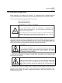
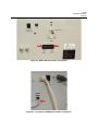
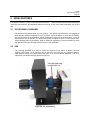
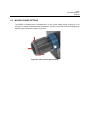
1
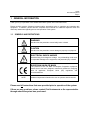
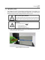
APEX2 s ® Oriel Illumination Systems User's Manual Family of Brands – ILX Lightwave® • New Focus™ • Ophir® • Corion • Richardson Gratings™ • Spectra-Physics® MAPEX2, Rev B 10/15/2014 Apex2 Illumination Systems Page 2 TABLE OF CONTENTS 1 2 3 4 5 6 7 8 9 10 11 GENERAL INFORMATION .................................................................................................................. 5 1.1 SYMBOLS AND DEFINITIONS ............................................................................................. 5 1.2 GENERAL WARNINGS ......................................................................................................... 6 1.3 ELECTRICAL HAZARDS ....................................................................................................... 6 1.4 FIRE HAZARDS ..................................................................................................................... 7 1.5 LAMP HANDLING .................................................................................................................. 7 INTRODUCTION .................................................................................................................................. 8 SYSTEM SETUP ................................................................................................................................ 13 3.1 ITEMS INCLUDED WITH SYSTEM ..................................................................................... 13 3.2 UNPACKING ........................................................................................................................ 13 3.3 CHOOSING A LOCATION ................................................................................................... 13 3.4 LAMP INSTALLATION ......................................................................................................... 14 3.5 ELECTRICAL CONNECTION .............................................................................................. 21 3.6 LAMP INTENSITY ADJUSTMENT (APEX2-QTH ONLY) .................................................... 23 CONTROLLING THE APEX2 FILTER WHEEL ................................................................................. 24 4.1 MANUAL CONTROL ............................................................................................................ 25 4.2 DIRECT APEX2 COMPUTER CONTROL ........................................................................... 25 4.3 MONOCHROMATOR UTILITY SOFTWARE CONTROL .................................................... 26 4.4 MONOCHROMATOR COMMAND SET .............................................................................. 28 4.5 MONOCHROMATOR HAND CONTROLLER...................................................................... 28 4.6 TRACQ BASIC CONTROL .................................................................................................. 29 APEX2 FEATURES ............................................................................................................................ 30 5.1 FILTER WHEEL OVERVIEW ............................................................................................... 30 5.2 IRIS....................................................................................................................................... 30 5.3 SHUTTER ............................................................................................................................ 31 5.4 ADJUSTABLE COLLIMATING LENS .................................................................................. 32 5.5 MATING FLANGE OPTIONS ............................................................................................... 33 FILTER INSTALLATION .................................................................................................................... 34 UNIVERSAL FILTER WHEEL UTILITY SOFTWARE ........................................................................ 36 7.1 SYSTEM REQUIREMENTS ................................................................................................ 36 7.2 SOFTWARE INSTALLATION PROCEDURE ...................................................................... 37 7.3 USING THE FILTER WHEEL UTILITY SOFTWARE .......................................................... 41 7.4 COMMAND SET .................................................................................................................. 43 ACCESSORIES.................................................................................................................................. 44 8.1 MONOCHROMATOR MOUNTING KITS ............................................................................. 44 8.2 FIBER FOCUSING ASSEMBLIES ....................................................................................... 44 8.3 FOCUSING LENS ASSEMBLIES ........................................................................................ 45 8.4 BEAM TURNERS ................................................................................................................. 45 8.5 UV SAFETY ACCESSORIES .............................................................................................. 46 MAINTENANCE ................................................................................................................................. 47 9.1 LAMP REPLACEMENT........................................................................................................ 47 9.2 CLEANING ........................................................................................................................... 47 9.3 LAMP CARE AND HANDLING ............................................................................................ 47 9.4 FUSE REPLACEMENT ........................................................................................................ 47 SPECIFICATIONS.............................................................................................................................. 48 10.1 APEX2 ILLUMINATOR......................................................................................................... 48 10.2 UNIVERSAL FILTER WHEEL UTILITY SOFTWARE .......................................................... 49 EU DECLARATION OF CONFORMITY............................................................................................. 50 Apex2 Illumination Systems Page 3 12 WARRANTY AND SERVICE ............................................................................................................. 51 12.1 CONTACTING ORIEL INSTRUMENTS............................................................................... 51 12.2 REQUEST FOR ASSISTANCE / SERVICE......................................................................... 52 12.3 REPAIR SERVICE ............................................................................................................... 52 12.4 NON-WARRANTY REPAIR ................................................................................................. 52 12.5 WARRANTY REPAIR .......................................................................................................... 53 12.6 LOANER / DEMO MATERIAL .............................................................................................. 54 LIST OF FIGURES Figure 1: Basic System Block Diagram ........................................................................................................ 9 Figure 2: Dimension Diagram .................................................................................................................... 10 Figure 3: Xenon Lamp Spectra .................................................................................................................. 11 Figure 4: QTH Lamp Spectra ..................................................................................................................... 12 Figure 5: Remove Top Cover Screws ........................................................................................................ 14 Figure 6: Remove Housing Cover .............................................................................................................. 15 Figure 7: Remove Lamp Cable Holder ...................................................................................................... 15 Figure 8: Remove Lamp Cable Holder ...................................................................................................... 16 Figure 9: Unfasten Power Supply Cable .................................................................................................... 16 Figure 10: Insert Lamp ............................................................................................................................... 17 Figure 11: Lamp Ellipse Positioning Groove .............................................................................................. 17 Figure 12: Secure Lamp............................................................................................................................. 18 Figure 13: Connect Lamp Wiring ............................................................................................................... 18 Figure 14: Re-attach Lamp Cable Holder .................................................................................................. 19 Figure 15: Completed Lamp Installation (Xenon and QTH)....................................................................... 19 Figure 16: Safety Interlock ......................................................................................................................... 20 Figure 17: Cover Re-installed .................................................................................................................... 20 Figure 18: APEX2 Power Connection ........................................................................................................ 22 Figure 19: Lamp Intensity Adjustment Settings ......................................................................................... 23 Figure 20: Filter Wheel Connectors ........................................................................................................... 24 Figure 21: Manual Control Configuration ................................................................................................... 25 Figure 22: Direct Computer Control Configuration..................................................................................... 25 Figure 23: Monochromator Control Configuration ..................................................................................... 26 Figure 24: MS257 Monochromator Connections ....................................................................................... 27 Figure 25: Cornerstone USB Monochromator Connections ...................................................................... 27 Figure 26: APEX2 Configured with Hand Controller .................................................................................. 28 Figure 27: Filter Selection Table in TracQ Basic ....................................................................................... 29 Figure 28: Iris Control Ring ........................................................................................................................ 30 Figure 29: Shutter Knob ............................................................................................................................. 31 Figure 30: Collimating Lens Adjustment .................................................................................................... 32 Figure 31: Do Not Adjust Relay Lens ......................................................................................................... 32 Figure 32: Oriel 1.5-Inch Series Flange ..................................................................................................... 33 Figure 33: Filter Wheel Cover Screws ....................................................................................................... 34 Figure 34: Filter Wrench Removing Retaining Ring .................................................................................. 35 Figure 35: Installed Filters .......................................................................................................................... 35 Figure 36: Setup Application ...................................................................................................................... 37 Figure 37: Destination Directory Selection................................................................................................. 37 Figure 38: Accept License Agreements ..................................................................................................... 38 Figure 39: Start Installation ........................................................................................................................ 38 Figure 40: Finish Installation ...................................................................................................................... 39 Figure 41: Restart Computer...................................................................................................................... 39 Apex2 Illumination Systems Page 4 Figure 42: Start Menu and Desktop Changes............................................................................................ 40 Figure 43: Connect to Filter Wheel ............................................................................................................ 41 Figure 44: Device ID Query........................................................................................................................ 41 Figure 45: Select Filter ............................................................................................................................... 42 Figure 46: Query Filter Position ................................................................................................................. 42 Figure 47: Fiber Focusing Assembly ......................................................................................................... 44 Figure 48: Model 6195 Optic Holder ........................................................................................................... 45 Figure 49: Beam Turning Reflector Holder ................................................................................................. 45 Figure 50: Protective Gloves ....................................................................................................................... 46 Figure 51: 49125 Safety Spectacles ........................................................................................................... 46 Figure 52: Fuse Compartment .................................................................................................................... 47 Apex2 Illumination Systems Page 5 1 GENERAL INFORMATION Thank you for your purchase of this APEX2 illumination system from Oriel Instruments. Please carefully read the following important safety precautions prior to unpacking and operating this equipment. In addition, please read the complete User’s Manual for additional important notes and cautionary statements regarding the use and operation of the system. 1.1 SYMBOLS AND DEFINITIONS WARNING Situation has the potential to cause bodily harm or death. CAUTION Situation has the potential to cause damage to property or equipment. ELECTRICAL SHOCK HAZARD Hazard arising from dangerous voltage. Any mishandling could result in irreparable damage to the equipment, and personal injury or death. EUROPEAN UNION CE MARK The presence of the CE Mark on Newport Corporation equipment means that it has been designed, tested and certified as complying with all applicable European Union (CE) regulations and recommendations. NOTE: Additional important information the user or operator should consider. Please read all instructions that were provided prior to operation of the system. If there are any questions, please contact Oriel Instruments or the representative through whom the system was purchased. Apex2 Illumination Systems Page 6 1.2 1.3 GENERAL WARNINGS • Read all warnings and operating instructions for this system prior to setup and use. • Do not use this equipment in or near water. • To prevent damage to the equipment, read the instructions in the equipment manual for proper input voltage. • This equipment is grounded through the grounding conductor of the power cord. • Route the power cord and other cables so they are not likely to be damaged. • Disconnect power before cleaning the equipment. • Do not use liquid or aerosol cleaners; use only a dry lint-free cloth. • Lock out all electrical power sources before servicing the equipment. • To avoid explosion, do not operate this equipment in an explosive atmosphere. • Qualified service personnel should perform safety checks after any service. • If this equipment is used in a manner not specified in this manual, the protection provided by this equipment may be impaired. • To prevent damage to equipment when replacing fuses, locate and correct the problem that caused the fuse to blow before re-applying power. • Do not block ventilation openings. • Do not position this product in such a manner that would make it difficult to disconnect the power cord. • Use only the specified replacement lamp. • This product should only be powered as described in the manual. • Do not remove the cover for normal usage. ELECTRICAL HAZARDS Make all connections to or from the power supply with the power off. Do not use the power supply without its cover in place. Lethal voltages are present inside. Apex2 Illumination Systems Page 7 1.4 FIRE HAZARDS Lamps are extremely hot during operation, and for several minutes after being shut off. Keep flammable objects away from the lamp and lamp housing. Newport Research (fan-cooled) Housings are equipped with a condenser lens. The re-focused output of this lens can cause ignition of flammable targets including but not limited to walls, certain chemicals. To avoid fire hazard, use only the specified fuses with the correct type number, voltage and current ratings as referenced in the appropriate locations in the service instructions or on the equipment. Only qualified service personnel should replace fuses. 1.5 LAMP HANDLING Read all information and warnings provided with lamp. The Xenon arc lamps used in one of the APEX2 models is filled with rare gas at high pressure, so there is a danger of lamp explosion due to mechanical failure. This is particularly true when the lamp is operating since the internal pressure can reach tens of atmospheres. Thermal strains can cause the lamp to explode under certain conditions. Never touch any lamp or the reflector’s inner surface with bare fingers or other contaminates. Skin oil or other substances can burn into the lamp envelope during operation and negatively affect the lamp’s performance and lifetime. Always wear appropriate gloves and impact-resistant goggles when handling any lamp. Avoid any mechanical strain during handling. Do not operate the lamp without all housing panels in place. Lamps become very hot after only a few minutes of operation (up to 150°C) and remain quite hot for at least 10 to 15 minutes after being turned off. Apex2 Illumination Systems Page 8 2 INTRODUCTION The APEX2 series of illumination systems are designed as compact, economical and fully integrated solutions for a wide variety of applications. The APEX2 is a turnkey solution producing a collimated 1.3 inch (33 mm) diameter output beam. Just install the lamp, connect the power cord and switch on the power – then the system is ready for use. The systems are available with either a Xenon or Quartz Tungsten Halogen (QTH) lamp. Lamp replacement is easy – no alignment is needed. The lamp operates with a built-in power supply, so no current or power adjustments are required. The APEX2 is designed with an ellipsoidal reflector, capturing additional light to increase optical throughput. The APEX2 is designed to be quick and easy to set up. Mounting feet help with handling and leveling the illuminator. The mounting feet are removable, so the illuminator may be permanently mounted to an optical table if desired. The APEX2 comes preassembled on a plate with mounting holes for securing the illuminator to an inch or metric optical table / breadboard. The light source is coupled to a filter wheel, where up to six neutral density or ordering sorting filters may be installed. A large, easy to read digital display indicates which filter is in the light path. Filters are ordered separately, as their specifications are application-dependent. The filters may be selected using a variety of methods, including manual control and software. For those who wish to create their own programs, low level commands may be sent to the system via its USB connection to the computer. The APEX2 includes a manually operated shutter. It is important that the lamp is warmed up and stabilized when using the system. When the lamp is not needed, it can remain on (and therefore warmed up) by closing off the light path. NOTE: Always allow the lamp to warm up for at least 30 minutes prior to beginning work. The output flange of the APEX2 is compatible with the 1.5-inch Oriel flanging system. The collimated output may be coupled to a wide variety of items such as a beam turner, focusing optics, fiber optic cable adapter or detector. Compatible instruments: • • • • • Cornerstone 130 Monochromator Cornerstone 260 Monochromator MS260i Spectrograph MS257 Monochromator MS257 Spectrograph NOTE: In this user’s manual, the term “monochromator” is used throughout the text. operated with both monochromators and spectrographs. The APEX2 may be Apex2 Illumination Systems Page 9 Filter Iris Selection Ring Button Light Source / Power Supply * Relay Optics are set and locked during assembly. Do not adjust under normal circumstances. Shutter Knob Relay Optics* Filter Wheel Collimating Optics Figure 1: Basic System Block Diagram Apex2 Illumination Systems Page 10 NOTE: All dimensions are in inches. Figure 2: Dimension Diagram Apex2 Illumination Systems Page 11 Figure 3: Xenon Lamp Spectra Apex2 Illumination Systems Page 12 Figure 4: QTH Lamp Spectra Apex2 Illumination Systems Page 13 3 SYSTEM SETUP 3.1 ITEMS INCLUDED WITH SYSTEM Oriel Instruments provides a pre-aligned light source and filter wheel installed on a mounting plate. In addition, the system includes: 3.2 Lamp APEX2 utility software Filter wrench 1/16 hex wrench Power Cord User’s manual UNPACKING Remove all items from the shipping containers and verify each item is accounted for. The system is carefully packaged to minimize the possibility of damage during shipment. Inspect the shipping boxes for external signs of damage or mishandling. Inspect the contents for damage. If any item is missing or damaged, immediately contact Oriel Instruments or the Newport representative from whom the system was purchased. It is suggested to save the packaging material and shipping container, in case the equipment needs to be relocated at a future date. WARNING Do not attempt to operate this equipment if there is evidence of shipping damage or there is suspicion that the equipment will not operate correctly. Damaged equipment may present hazards. 3.3 CHOOSING A LOCATION Choose an installation location where the power requirements can be met for the system. Be sure power is not applied to the system until the setup has been completed. The environment should be that of a typical laboratory atmosphere, without excessive humidity and contaminants in the air. Do not allow the ventilation holes on the illuminator or its computer to be blocked. Air should be able to circulate freely around the system. Carry the instrument by its base plate. When the system is placed in its final location, check to ensure that none of the pre-assembled items have become loose during transportation and handling. Apex2 Illumination Systems Page 14 3.4 LAMP INSTALLATION Before plugging in the power cord and powering up the APEX2, the lamp must be installed. The lamp is shipped in its own box to prevent damage during transportation. It is suggested to keep this box, as it can be utilized if moving or transporting the APEX2 in the future. Never move the APEX2 while the lamp is installed. Damage to the lamp or system may result. ELECTRICAL SHOCK HAZARD Do not open the APEX2 cover and attempt to work inside without first turning the instrument off and disconnecting the power cord from the AC mains. Failure to follow this warning can result in severe injury or death. WARNING When installing the lamp, it is required to: • • • Wear eye protection. Wear powder-free gloves. Make sure the power is turned off. 1. Using a philips head screwdriver, remove the (4) screws holding the top cover of the housing and set aside. Refer to Figure 6. Figure 5: Remove Top Cover Screws Apex2 Illumination Systems Page 15 2. Remove the top cover and set aside as shown in Figure 6. Figure 6: Remove Housing Cover 3. Loosen and remove the knurled thumb screw shown in Figure 7. Remove the lamp cable holder plate and set aside with the thumb screw. Figure 7: Remove Lamp Cable Holder Apex2 Illumination Systems Page 16 4. Squeeze lamp holder wires towards each other and then pull towards the back of the power supply. Refer to Figure 8. Figure 8: Remove Lamp Cable Holder 4. The power supply cable shown in Figure 9 is secured for transportation. Unfasten it and let it hang to the side for now. The Xenon lamp cable is shown. The appearance of the QTH cable differs slightly. Figure 9: Unfasten Power Supply Cable Apex2 Illumination Systems Page 17 5. Insert the lamp as shown in Figure 10. The outer edge of the elliptical reflector must fit into the groove shown in Figure 11. CAUTION Always wear powder-free gloves or finger cots when handling the lamp. Handle the lamp from the outside of the reflector. Making contact with the lamp or reflector may cause permanent damage. Figure 10: Insert Lamp Figure 11: Lamp Ellipse Positioning Groove Apex2 Illumination Systems Page 18 6. Clamp the lamp in place by returning the lamp holder wires to their original location per Figure 12. Figure 12: Secure Lamp 7. Connect the lamp wiring to the power supply cable. The Xenon lamp connectors are designed so that they cannot be connected backwards, so there is no need to be concerned with lamp polarity. See Figure 13. Figure 13: Connect Lamp Wiring Apex2 Illumination Systems Page 19 8. Re-attach the lamp cable holder which was set aside earlier by tightening the thumb screw as shown in Figure 14. The completed lamp installation is shown in Figure 15, with Xenon on the left and QTH on the right. Figure 14: Re-attach Lamp Cable Holder Figure 15: Completed Lamp Installation (Xenon and QTH) Apex2 Illumination Systems Page 20 9. Re-install the cover, taking care that the cover’s safety interlock lines up with its slot as shown in Figure 16. Figure 16: Safety Interlock 10. Using a philips head screwdriver, re-install the (4) screws to secure the top cover of the housing. Do not leave out any screws. Figure 17: Cover Re-installed Apex2 Illumination Systems Page 21 3.5 ELECTRICAL CONNECTION Before powering up the system for the first time, it is suggested to have a qualified electrician verify the wall socket to be used with the APEX2 meets the requirements for operation as noted. The line voltage requirements for the APEX2 are as follows: 100 to 120 VAC, 50-60 Hz 200 to 240 VAC, 50-60 Hz ELECTRICAL SHOCK HAZARDS To avoid electric shock, connect the instrument to a properly earthgrounded, 3-prong receptacle only. Failure to observe this precaution can result in severe injury or death. Never attempt to open the lamp power supply or monochromator power adapter. These items do not contain any user serviceable parts. Failure to follow this warning can result in severe injury or death. The APEX2 systems conforms to CE standards for both safety and EMC. During normal use, this equipment will not pose any electrical hazards to the user. Read all warnings before installing or operating this system. Never open the APEX2 cover and attempt to work inside without first turning the instrument off and disconnecting the power cord from the AC mains. CAUTION Do not turn on the APEX2 until all connections have been made to the monochromator, computer, hand controller and/or external 5 VDC source. Refer to Section 4 for information on various methods and required connections to control the APEX2. If there are any questions or concerns, contact Oriel Instruments or the regional sales representative for Newport. WARNING When the power switch is turned on, the lamp will begin emitting light immediately. Do not turn on the APEX2 until the output flange is directed in such a way that people, animals and equipment will not be harmed by the light. A dedicated power line or line isolation may be required in certain locations, as the electronics contained in the instrument are sensitive to static electricity and radiated electromagnetic fields. Operation of the system near intense pulsed sources (lasers, Xenon flash lamps, etc.) may compromise performance. Apex2 Illumination Systems Page 22 Before making any electrical connections, verify the power switches are in the OFF position for the APEX2 and monochromator, if being used. Connect the power cord to the back of the APEX2 before to plugging it into an AC electrical outlet. NOTE: Power switch is in the OFF position. Figure 18: APEX2 Power Connection NOTE: Always allow the lamp to warm up for at least 30 minutes prior to beginning work. Apex2 Illumination Systems Page 23 3.6 LAMP INTENSITY ADJUSTMENT (APEX2-QTH ONLY) The model APEX2-QTH includes a feature allowing the lamp intensity to be controlled by an external DC voltage source. External control is enabled by moving the toggle switch on the back panel to the UP position. When the toggle switch is in the DOWN position, the lamp will operate at its full power rating of 100 watts. The BNC female connector on the back of the APEX2-QTH is used to connect a DC voltage source. The input voltage range is 0 to 5 VDC. 0 VDC corresponds to the lamp being off; 5 VDC allows the lamp to run at its maximum power of 100 watts. NOTE: In the event that the lamp isn’t operating and no external voltage source is being applied, check the toggle switch position and ensure it is in the DOWN position. BNC connector for external DC voltage source EXT FULL External control enabled Full power (100 watts) Figure 19: Lamp Intensity Adjustment Settings Apex2 Illumination Systems Page 24 4 CONTROLLING THE APEX2 FILTER WHEEL The APEX2 integrates a light source, filter wheel and power supply. Power is supplied to both the lamp and the filter wheel. A large, easy to read digital display indicates which filter is active, i.e. which filter is in the light path. The readout is positioned on the filter wheel assembly to face towards the rear of the light source, so that it may be monitored from a safe and convenient viewing angle. The filters may be selected using the following: • • • • • • Manual pushbutton control Direct APEX2 computer control Oriel Monochromator Utility program Monochromator command set Monochromator Hand Controller Oriel TracQ Basic radiometry software For those who wish to create their own programs, low level commands may be sent to the system via its USB connection to the computer. Filter installation is covered in Section 0. Manual filter selection pushbutton Ribbon cable connectors for Oriel Cornerstone and MS257 monochromators USB cable connector for use with Universal Filter Wheel Utility software Figure 20: Filter Wheel Connectors Apex2 Illumination Systems Page 25 4.1 MANUAL CONTROL Pressing the pushbutton located on the back of the filter wheel, as shown in Figure 21, advances the filter by one position. Figure 21: Manual Control Configuration 4.2 DIRECT APEX2 COMPUTER CONTROL The APEX2 filter wheel comes with its own utility program and command set. To utilize these control options, connect the filter wheel directly to a computer using a USB cable. Refer to Figure 22 for wiring connection information. Section 7 discusses the utility program and command set in detail. Figure 22: Direct Computer Control Configuration Apex2 Illumination Systems Page 26 4.3 MONOCHROMATOR UTILITY SOFTWARE CONTROL Oriel’s Cornerstone and MS257 series monochromators include a utility program used to query and command the instruments. When the filter wheel is connected to the monochromator, the monochromator’s utility program may be used to control both instruments. Refer to the monochromator user’s manual for more information. Ensure the power switches switch for the APEX2 and monochromator are in the off position (marked as O). Then connect the power adapter and all other cables to the monochromator, as shown in Figure 25. The monochromator is connected to the APEX2 filter wheel using a ribbon cable provided with the APEX2 monochromator adapter kits. Adapter kits are listed in Section 8.1. Connect the ribbon cable to the filter wheel using whichever connector matches the pin configuration of the cable. Connect the other end of the power cord to the AC mains only after the lamp has been installed and all other connections made. Once the APEX2 and monochromator are powered on, the monochromator allows the user to select which filter is placed in the optical path. Figure 23: Monochromator Control Configuration Apex2 Illumination Systems Page 27 Figure 24: MS257 Monochromator Connections Figure 25: Cornerstone USB Monochromator Connections Apex2 Illumination Systems Page 28 4.4 MONOCHROMATOR COMMAND SET For those who want to incorporate monochromator as well as APEX2 filter wheel control into their own custom software, both instruments may be controlled by the command set used by the monochromator. Set up the monochromator and APEX2 as noted in Section 4.3 and Figure 23. Refer to the monochromator’s user manual for information on the command set. 4.5 MONOCHROMATOR HAND CONTROLLER For those who do not wish to use a computer to control the Cornerstone Series and MS257 Series monochromators, Oriel offers hand controllers which plug directly into the monochromators. When the APEX2 is connected to the monochromator via a filter wheel ribbon cable, the hand controller can be used to select a filter. Refer to the monochromator’s user manual for more information. Control the Monochromator and Filter Wheel with an Oriel hand controller Ribbon cable Hand Controller Connector Filter Wheel Connector APEX2 MONOCHROMATOR To AC power outlet Note that exact location of monochromator connectors varies based on model. To AC power outlet Figure 26: APEX2 Configured with Hand Controller Apex2 Illumination Systems Page 29 4.6 TRACQ BASIC CONTROL In order to ensure that the light exiting the monochromator is truly monochromatic, it is necessary to incorporate optical filters into the design. The physics of diffraction gratings is such that higher order wavelengths need to be blocked. The filters installed into the APEX2 need to be chosen to block unwanted wavelengths. By setting the filter parameters in the TracQ Basic software, the monochromator automatically selects the appropriate filter for any desired wavelength. Refer to the TracQ Basic manual for more information. Figure 27 shows the filter setup screen for a Cornerstone monochromator. The MS257 setup screen is similar, but uses five filters and up to two filter wheels simultaneously. Figure 27: Filter Selection Table in TracQ Basic NOTE: The parameters entered in Figure 27 are an example. The actual filter changeover parameters depend on the monochromator configuration and filters being used. Apex2 Illumination Systems Page 30 5 APEX2 FEATURES The APEX2 provides a number of accessories and features. This makes the APEX2 product family both convenient and compact. All integrated features are built-in, so the unit is easy to transport, set up and use. 5.1 FILTER WHEEL OVERVIEW The motorized filter wheel holds up to six (6) filters. The MS257 monochromator was designed to work with filter wheels containing up to five (5) filters. When the MS257 is used with the APEX2, the first five filters will be selectable. When used alone or with other monochromators, all six (6) filter positions may be utilized. The active filter position change at a rate of 1.7 seconds per filter. When applying power to the APEX2, Refer to Section 4 regarding the various methods by which the filter wheel may be controlled and Section 0 for filter installation. 5.2 IRIS The manually operated iris is used to control the intensity of the Xenon or Quartz Tungsten Halogen (QTH) lamp. At its minimum, the iris acts as a 0.25 inch (6.4 mm) diameter aperture. Light intensity ranges from 100% when fully open to 2% at its minimum diameter. The iris is adjusted by turning the black ring shown in Figure 28. Turn the black ring to adjust the iris Figure 28: Iris Control Ring Apex2 Illumination Systems Page 31 5.3 SHUTTER The integrated shutter is a very convenient feature which may be used to close off the light path while the lamp is warming up. Frequently restarting the lamp may shorten the lamp’s life and requires warm-up time. If the lamp is not needed for a short amount of time, the shutter can simply be closed. Turning the knob clockwise opens the shutter. Rotating the knob counterclockwise closes the shutter. Turn the knob to open and close the shutter Figure 29: Shutter Knob Apex2 Illumination Systems Page 32 5.4 ADJUSTABLE COLLIMATING LENS The collimating lens may be adjusted to optimize light coupling. Loosen the silver thumb screw shown in Figure 30. Turn the blue knob near the output flange to change the lens position. Be sure to tighten the locking screw when finished. Note: under normal circumstances, this is the only lens which should be adjusted. Do not make any changes to the relay lens position, as its position was optimized before shipment. Figure 30: Collimating Lens Adjustment DO NOT ADJUST! Figure 31: Do Not Adjust Relay Lens Apex2 Illumination Systems Page 33 5.5 MATING FLANGE OPTIONS The APEX2 is designed with a standard Oriel 1.5-inch series mating flange, allowing it to be coupled to a variety of instruments and accessories. Items are connected to the mating flange by tightening three set screws, shown in Figure 32. Figure 32: Oriel 1.5-Inch Series Flange Apex2 Illumination Systems Page 34 6 FILTER INSTALLATION WARNING When the light source is in use, the filter wheel and all other items in the optical path may become hot. Ensure items are cool before handing them. Ensure the shutter is closed and the lamp is off whenever working in the filter wheel compartment. Remove the front plate of the filter wheel assembly by unscrewing eight (8) flat head screws using a philips screwdriver. Refer to Figure 33. Set all items aside, ensuring that no foreign matter can contaminate or damage the optics. Do not attempt to disconnect the output optics and flange from the front plate. Figure 33: Filter Wheel Cover Screws Each filter position is labeled on the wheel. Remove the filter retaining ring using the filter wrench included with the system. Insert the filter and re-install the retaining ring. Always wear gloves or finger cots when handing optics. See Figure 34 and Figure 35. For all filter positions which are not being utilized, ensure the retaining rings are snug so that they do not work themselves free and jam the filter wheel. Only then should the filter cover be re-installed. Note: Always keep track of which filters are installed at each position. It is suggested to write down this information and update it whenever the configuration is changed. This is particularly helpful in a multiuser environment. Apex2 Illumination Systems Page 35 Figure 34: Filter Wrench Removing Retaining Ring Figure 35: Installed Filters Apex2 Illumination Systems Page 36 7 UNIVERSAL FILTER WHEEL UTILITY SOFTWARE The following procedure acquaint the first time user with the installation and use of the APEX2 utility software. Do not be concerned if your display does not exactly agree with the figures shown. The focus of this manual is to help the first time user learn how to install and use the software. It is highly recommended that the first time user read these instructions before attempting to use or install the software. To install the software, the APEX2 utility software, a compatible computer, and a APEX2 illuminator are required. Installation of APEX2 utility program will create: • • • 7.1 a folder called C:\Program Files\Newport - Oriel Instruments\Universal USB Filter Wheel (an alternative directory may be chosen during the installation process) an icon called “USB Filter Wheel Utility” in the start menu an icon for NI Max on the desktop SYSTEM REQUIREMENTS Operating System Microsoft Windows XP, Service Pack 3 Microsoft Windows 7, 32-bit and 64-bit Requires Microsoft .net Framework 4.0 Processor Speed 2 GHz minimum Random Access Memory (RAM) 1 GB minimum Peripheral Hardware CD-ROM, USB 2.0 port Hard Drive Space 800 MB minimum Apex2 Illumination Systems Page 37 7.2 SOFTWARE INSTALLATION PROCEDURE 1. Turn on the computer following the manufacturer’s instructions. Before installing the software, close all applications. Disconnect all instruments from the computer before installing this software. 2. Insert the Utility installation disk into the computer’s CD-ROM drive. The “AutoPlay” dialog box may open. Select “Open folder to view files.” If the “AutoPlay” does not start installing the software automatically, open the contents of the installation disk. 3. Double click the Setup.exe application, shown in Figure 36, application to begin the installation. Figure 36: Setup Application 4. When the “Destination Directory” screen appears, the option is available to install the software into the default location or a different location. To install software into a different location, click the “Browse” button and select another directory. There are separate directories for APEX2 and National Instruments Products, as shown in Figure 37. Click “Next” to continue. During the installation, it is normal for other dialog boxes to flash as software is added. Figure 37: Destination Directory Selection Apex2 Illumination Systems Page 38 5. Choose to accept the license agreements and click Next. Figure 38: Accept License Agreements 6. Click “Next” to start installation. Otherwise click “Back” to change the installation settings. Note: Clicking “Save File” will save a file in Rich Text File format (*rtf). The .rtf file will list the installation summary text. This file will be named “save as install.rtf”. Figure 39: Start Installation Apex2 Illumination Systems Page 39 7. During installation, a status indicator will show the overall progress. Selecting “Cancel” brings up a dialog box to verify cancellation. 8. When the installation is complete, click “Finish”. Refer to Figure 40. Figure 40: Finish Installation 9. A dialog box will appear to restart the computer, as shown in Figure 41. This software can be used only after the computer is restarted. Figure 41: Restart Computer Apex2 Illumination Systems Page 40 10. After the computer restarts, the Start menu shall contain the Filter Wheel Utility software and the National Instruments “NI Max” icon shall appear on the desktop, as shown in Figure 42. Figure 42: Start Menu and Desktop Changes Apex2 Illumination Systems Page 41 7.3 USING THE FILTER WHEEL UTILITY SOFTWARE 1. After the Filter Wheel Utility software is installed and the computer restarted, connect the APEX2 to the computer via a USB cable and turn on the illuminator. 2. Run the utility program. 3. Select the instrument, and click the “Connect” button. NOTE: If the software is unable to connect, check in the device manager to ensure that the USB driver has been installed correctly and the instrument is listed. Figure 43: Connect to Filter Wheel 4. To verify communication, click “Device ID?” Figure 44: Device ID Query Apex2 Illumination Systems Page 42 5. To select a filter, click the pulldown menu and choose the desired filter position. Figure 45: Select Filter 6. To verify which filter is currently in the light path, click “Filter #?” Figure 46: Query Filter Position 7. To disconnect from communication with the filter wheel, click “Disconnect” . Apex2 Illumination Systems Page 43 7.4 COMMAND SET To ensure latency and guaranteed delivery, all communications with the device uses the control pipeline defined by the USB communications protocol. COMMAND SYNTAX Use Line Feed <LF> as the termination character for all commands. The HEX value for <LF> is “0a” or the decimal value is 10 Example: Command: *IDN?<LF> Response: APEX2-XE, 001, 1.0<LF> where <LF> is the line feed character COMMAND LIST All commands listed below automatically assumes the line feed character is used as the termination character. *IDN? Identification query. Returns identification string ‘Oriel Instruments, APEX2 Illumination System, XXXXX, YYYYY, ZZZZZ' where XXXXX, YYYYY and ZZZZZ are the Model, Serial, and Firmware numbers of the system. Example: Command: *IDN?<LF> Response: APEX2-XE, 001, 1.0 The response indicates that this is a product of Oriel Instruments, the product name is APEX2 Illumination System, the model number is APEX2-XE, the Serial number is 001, and the firmware version is 1.0. FILT? Queries active filter position. Returns number of the current filter position or -1 for error. FILT X Sets active filter position, where X is the desired filter position from 1-6. Apex2 Illumination Systems Page 44 8 ACCESSORIES The following is a small list of the optional accessories available which may be used with the APEX2. For more information, visit Newport’s website or contact Newport’s technical sales engineers. They can help configure a full system from the extensive Oriel and Newport product selection. 8.1 MONOCHROMATOR MOUNTING KITS Oriel offers a selection of mounting kits which provide a common baseplate and interconnection hardware used to connect the APEX2 to many of Oriel’s monochromators and spectrographs. 8.2 Instrument Mounting Kit Model Cornerstone 130 Monochromator APEX2-CS1-KIT Cornerstone 260 Monochromator APEX2-CS2-KIT MS260i Spectrograph APEX2-CS2-KIT MS257 Monochromator APEX2-MS1-KIT MS257 Spectrograph APEX2-MS1-KIT FIBER FOCUSING ASSEMBLIES Fiber Focusing Assemblies efficiently collect and focus the collimated beam of light from the APEX2 onto a fiber optic cable or liquid light guide. These assemblies attach directly to the output of the APEX2. Figure 47: Fiber Focusing Assembly Apex2 Illumination Systems Page 45 8.3 FOCUSING LENS ASSEMBLIES To focus the collimated output of the APEX2 into a concentrated spot, connect the Oriel model 6195 lens holder (shown in Figure 48) to the APEX2 output flange. Choose any 1.5-inch (38.1 mm) lens from Newport’s extensive selection or order one of Oriel’s preconfigured Focusing Lens Assemblies. Figure 48: Model 6195 Optic Holder 8.4 BEAM TURNERS The light path extends horizontally out from the APEX2. To direct the beam up, down or sideways, order one of Oriel’s beam turning reflector holders. Then choose a dichroic or full reflector to install into the holder. Figure 49: Beam Turning Reflector Holder Apex2 Illumination Systems Page 46 8.5 UV SAFETY ACCESSORIES Ultraviolet (UV) light is known to cause both short-term and long-term damage to eyes and skin. The lamps used with the APEX2 do emit UV light to varying degrees. Oriel offers various accessories to protect the eyes, face and hands. Figure 50 shows protective gloves, which are available in two different sizes. Figure 51 shows the popular model 49125 UV safety glasses alongside the APEX2. Figure 50: Protective Gloves Figure 51: 49125 Safety Spectacles Apex2 Illumination Systems Page 47 9 MAINTENANCE 9.1 LAMP REPLACEMENT The average life of each lamp type is noted below. Note that the lifetime of the lamp can be affected by the manner in which it is used. Frequent ignitions, contamination of the lamp envelope and an excessively hot operating environment all will lead to reduced lamp life. To avoid system down time, consider purchasing a replacement lamp as the lamp nears the end of its useful life. Refer to the Section 3.4 of this manual for information on lamp installation. APEX2 Model Lamp Type APEX2-QTH 100 W QTH APEX2-XE 100 W Xe 9.2 Lamp Model 6338 6252 Average Lifetime 500 hours 1000 hours CLEANING Clean the exterior of the APEX2 when the illuminator is not hot from use. Use a clean, dry cloth. Ensure that the ventilation holes are not blocked with dust. Vacuum the openings, if necessary, from the outside of the unit. When not in use, cover the output port of the APEX2. Always be sure to remove the output port cover before turning on the lamp. 9.3 LAMP CARE AND HANDLING Do not allow any contaminants or fingerprints to adhere to the lamp envelope or reflector. Always wear powder-free gloves when handling lamps. Handle the lamp by holding the outside of the reflector only. If a lamp becomes contaminated, do not use it before cleaning its envelope with isopropyl alcohol. Dry completely before using. If contaminants are not removed, it may lead to reduced light output, overheating, damage to the envelope and premature failure. The lamp’s reflector is coated and should not be wiped or touched at all. Remove any particulates such as dust using a bulb blower. 9.4 FUSE REPLACEMENT The fuse compartment may be accessed from the back of the APEX 2 as shown in Figure 52. Only qualified personnel should access the fuses. Figure 52: Fuse Compartment Apex2 Illumination Systems Page 48 10 SPECIFICATIONS 10.1 APEX2 ILLUMINATOR Parameter APEX2-XE Specification Light Source 100 watt Xenon lamp with integrated reflector Lamp Model Lamp Lifetime (Average) 6252 1000 hours External Lamp Intensity Control None 0 VDC = no lamp output 5 VDC = 100 watt lamp output 9.2 ± 0.4 watts 9.4 ± 0.4 watts 4.0° ± 0.5° 5.0° ± 0.5° 33 ± 2 mm diameter 38 ± 2 mm diameter Optical Power (Iris fully open) Divergence (Half Angle) Spot Size (measured at 28.5 mm from output flange, iris fully open) Light Ripple (rms) F-Number Temporal Stability Lens Material Lens Transmittance Range Number of Filters Filter Diameter Filter Thickness Connection Flange Shutter Iris AC Input and 5x20 mm Fuses (quantity 2) < 0.2% APEX2-QTH Specification 100 watt Quartz Tungsten Halogen lamp with integrated reflector 6338 500 hours 0 to 5 VDC control signal < 0.07% F/4.0 < 1% Fused Silica 200 to 2500 nm Holds up to six (6) filters, ordered separately. Uses maximum five (5) with MS257 monochromator 1 inch [25.4 mm] 0.23 inch [6.0 mm] maximum Oriel 1.5-Inch Series Female Flange Manually Controlled Manually Controlled, 0.25 inch [6.4 mm] diameter to fully open 100 to 120 VAC, 50 to 60 Hz / 1.5 A, 250 V Time Delay Fuse 200 to 240 VAC, 50 to 60 Hz / 0.8 A, 250 V Time Delay Fuse Apex2 Illumination Systems Page 49 Parameter Operating Environment IEC Classification Storage Temperature Size Weight Optical Axis Height Safety Interlock CE Compliance RoHS Compliance Specification 5 to 40°C [41 to 104°F] , indoor use only < 80% relative humidity (non-condensing) < 3000 m [9843 ft] altitude Installation Category II, Pollution Degree 2 0 to 50°C [32 to 122°F] 19.88 x 6.57 x 8.92 inch [505 x 167 x 227 mm] 13 lb [5.9 kg] 4 inch [102 mm] Lamp shuts off when cover is removed or when internal temperature exceeds normal operating conditions Yes Yes 10.2 UNIVERSAL FILTER WHEEL UTILITY SOFTWARE Parameter Operating System Processor Speed Random Access Memory (RAM) Peripheral Hardware Hard Drive Space Specification Microsoft Windows XP, Service Pack 3 Microsoft Windows 7, 32-bit and 64-bit Requires Microsoft .net Framework 4.0 2 GHz minimum 1 GB minimum CD-ROM, USB 2.0 port 800 MB minimum Note: One USB 2.0 port is required to connect between the computer and APEX2 filter wheel. Additional USB ports may be required when controlling other instruments, such as a monochromator, lock-in amplifier, power meter, etc. Apex2 Illumination Systems Page 50 11 EU DECLARATION OF CONFORMITY We declare that the accompanying product, identified with the mark, complies with requirements of the Electromagnetic Compatibility Directive, 2014/30/EU and the Low Voltage Directive 2006/95/EC. Model Numbers: APEX2-XE, APEX2-QTH Year mark affixed: 2014 Type of Equipment: Electrical equipment for measurement, control and laboratory use in industrial locations. Manufacturer: Newport Corporation 1791 Deere Avenue Irvine, CA 92606 Standards Applied: Compliance was demonstrated to the following standards to the extent applicable: BS EN61326-1: 2013 “Electrical equipment for measurement, control and laboratory use – EMC requirements” for use in a controlled electromagnetic environment. This equipment meets the EN55011:2009+A1:2010 Class A Group 1 radiated and conducted emission limits. BS EN 61010-1:2010, “Safety requirements for electrical equipment for measurement, control and laboratory use”. Mark Carroll Sr. Director, Instruments Business Newport Corporation 1791 Deere Ave, Irvine, CA 92606 USA Apex2 Illumination Systems Page 51 12 WARRANTY AND SERVICE 12.1 CONTACTING ORIEL INSTRUMENTS Oriel Instruments belongs to Newport Corporation's family of brands. Thanks to a steadfast commitment to quality, innovation, hard work and customer care, Newport is trusted the world over as the complete source for all photonics and laser technology and equipment. Founded in 1969, Newport is a pioneering single-source solutions provider of laser and photonics components to the leaders in scientific research, life and health sciences, photovoltaics, microelectronics, industrial manufacturing and homeland security markets. Newport Corporation proudly serves customers across Canada, Europe, Asia and the United States through 9 international subsidiaries and 24 sales offices worldwide. Every year, the Newport Resource catalog is hailed as the premier sourcebook for those in need of advanced technology products and services. It is available by mail request or through Newport's website. The website is where one will find product updates, interactive demonstrations, specification charts and more. To obtain information regarding sales, technical support or factory service, United States and Canadian customers should contact Oriel Instruments directly. Oriel Instruments 150 Long Beach Boulevard Stratford, CT 06615 USA Telephone: 800-714-5393 (toll-free in United States) 203-377-8282 Fax: 203-378-2457 Sales: [email protected] Technical assistance: [email protected] Repair Service: [email protected] Customers outside of the United States must contact their regional representative for all sales, technical support and service inquiries. A list of worldwide representatives can be found on Oriel's website: http://www.newport.com/oriel. Apex2 Illumination Systems Page 52 12.2 REQUEST FOR ASSISTANCE / SERVICE Please have the following information available when requesting assistance or service: Contact information for the owner of the product. Instrument model number (located on the product label). Product serial number and date of manufacture (located on the product label). Description of the problem. To help Oriel's Technical Support Representatives diagnose the problem, please note the following: Is the system used for manufacturing or research and development? What was the state of the system right before the problem? Had this problem occurred before? If so, when and how frequently? Can the system continue to operate with this problem, or is it non-operational? Were there any differences in the application or environment before the problem occurred? 12.3 REPAIR SERVICE This section contains information regarding factory service for this product. The user should not attempt any maintenance or service of the system beyond the procedures outlined in this manual. This product contains no user serviceable parts other than what is noted in this manual. Any problem that cannot be resolved should be referred to Oriel Instruments. If the instrument needs to be returned for service, a Return Material Authorization (RMA) number must be obtained prior to shipment to Oriel Instruments. This RMA number must appear on both the shipping container and the package documents. Return the product to Oriel Instruments, freight prepaid, clearly marked with the RMA number and it either will be repaired or replaced it at Oriel's discretion. Oriel is not responsible for damage occurring in transit. The Owner of the product bears all risk of loss or damage to the returned Products until delivery at Oriel's facility. Oriel is not responsible for product damage once it has left the facility after repair or replacement has been completed. Oriel is not obligated to accept products returned without an RMA number. Any return shipment received by Oriel without an RMA number may be reshipped by Newport, freight collect, to the Owner of the product. 12.4 NON-WARRANTY REPAIR For Products returned for repair that are not covered under warranty, Newport's standard repair charges shall be applicable in addition to all shipping expenses. Unless otherwise stated in Newport's repair quote, any such out-of-warranty repairs are warranted for ninety (90) days from date of shipment of the repaired Product. Oriel will charge an evaluation fee to examine the product and determine the most appropriate course of action. Payment information must be obtained prior to having an RMA number assigned. Customers may use a valid credit card, and those who have an existing account with Newport Corporation may use a purchase order. Apex2 Illumination Systems Page 53 When the evaluation had been completed, the owner of the product will be contacted and notified of the final cost to repair or replace the item. If the decision is made to not proceed with the repair, only the evaluation fee will be billed. If authorization to perform the repair or provide a replacement is obtained, the evaluation fee will be applied to the final cost. A revised purchase order must be submitted for the final cost. If paying by credit card, written authorization must be provided that will allow the full repair cost to be charged to the card. 12.5 WARRANTY REPAIR If there are any defects in material or workmanship or a failure to meet specifications, notify Oriel Instruments promptly, prior to the expiration of the warranty. Except as otherwise expressly stated in Oriel's quote or in the current operating manual or other written guarantee for any of the Products, Oriel warrants that, for the period of time set forth below with respect to each Product or component type (the "Warranty Period"), the Products sold hereunder will be free from defects in material and workmanship, and will conform to the applicable specifications, under normal use and service when correctly installed and maintained. Oriel shall repair or replace, at Oriel's sole option, any defective or nonconforming Product or part thereof which is returned at Buyer's expense to Oriel facility, provided, that Buyer notifies Oriel in writing promptly after discovery of the defect or nonconformity and within the Warranty Period. Products may only be returned by Buyer when accompanied by a return material authorization number ("RMA number") issued by Oriel, with freight prepaid by Buyer. Oriel shall not be responsible for any damage occurring in transit or obligated to accept Products returned for warranty repair without an RMA number. Buyer bears all risk of loss or damage to the Products until delivery at Oriel's facility. Oriel shall pay for shipment back to Buyer for Products repaired under warranty. WARRANTY PERIOD All Products (except consumables such as lamps, filters, etc.) described here are warranted for a period of twelve (12) months from the date of shipment or 3000 hours of operation, whichever comes first. Lamps, gratings, optical filters and other consumables / spare parts (whether sold as separate Products or constituting components of other Products) are warranted for a period of ninety (90) days from the date of shipment. WARRANTY EXCLUSIONS The above warranty does not apply to Products which are (a) repaired, modified or altered by any party other than Oriel; (b) used in conjunction with equipment not provided or authorized by Oriel; (c) subjected to unusual physical, thermal, or electrical stress, improper installation, misuse, abuse, accident or negligence in use, storage, transportation or handling, alteration, or tampering, or (d) considered a consumable item or an item requiring repair or replacement due to normal wear and tear. Apex2 Illumination Systems Page 54 DISCLAIMER OF WARRANTIES; EXCLUSIVE REMEDY THE FOREGOING WARRANTY IS EXCLUSIVE AND IN LIEU OF ALL OTHER WARRANTIES. EXCEPT AS EXPRESSLY PROVIDED HEREIN, ORIEL MAKES NO WARRANTIES, EITHER EXPRESS OR IMPLIED, EITHER IN FACT OR BY OPERATION OF LAW, STATUTORY OR OTHERWISE, REGARDING THE PRODUCTS, SOFTWARE OR SERVICES. NEWPORT EXPRESSLY DISCLAIMS ANY IMPLIED WARRANTIES OF MERCHANTABILITY OR FITNESS FOR A PARTICULAR PURPOSE FOR THE PRODUCTS, SOFTWARE OR SERVICES. THE OBLIGATIONS OF ORIEL SET FORTH IN THIS SECTION SHALL BE ORIEL'S SOLE LIABILITY, AND BUYER'S SOLE REMEDY, FOR BREACH OF THE FOREGOING WARRANTY. Representations and warranties made by any person including distributors, dealers and representatives of Oriel / Newport Corporation which are inconsistent or in conflict with the terms of this warranty shall not be binding on Oriel unless reduced to writing and approved by an expressly an authorized officer of Newport. 12.6 LOANER / DEMO MATERIAL Persons receiving goods for demonstrations or temporary use or in any manner in which title is not transferred from Newport shall assume full responsibility for any and all damage while in their care, custody and control. If damage occurs, unrelated to the proper and warranted use and performance of the goods, recipient of the goods accepts full responsibility for restoring the goods to their original condition upon delivery, and for assuming all costs and charges. Confidentiality & Proprietary Rights Reservation of Title: The Newport programs and all materials furnished or produced in connection with them ("Related Materials") contain trade secrets of Newport and are for use only in the manner expressly permitted. Newport claims and reserves all rights and benefits afforded under law in the Programs provided by Newport Corporation. Newport shall retain full ownership of Intellectual Property Rights in and to all development, process, align or assembly technologies developed and other derivative work that may be developed by Newport. Customer shall not challenge, or cause any third party to challenge the rights of Newport. Preservation of Secrecy and Confidentiality and Restrictions to Access: Customer shall protect the Newport Programs and Related Materials as trade secrets of Newport, and shall devote its best efforts to ensure that all its personnel protect the Newport Programs as trade secrets of Newport Corporation. Customer shall not at any time disclose Newport's trade secrets to any other person, firm, organization, or employee that does not need (consistent with Customer's right of use hereunder) to obtain access to the Newport Programs and Related Materials. These restrictions shall not apply to information (1) generally known to the public or obtainable from public sources; (2) readily apparent from the keyboard operations, visual display, or output reports of the Programs; 3) previously in the possession of Customer or subsequently developed or acquired without reliance on the Newport Programs; or (4) approved by Newport for release without restriction. First printing 2014 © 2014 by Newport Corporation, Irvine, CA. All rights reserved. No part of this manual may be reproduced or copied without the prior written approval of Newport Corporation. This manual has been provided for information only and product specifications are subject to change without notice. Any change will be reflected in future printings. Newport Corporation 1791 Deere Avenue Irvine, CA, 92606 USA