1
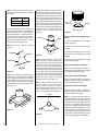
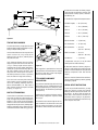
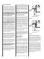
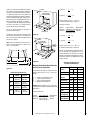
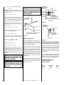
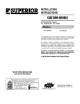
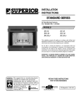
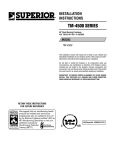
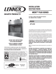
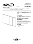
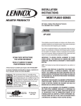
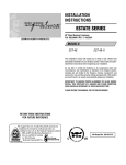
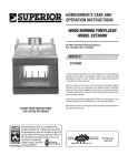
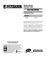
INSTALLATION
INSTRUCTIONS
CUSTOM SERIES
36" Wood Burning Fireplaces
P/N 700,023M REV. C 06/2005
MODELS
CST-38
CPF-38
This installation manual will enable you to obtain a safe, efficient and
dependable installation of your fireplace system. Please read and understand these instructions before beginning your installation.
Do not alter or modify the fireplace or its components under any
circumstances. Any modification or alteration of the fireplace system,
including but not limited to the fireplace, chimney components and
accessories, may void the warranty, listings and approvals of this system
and could result in an unsafe and potentially dangerous installation.
IMPORTANT! TO ASSURE PROPER ALIGNMENT OF GLASS DOORS:
INSTALL THIS FIREPLACE IN A SQUARE AND PLUMB CONDITION,
USING SHIMS AS NECESSARY AT SIDES AND/OR BOTTOM.
RETAIN THESE INSTRUCTIONS
FOR FUTURE REFERENCE
OTL Report No. 116-F-20-4
NOTE: DIAGRAMS & ILLUSTRATIONS NOT TO SCALE.
1
TABLE OF CONTENTS
Safety Rules .................................... page 2
Tools and Building Supplies ............ page 2
Precautions ..................................... page 3
Introduction ..................................... page 3
Clearances/Height Requirements ..... page 3
Chimney System ............................. page 4
Assembly Outline ............................. page 4
Location of Fireplace ....................... page 4
Assembly Steps ............................... page 5
Preinstallation Notes ........................ page 5
Clearances ....................................... page 5
Installing the Fireplace ..................... page 5
Fireplace Specifications .................. page 7
Framing Specifications .................... page 8
Framing Wall Variations .................. page 9
Installing the Chimney System ........ page 10
Ten Foot Rule Summary .................. page 13
3. These fireplaces must be installed with
Security Chimneys FTF8 (8" inside diameter)
Chimney System only. These systems are intended for use in any application where a
traditional masonry type fireplace would apply. The chimney system must always vent to
the outside of the building.
4. To ensure a safe fireplace system and to
prevent the build-up of soot and creosote,
inspect and clean the fireplace and chimney
prior to use and periodically during the heating
season.
5. Use solid fuel only. DO NOT use artificial
wax based logs, chemical chimney cleaners or
flame colorants in your fireplace.
Multiple Terminations ...................... page 13
Chimney Component Calculations ... page 13
6. DO NOT use charcoal or coal under any
circumstances.
Special Offset Instructions ............... page 13
Vertical Elevation Chart ................... page 14
7. NEVER use gasoline, gasoline-type lantern
fuel, kerosene, charcoal lighter fluid, or similar
liquids to start or “freshen up” a fire in this
fireplace. Keep any flammable liquids a safe
distance from the fireplace.
Offset Elevation Chart ..................... page 15
Offset Calculations ........................... page 16
Installing Offsets .............................. page 16
30° Offset through Floor/Ceiling ...... page 17
Glass Doors ..................................... page 17
Optional Equipment Considerations . page 17
Combustion Air Kits ........................ page 17
Gas Line Connection ........................ page 18
Cold Climate Insulation .................... page 18
Fireplace Finishes ............................ page 18
Mantels and Trim ............................. page 18
Hearth Extensions/Wall Shields ....... page 18
Finish Requirements ........................ page 20
Accessories And Components ......... page 20
IMPORTANT: PLEASE READ AND
UNDERSTAND THESE RULES TO
FOLLOW FOR SAFETY.
1. Before starting your fireplace installation,
read these installation instructions carefully to
be sure you understand them completely and in
entirety. Failure to follow them could cause a
fireplace malfunction resulting in serious injury
and/or property damage.
2
2. Always check your local building codes. The
installation must comply with all local, regional, state and national codes and regulations.
8. NEVER leave children unattended when
there is a fire burning in the fireplace.
9. Always keep flue damper open when heat is
present in the fireplace.
10. Before servicing, allow the fireplace to
cool. Always shut off any electricity or gas to
the fireplace while working on it. This will
prevent any possible electrical shock or burns.
11. This fireplace is not intended to heat an
entire home or be used as a primary heat
source. It is designed to ensure homeowner
comfort by providing supplemental heat to the
room.
12. Always ensure an that adequate supply of
replacement combustion air from the outside
of the house is accessible to the fire to support
normal combustion. Fireplaces consume large
volumes of air during the normal combustion
process. In the event the home is tightly sealed
with modern energy efficient features, the optional combustion air kit may not provide all
the air required to support combustion.
NOTE: DIAGRAMS & ILLUSTRATIONS NOT TO SCALE.
The manufacturer is not responsible for any
smoking or related problems that may result
from the lack of adequate combustion air. It is
the responsibility of the builder/contractor to
ensure that adequate combustion air has been
provided for the fireplace.
13. DO NOT use a fireplace insert or any other
products not specified herein by the manufacturer
for use with this fireplace. All gas log sets must be
operated with the damper clamped open.
WARNING: THIS FIREPLACE HAS NOT
BEEN TESTED WITH AN UNVENTED GAS
LOG SET. TO REDUCE RISK OF FIRE OR
INJURY, DO NOT INSTALL AN UNVENTED
GAS LOG SET INTO THIS FIREPLACE.
14. "Smoke free” operation is not warranteed
nor are we responsible for inadequate system
draft caused by mechanical systems, general
construction conditions, inadequate chimney
heights, adverse wind conditions and/or unusual environmental factors or conditions beyond our control.
15. Never, under any circumstances, install a
fireplace, chimney component or any accessories, that has visible or suspected physical
damage as a result of handling or transportation. These items should be inspected by your
distributor or qualified factory representative
to ensure safe condition. When in doubt, consult your distributor.
16. For additional safety considerations and complete operating instructions, refer to the Care and
Operation Manual provided with the fireplace.
TOOLS AND BUILDING SUPPLIES
NORMALLY REQUIRED
Tools should Include:
Phillips screwdriver
Hammer
Saw and/or sabersaw
Level
Measuring tape
Plumb line
Electric drill and bits
Pliers
Square
Building supplies:
Framing materials
Wall finishing materials
Caulking materials (noncombustible)
Fireplace surround and hearth
extension materials (noncombustible)
PRECAUTIONS
Note: These fireplace systems are not difficult
to install. However, in the interest of safety, it is
recommended that the installer be a qualified or
certified “tradesman” familiar with commonly
accepted fireplace installation and safety techniques as well as prevailing local codes.
The most important areas of concern dealing
with the installation of factory-built fireplaces are
clearances to combustible materials, proper assembly of component parts, height of the chimney system, the proper use of accessories supplied by the manufacturer and the techniques
employed in using finishing materials applied to
the wall surrounding the fireplace, hearth extensions and wall shields. Each of these topics will
be covered in thorough detail throughout this
manual. Please give each your special attention
as you progress with your installation.
INTRODUCTION
General Information
The CST-38 and CPF-38 Series are radiantheat, two-sided and three-sided fireplaces with
required glass doors, that must be ordered
separately. A steel grate is included with the
CST-38 and CPF-38 to properly position the
fire. An outside combustion air kit is available
as optional equipment.
Note: Illustrations shown reflect “typical” installations with nominal dimensions and are for
design and framing reference only. Actual installations may vary due to individual design preferences. However, always maintain minimum clearances to combustible materials and do not violate any specific installation requirements.
The CST and CPF systems consists of four
“subsystems”:
These fireplaces have been tested and listed by
Omni Test Labs (Report No. 116-F-20-4) to
U.L. standard 127. These units are intended for
installation in residential homes and other buildings of conventional construction including
commercial, not in mobile homes.
CLEARANCES AND HEIGHT
REQUIREMENTS
These fireplace systems are designed for installation in accordance with the National Fire
Protection Standard for chimneys, fireplaces
and solid fuel burning appliances; NFPA 211
and in accordance with codes such as the BOCA
Basic/National Codes, the Standard Mechanical Code and the Uniform Building Codes.
WARNING: FAILURE TO USE MANUFACTURE PROVIDED PARTS, VARIATIONS IN
TECHNIQUES AND CONSTRUCTION MATERIALS OR PRACTICES OTHER THAN
THOSE DESCRIBED IN THIS MANUAL
MAY CREATE A FIRE HAZARD AND VOID
THE LIMITED WARRANTY.
TYPICAL INSTALLATION
Chimney and
Termination
1.
2.
3.
4.
The Fireplace and Door Assemblies
The Chimney and Termination
The Optional Combustion Air Kit
The Chimney Air Kit (Canada Only)
The fireplace may be placed on or near normal
construction materials*. The combustion air
kit, firestop spacer and roof flashing (not chase
flashings) may be placed directly on or against
normal construction materials.* The chimney
and fireplace outer wrapper require a minimum 2" and 1" air space to combustibles
respectively. A combustible mantle may be
installed 12" above the opening of the fireplace
as per NFPA 211, Section 7-2.3.3.
The CPF-38 fireplace opening must be kept a
minimum of 8" (203 mm) from an unprotected
combustible side wall. The CST-38 fireplace
opening must be kept a minimum of 8"
(203 mm) from a protected combustible side
wall. A perpendicular side wall can not be
closer that 7" (178 mm) for both the CPF-38
and CST-38 fireplaces. If there is a continuous
perpendicular side wall closer than 18" from
the CST-38 fireplace opening, it must be protected with a 40" x 40" x ¹⁄₂" (1016 mm x
1016 mm x 13 mm) wall shield constructed of
millboard or a durable noncombustible material with an equal or greater insulating value
than k=.84 BTU IN/FT2 HR °F (refer to page 18).
As with all chimney installations, avoid overhead obstructions such as trees, power lines,
etc. Additionally chimney terminations must
meet certain clearance to roof requirements
detailed in the paragraph titled Ten-Foot Rule
Summary.
The fireplace and chimney system must be
enclosed when installed in or passing through
a living area where combustibles or people
may come in contact with it. This is important
to prevent possible personal injury or fire
hazard.
Model CPF-38
Model CST-38
*Construction Materials:
• framing materials
• particle board
• millboard
• plywood
• paneling
• flooring
• dry wall
• etc.
Figure 1
NOTE: DIAGRAMS & ILLUSTRATIONS NOT TO SCALE.
3
For questions, please call your distributor or
the manufacturer. Special restrictions apply to
the front and facing of the fireplace and nearby
walls (See pages 18, 19 and 20 ).
CHIMNEY SYSTEM
These fireplaces are designed and code listed
for use with Security Chimneys FTF8 chimney
System only. Always use Security Chimneys
FTF8 chimney components with these fireplaces. Do not modify or alter these components as this may cause a potential serious
hazard and void the Warranty.
Insulate Joists
Same As Ceiling
Note: Local codes may not require firestopping
at the ceiling levels for outside chase installations. However, it is recommended for safety
and the reduction of heat loss.
The total height of your CST and CPF fireplace
systems from the surface the fireplace rests
on to the chimney top must not exceed 80'
(24.4m) and must also meet minimum system
height chart.
CTDT
Termination
Note: NonCombustible
Chase
Flashing
Must Be
Used To
Cover
Chase
Opening
Minimum System Height
Optional
Insulation
In Outside
Walls Of
Chase
8'
Level
Check the operation of the damper. The damper
is controlled through the use of a control lever
located within the firebox opening at the top
center just behind the firebox lintel (Figure 3 ).
The control lever snaps into place at the extreme range of motion, up and back in the
closed position. When pulled forward and
down, the damper is open.
Damper
Closed
Damper
Open
Lintel
Model CST-38
and CPF-38
Security's
FTF8
Vertical Installation
15' 0" (4.6 m)
One Offset
16' 0" (4.9 m)
Two Offsets
25' 0" (7.6 m)
Figure 3
LOCATION OF FIREPLACE
Carefully select the proper location for heat
circulation, aesthetics, chimney obstructions
and clearance to side wall(s). With proper preplanning, a slight adjustment of a few inches
can save considerable time and expense later
during construction and assembly.
Chase Enclosure
Solid
Continuous
Surface
4
Check your inventory list to be sure you have all
the necessary parts supplied in good usable
condition. Check also for any concealed damage.
Chimney Height
Firestop
Figure 2
WARNING: DO NOT PACK OR FILL REQUIRED AIR SPACES WITH INSULATION
OR OTHER MATERIAL. NO MATERIAL IS
ALLOWED IN THESE AREAS.
ASSEMBLY OUTLINE
Before You Start
Note: Do not insulate the chase cavity with
blown or fill type insulation materials.
Draft Stops
Insulation
(Thermal Barrier)
WARNING: IF INSULATION IS USED, THE
FIREPLACE MUST NOT BE PLACED DIRECTLY AGAINST IT. INSULATION OR
VAPOR BARRIERS, IF USED, MUST FIRST
BE COVERED WITH GYPSUM BOARD,
PLYWOOD, PARTICLE BOARD OR OTHER
MATERIAL TO ASSURE INSULATION AND
VAPOR BARRIERS REMAIN IN PLACE.
Outside
Base
A chase is a vertical box-like structure constructed to surround the fireplace and chimney.
Refer to Figure 2 for a typical chase configuration. A chase should be constructed and insulated just like any outside wall. In a cold climate,
we recommend the base of the chase should
also be insulated between the solid continuous
floor beneath the fireplace and the chase bottom. Chase insulation in a cold climate installation is not required for safety.
NOTE: DIAGRAMS & ILLUSTRATIONS NOT TO SCALE.
Figure 4
Carefully consider the position of the fireplace
opening with respect to the location of adjacent or nearby stairwells, bath or kitchen exhaust fans and/or return air registers for forced
air furnaces/air conditioners that could cause
a smoking fireplace condition if the house is
tightly insulated.
This system is intended to be installed in residential homes and buildings of conventional
construction, not in mobile homes.
When locating the fireplace, consideration must
be given to combustibles and final finishing.
For an example of this, see Figure 5 and
confine the final location of combustible finish
materials to the "Safe Zone".
DO NOT permanently place furniture or other
items such as decorative pillows within 60" of
the fireplace front face.
Black Portion Of Frame
Not To Be Covered With
Combustible Materials
Wall
Covering
12”
6. Install both “All-GlassTM” door assemblies.
CLEARANCES
7. Complete finish wall material, surround and
hearth extension to your individual taste.
Minimum clearance to combustibles for the
appliance is as follows: sides and back - 1" (25
mm), floor - 0" (0 mm), adjacent wall - 12" (305
mm), ceiling - 37 ¹⁄₂" (953 mm).
Study the three dimensional illustration (Figure 1 ) to get a general idea of each element of
your fireplace system.
PRE-INSTALLATION NOTES
The fireplace may be installed directly on a
combustible floor or raised on a platform of an
appropriate height. Do not place fireplace on
carpeting, vinyl or other soft floor coverings. It
may, however, be placed on flat wood, plywood, particle board or other hard surfaces.
Be sure fireplace rests on a solid continuous
floor or platform with appropriate framing for
support and so that no cold air can enter the
room from under the fireplace.
The fireplace may be positioned and then the
framing built around it, or the framing may be
constructed and the fireplace positioned into
the opening.
INSTALLING THE FIREPLACE
Step 1. Slide the fireplace into prepared framing or position fireplace in its final position and
frame later.
The fireplace may not be recessed into a combustible floor. Maintain the floor to hearth clearance established by the fireplace lower front
face.
Step 2. Insert the provided metal safety strips,
beneath the fireplace as illustrated (Figures 6, 7
and 8 ). The safety strips should overlap ¹⁄₂" for
continual coverage of the floor.
Note: Safety strips are not required when fireplace rests on a noncombustible surface.
Usually, no special floor support is needed for
the fireplace, however, to be certain:
45°
1”
Door
Opening
12”
Safe
Zone
Figure 5
ASSEMBLY STEPS
Note: The following steps represent the normal
sequence of installation. Each installation is
unique, however, and might require a different
sequence.
1. Position firebox prior to framing or into
prepared framing.
2. Install the chimney air kit (Canada only)
3. Install the chimney system.
1. Estimate the total weight of the fireplace
system including chimney and surround materials such as brick, stone, etc., to be installed. Shipping weights for the fireplace may
be found on page 18.
2. Measure the square footage of the floor
space to be occupied by the system, surrounds
and hearth extensions.
Hearth
Extension
Metal Safety
Strips
Floor
Floor
Figure 6
3. Note the floor construction, i.e. 2 x 6’s, 2 x 8’s
or 2 x 10’s, single or double joists, type and
thickness of floor boards.
4. Use this information and consult your local
building code to determine if you need additional support.
Hearth
Extension
CAUTION: DO NOT BLOCK THE HEAT-CIRCULATING AIR INLET AND OUTLET PORTS ON
CIRCULATING MODELS. DOING SO MAY RESULT IN A POTENTIAL FIRE HAZARD.
4. Install optional outside combustion air kit.
5. Plumb gas line if a decorative gas appliance
will be used. (Gas connections should only be
performed by an experienced, licensed/certified tradesman).
Hearth
Extension
If you plan to raise the fireplace and hearth
extension, build the platform assembly then
position fireplace and hearth extension on top.
Secure the platform to the floor to prevent
possible shifting.
NOTE: DIAGRAMS & ILLUSTRATIONS NOT TO SCALE.
Hearth
Extension
Metal Safety
Strips
Platform
Floor
Figure 7
Note: Install the hearth extension only as illustrated.
5
If the appliance is to be elevated above floor
level, a solid continuous platform must be
constructed.
Platform
The header may rest on the top metal spacers,
but must not be notched to fit around them.
Consult all local codes.
*
Metal
Safety Strips
No Combustible
Materials in
Shaded Areas
*
2" Min.
(51 mm)
*
* 2" Min. (51 mm)
Figure 8
Figure 10
*
*
Figure 13
Metal
Safety Strips
*
*
* 2" Min.
* 2" Min.
Figure 9
The safety strips should extend in front and
sides of the fireplace opening 2" (51 mm) . In
the event a wooden support is used to elevate
the fireplace above the floor, a “Z” type safety
strip should be fabricated and used to protect
the front surface of the wood support as well
as the floor beneath the hearth extension (see
Figures 8, 9, 10, and 11 ). The safety strips
should be tacked down to prevent possible
movement.
(51 mm)
*
Special “Z”
Metal Safety Strips
Figure 11
IMPORTANT: UNDER NO CIRCUMSTANCES
CAN THE FIREPLACE TOP SPACERS (FIGURE
12 ) BE REMOVED OR MODIFIED, NOR MAY
YOU NOTCH THE HEADER TO FIT AROUND OR
BE INSTALLED LOWER THAN THE SPACERS.
THE HEADER MAY BE IN DIRECT CONTACT
WITH THE TOP SPACERS BUT MAY NOT BE
SUPPORTED BY THEM.
Figure 14
Note: The “Z” type safety strip is not supplied.
4 x 6 Header
Step 3. Refer to fireplace drawings and specifications on pages 7 and 8 for framing dimensions and details. False header may be positioned directly on top of the fireplace spacers
(see Figures 12, 13 and 14 ).
2 x 4 False
Header
Spacer
Figure 12
6
No
Combustible
Materials in
Shaded Areas
(51 mm)
NOTE: DIAGRAMS & ILLUSTRATIONS NOT TO SCALE.
FIREPLACE SPECIFICATIONS
12 ¹⁄₂"
(318 mm)
10 ¹⁄₂"
(267 mm)
5 ¹⁄₄"
(133 mm)
48 ³⁄₄"
(1238 mm)
32"
(813 mm)
21"
(533 mm)
23 ¹⁵⁄₁₆"
(608 mm)
25 ³⁄₁₆"
(640 mm)
8"
(203 mm)
5 ³⁄₄"
(146 mm)
39 ¹⁄₄"
(997 mm)
38" (965 mm)
39 ¹⁄₄" (997 mm)
Top View
Left Front View
Model CPF-38
12 ¹⁄₂"
(318 mm)
12 ¹⁄₂"
(318 mm)
10 ¹⁄₂"
(267 mm)
5 ¹⁄₄"
(133 mm)
48 ³⁄₄"
(1238 mm)
32"
(813 mm)
48 ³⁄₄"
(1238 mm)
42 ¹⁄₂"
(1080 mm)
Combustion Air
21"
(533 mm)
5 ³⁄₄"
(146 mm)
3 ⁷⁄₈"
(98 mm)
8 ¹³⁄₁₆"
(224 mm)
8 ⁹⁄₁₆"
(217 mm)
38" (965 mm)
39 ¹⁄₄" (997 mm)
End View
Front View
Model CST-38
Figure 15
NOTE: DIAGRAMS & ILLUSTRATIONS NOT TO SCALE.
7
FRAMING SPECIFICATIONS
4x4
Header
4 x 4 Header
2x4
False Header
(Optional)
23 ¹⁵⁄₁₆"
(608 mm)
39 ¹⁄₈"
(994 mm)
2x4
False Header
(Optional)
42 ³⁄₄"
(1086 mm)
49"
(1245 mm)
49"
(1245 mm)
42 ³⁄₄"
(1086 mm)
7" Min.
(178 mm)
7" Min.
(178 mm)
23 ¹⁵⁄₁₆"
(608 mm)
40 ¹⁄₄"
(1022 mm)
CPF
CST
Figure 16
Figure 19
42 ³⁄₄"
(1086 mm)
42 ³⁄₄"
(1086 mm)
CPF - Right Front View
CST - Front View
Figure 20
Figure 17
49"
(1245 mm)
49"
(1245 mm)
CPF - End View
Figure 18
8
CST - End View
Figure 21
NOTE: DIAGRAMS & ILLUSTRATIONS NOT TO SCALE.
CPF - Wall Types
FRAMING WALL VARIATIONS
As many as six (6) different framed wall configurations can be constructed to enclose the
CST and CPF fireplaces. The following illustrations depict these variations of wall enclosures.
Several of these designs may incorporate book
shelves, wood storage boxes, etc.
B
Parallel Wall
CST - Wall Types
A
Ceiling Framing
Figure 24
Framing Dimensions for Ceiling
“C” Type Wall
“Y” Type Wall
Ceiling Opening
Flue Type
“T” Type Wall
A
B
FTF8, Vertical
at 2" (51 mm)
16 ¹⁄₂"
(419 mm)
16 ¹⁄₂"
(419 mm)
FTF8, Offset
At 2" (51 mm)
16 ¹⁄₂"
(419 mm)
27"
(686 mm)
“H” Type Wall
“L” Type Wall
“L” Type Wall
D
C
Roof Framing
“H” Type Wall
Figure 25
Framing Dimensions for Roof
“T” Type Wall
FTF8 at 2" (51 mm)
“Y” Type Wall
“C” Type Wall
Parallel Wall
Figure 23
Pitch
C
D*
0/12
16 ¹⁄₂"
(419 mm)
16 ¹⁄₂"
(419 mm)
6/12
16 ¹⁄₂"
(419 mm)
19"
(483 mm)
12/12
16 ¹⁄₂"
(419 mm)
23 ¹⁄₂"
(597 mm)
* Perpendicular to Roof Ridge.
Figure 22
NOTE: DIAGRAMS & ILLUSTRATIONS NOT TO SCALE.
9
Step 4. The fireplace should be secured to side
framing members using nailing tabs. Use 8d
nails (Figure 26 ).
Nailing
Flange
Framing
Stud
Figure 26
Note: The nailing tabs are exempt from the
fireplace clearances described on the fireplace
clearance label.
For Canadian Installations Proceed with
Steps 5–8.
Note: W.H.I. listed only for installation in Canada.
Step 5. Remove one of the knockouts from
either the left or right side of the fireplace
transition. Attach the 4" (102 mm) collar from
the FOAK-4 chimney air kit to the transition,
using the four (4) No. 8 x ¹⁄₂" screws provided
(Figure 27 ).
Step 6. Connect the 4" (102 mm) Class 0 or
Class 1 air duct to the collar (just mounted) with
two (2) No. 6 x ³⁄₈" screws provided in the
hardware kit.
A minimum 2" (51 mm) air space must be
reserved for all combustible materials extending for any continuous length surrounding the
chimney.
Step 7. Route the Class 0 or Class 1 air duct out
the back or side wall, up through the ceiling or
floor joists to an outside wall. The air duct
should be located above snow level.
Reference Figures 24 and 25 and charts “Framing Dimensions for Ceiling and Roof” on page
8, which specify minimum ceiling and roof
dimensions.
Note: If the fireplace is installed against an
inside wall, the Class 0 or Class 1 air duct may
be extended into a ventilated attic space at least
18" (457 mm) above the attic floor. Secure the
duct hood to a vertical post with the inlet
positioned downward. Ensure nothing blocks
the hood opening. Do not terminate the duct
hood higher than the chimney.
For new construction, to determine chimney
center line, use plumb line from roof or ceiling
above fireplace to center of flue collar on
fireplace.
Step 8. Cut or frame a hole through the outside
wall for the installation of the duct inlet hood. A
4 ¹⁄₂" (114 mm) diameter hole is sufficient. Feed
the loose end of the flexible air duct through the
hole cut for the inlet hood and attach to collar on
inlet hood using two (2) No. 6 x ³⁄₈" screws
provided. Insert hood into opening. Secure in
place with the No. 8 x 1 ¹⁄₂" screws provided or
with nails driven through holes in hood flange.
Seal with noncombustible waterproof silicon
type caulking. If additional air duct is needed,
use Class 0 or Class 1 metallic duct.
Step 1. Check flue damper for proper operation. To open, push handle up and release.
Damper will open automatically. To close, pull
handle down and release damper will fall to the
closed position.
Step 2. Using standard construction framing
techniques, construct opening for chimney route
up through the ceiling(s) and roof or through an
outside chase.
Framing must maintain adequate minimum air
space clearance at all times.
10
Plumb Line
INSTALLING THE CHIMNEY SYSTEM
Note: The damper may be operated from both
firebox openings.
Figure 27
For remodeling, plumb to center of flue collar
from ceiling above, drive nail through ceiling
from below to mark position, then mark and
cut to passage from above ceiling (around
nail) (Figure 28 ). Then plumb from ceiling or
roof level directly above hole which has just
been completed.
CAUTION: ALLOW MINIMUM 2" (51 MM)
CHIMNEY AIR SPACE TO COMBUSTIBLE
FRAMING MEMBERS THROUGHOUT VERTICAL OR OFFSET CHIMNEY INSTALLATION.
ALSO MAINTAIN AIR SPACE ON TOP OF THE
FIREPLACE AS DEFINED BY THE SPACERS
AND STANDOFFS.
NOTE: DIAGRAMS & ILLUSTRATIONS NOT TO SCALE.
Figure 28
Step 3. Position appropriate firestop spacer at
ceiling and nail temporarily with two (2) 8d
nails. Use flat firestop spacer, Model F8FS-2,
if chimney penetrates ceiling vertically. If chimney penetrates ceiling at 30° angle (offset
chimney), use Model F8FS30-2. Nailed, one
each on opposite sides to hold firestop spacer
in position. Nail permanently, using at least
two (2) more 8d nails, after chimney sections
have been assembled through the firestop
spacer and after any necessary adjustments
have been made. Firestop spacer must be
secured by at least four (4) 8d nails when
completely installed.
Note: If there is a room above ceiling level,
firestop spacer must be installed on the bottom
side of the ceiling. If an attic is above ceiling
level, firestop spacer must be installed on top
side of ceiling joist (Figures 29 and 30).
Room Above
Firestop Spacer
The FTF8 chimney system is a two-piece chimney, which snaps together from the fireplace
up. Start with the inner flue section. With the
lanced end up, snap-lock it into the matching
collar on top of the fireplace. At all subsequent
joints, the upper flue section fits into the
preceding flue section. Each piece snaps together by means of locking tabs (7 locking
tabs per joint). Check each piece by pulling up
slightly from the top to ensure proper engagement before installing succeeding sections, If
the flue has been installed correctly, it will not
separate when you test it. Also, the inner flue
joint where each section is joined should be
tight and flat without gaps (Figure 32 ).
Figure 29
Attic Above
2" (51mm) Min. Air Space
to Combustibles
Figure 34
Check vertical alignment of chimney pipe so
that it projects from the roof in a true vertical
position. Security's chimney sections do not
need to be screwed together. Additional reinforcement is not necessary, except in certain
offset conditions (see to page 16, Figure 47 ).
Step 5. The height of vertical chimney pipe
supported only by the fireplace must not exceed 30' (9.1 m). Chimney heights above 30'
(9.1 m) must be supported by a Model FTF8S4 stabilizer installed at 30' (9.1 m) intervals.
Firestop Spacer
Note: The Model FTF8-S4 adds 3" (76 mm) net
effective height to the total chimney system.
Figure 30
Figure 32
For Canada Only
When installing the chimney system through
an open attic space, the attic shield assemblyfirestop spacer must be used (Figure 31 ). This
installation is Warnock Hersey Inc. listed only
for use in Canada.
Outer pipe section installs in just the opposite
way; the lanced end goes down and each new
section goes OVER the outside of the previous
section installed (Figure 33 ).
Open Attic Space
Install the Model FTF8-S4 stabilizer by fitting
inner section down into respective section of
proceeding flue pipe and locking outer stabilizer section into place over the outer chimney
pipe. Position for proper clearance through
framed opening and nail straps securely (under tension in “shear”) into place on framing.
Use 8d nails. Attach successive lengths of
chimney pipe directly to stabilizer using same
techniques as described in Step 4 (Figure 35 ).
Locking Tabs
(Lances)
Figure 31
Figure 33
Step 4. Note: Chimney sections are constructed
with a unique locking tab design which ensures an immediate, tight assembly between
sections. Plan your chimney requirements
carefully before assembly as chimney is difficult to disassemble after installation. If disassembled, the tabs might become damaged. Be
certain tabs are properly formed to ensure
tabs engage properly.
Note: Assemble one component of chimney at a
time (inner section first, then outer section last)
before proceeding with the next complete section.
Continue to assemble the chimney up through
framed ceiling opening. Assemble just enough
to penetrate the roof flashing openings (Figure
34 ). Always maintain 2" (51 mm) minimum air
space to combustible materials and always
check each pipe joint (inner and outer) to
ensure proper engagement.
NOTE: DIAGRAMS & ILLUSTRATIONS NOT TO SCALE.
FTF8-S4 Stabilizer
Figure 35
Note: Do not apply excessive pressure to any
subsequent chimney sections following the
stabilizer when installing. Ensure each subsequent chimney section is securely attached by
testing as noted in Step 4.
11
Step 6. Select proper Security Chimneys roof
flashing based on pitch of roof. Use chart below
for selection:
Roof Pitch
FTF8
Flat to 6/12
F8-F6
6/12 to 12/12
F8-F12
Next, slide roof flashing over extended chimney
section that previously has been installed above
the roof opening in Step 4. FTF8 flashings
require flashing spacers. Slide flashling all the
way down until the flashing base rests flat on
the roof (Figure 36 ). Again, check the vertical
position of the chimney and the 2" (51 mm)
minimum air space to combustibles.
Step 8. The standard Security Chimneys FTF8
roof flashing assembly includes a storm collar. Slide storm collar over outer chimney,
align with top surface of flashing, insert storm
tab in slot, pull tight and bend tab back over
slot. Seal storm collar to outer chimney with
roof caulking or mastic around entire circumference of pipe. Also add extra roof caulking
where storm collar meets flashing and to the
tab/slot area to seal completely against water
penetration (Figure 38 ). Check all joints very
carefully to ensure no water intrusion can
take place.
Locking Band
Mastic
Figure 38
Step 9. Security Chimneys locking band,
Model FLB, may be required if the chimney
extends too high above the roof flashing. As
a general rule, if the chimney extends more
than 6' (1.8 m) above the roof/flashing, the
use of locking bands is advisable to strengthen
the chimney joints. Align the locking band at
the pipe joint. Locking bands wrap around
pipe joints equally covering the joints of both
pipe sections. Use nut provided and TIGHTEN
snugly. Do not over tighten as this might
damage chimney section (Figure 38 ).
Note: If chimney extends more than 8' (2.4 m)
above roof surface, guy wires are also recommended. Use three (3) guy wires, attach to
locking band assembly, extend and secure to
roof in a triangular pattern (Figure 39 ). Guy
wires are not supplied by the manufacturer.
Roof Ridge
Figure 37
120°
Figure 39
12
Step 10. Using an FTF8-CTD Round Termination:
3. Center outer locking section over outer flue
pipe. Push down until locking tabs are firmly
engaged.
Do Not Seal
Step 7. Secure flashing by nailing along the
perimeter into roof using 8d nails. If shingled
roof, slide upper end and sides of roof flashing
under shingles (trim if necessary), seal the top
and both sides of the flashing to the roof with
roof caulking. Cover nail heads with roof caulking (Figure 37 ).
Figure 40
2. Center inner slip section in inner flue pipeslip down.
FTF8 Chimney
Figure 36
Chimney
1. Hold FTF8-CTD over top of last chimney
section (Figure 40 ).
Note: Do not caulk or seal the ventilating
openings.
FTF8 Flashing
CTD
Termination
NOTE: DIAGRAMS & ILLUSTRATIONS NOT TO SCALE.
4. Pull up slightly on CTD to ensure locking
joint has firmly engaged.
Using a FTF8-CTDT Chase Termination:
Refer to specific installation instructions included with the FTF8-CTDT chase termination
for clearance and installation details.
Using a FTF8-CT1 Chase Termination:
Refer to specific installation instructions included with FTF8-CT1 chase terminations for
clearance and installation details.
Using a FTF8-CT2 Chase Termination:
Refer to specific installation instructions included with FTF8-CT2 chase terminations for
clearance and installation details.
Note: It is recommended that all exterior exposed metal fireplace components; such as terminations, flashings, storm collars and/or flue
be painted with a premium quality, high temperature, rust preventative paint designed for
metal. This is especially important when installations are made in abnormally adverse or corrosive environments; such as near lakes, oceans or
in areas with consistently high humidity conditions. Consult the paint manufacturers instructions for proper preparation and application.
2. Determine the number of chimney components required, except chimney sections. This
would include firestop spacers, stabilizers,
roof flashing, etc.
Less than
10' (3m)
2' (610mm) Min.
3' (914mm)
Min.
3. The effective heights of the components are:
10' (3m)
3' (914mm)
Min.
CST/CPF Fireplace = 48" (1219 mm)
FTF8-12
= 10 ¹⁄₄" (260 mm)
FTF8-18
= 16 ¹⁄₄" (413 mm)
FTF8-36
= 34 ¹⁄₄" (870 mm)
FTF8-48
= 46 ¹⁄₄" (1175 mm)
CTD Termination
= 4" (102 mm)
CT1 Termination
= 18" (457 mm)
CT2 Termination
= 15" to 23"
(381 mm – 584 mm)
Figure 41
TEN FOOT RULE SUMMARY
The minimum chimney height above the roof
and/or to adjacent walls and buildings is specified by all major building codes.
If the horizontal distance from the peak of the
roof is less then 10' (3 m), the top of the
chimney must be at least 2' (610 mm) above
the peak of the roof.
If the horizontal distance from the chimney
edge to the peak of the roof is more than 10'
(3 m), a chimney height reference point is
established on the roof surface located horizontally 10' (3 m) from the chimney edge. The
top of the chimney must be at least 2' (610
mm) above this reference point. In all cases,
the chimney cannot be less then 3' (914 mm)
above the roof at the edge of the chimney.
The 2' in 10' rule is necessary in the interest of
safety, but does not ensure smoke-free operation. Trees, buildings, adjoining roof lines,
adverse wind conditions, etc., may require a
taller chimney should the fireplace not draft
properly (see Figure 41 ).
MULTIPLE TERMINATIONS
If more than one termination is located in the
same chase or within the same general proximity, we suggest they should be separated in
distance at least 24" (610 mm) horizontally
from flue center to flue center and stacked or
staggered vertically at least 18" (410mm) apart,
from the termination of one smoke exit to the
termination of another smoke exit (Figure 42 ).
18" (457mm)
18" (457mm)
CTDT Termination = 12" to 18"
(305 mm – 457 mm)
24"
(610mm)
S4 Stabilizer *
24"
(610mm)
Figure 42
= 3" (76 mm)*
* Required for every 30' (9.1 m) of vertical
chimney and 10' of offset chimney.
This suggestion is provided in the interest of
better operation. If the terminations are located
too close to each other, smoke may migrate
from one flue into the other.
4. Determine amount of chimney height required by subtracting total combined height
of all pre-selected components (fireplace and
chimney components from total desired
height.)
FTF8 CHIMNEY COMPONENT
CALCULATIONS
Reference Vertical Elevation Chart and determine the number of chimney sections (quantity
and length) required.
The minimum installed height of the CST and
CPF fireplace systems (including fireplace and
chimney components) is 15' (4.6 m). 25' (7.6m)
with two offsets. The maximum system height
is 80' (24.4 m).
To determine the number of chimney sections
and chimney components required, follow
these steps:
1. Determine total vertical height of the fireplace installation. This dimension is measured
from the surface the fireplace sets on to the
point where smoke exits from the termination.
NOTE: DIAGRAMS & ILLUSTRATIONS NOT TO SCALE.
SPECIAL OFFSET INSTRUCTIONS
To clear any overhead obstructions, you may
offset your chimney system using Security
Chimneys 30° offset and return elbows. Use
two elbows - an offset elbow to initiate the
offset and a return elbow to terminate it. A
30° offset elbow, angling in any direction,
may be the first component used off the top
of the fireplace flue collar.
13
FTF8 VERTICAL ELEVATION CHART
Height Of
Chimney Only
Inches
11
17
21
27
35
47
51
57
63
67
73
81
93
97
102
109
113
119
127
137
139
143
149
155
159
165
173
183
185
189
195
201
206
212
219
230
231
236
242
248
14
¹⁄₄
¹⁄₄
¹⁄₄
¹⁄₄
¹⁄₄
¹⁄₄
¹⁄₄
¹⁄₄
¹⁄₄
¹⁄₄
¹⁄₂
¹⁄₄
¹⁄₂
¹⁄₂
¹⁄₄
¹⁄₂
¹⁄₄
¹⁄₂
¹⁄₂
¹⁄₂
³⁄₄
³⁄₄
¹⁄₂
³⁄₄
¹⁄₂
³⁄₄
³⁄₄
³⁄₄
³⁄₄
³⁄₄
Number Of FTF8
Chimney Lengths
Feet/Inches 12" 18"
0
1
1
2
2
3
4
4
5
5
6
6
7
8
8
9
9
9
10
11
11
11
12
12
13
13
14
15
15
15
16
16
17
17
18
19
19
19
20
20
11
5
9
3
11
11
3
9
3
7
1
9
9
1
6
1
5
11
7
5
7
11
5
11
3
9
5
3
5
9
3
9
2
8
3
2
3
8
2
8
¹⁄₄
¹⁄₄
¹⁄₄
¹⁄₄
¹⁄₄
¹⁄₄
¹⁄₄
¹⁄₄
¹⁄₄
¹⁄₄
¹⁄₂
¹⁄₄
¹⁄₂
¹⁄₂
¹⁄₄
¹⁄₂
¹⁄₄
¹⁄₂
¹⁄₂
¹⁄₂
³⁄₄
³⁄₄
¹⁄₂
³⁄₄
¹⁄₂
³⁄₄
³⁄₄
³⁄₄
³⁄₄
³⁄₄
1
0
2
1
0
0
0
1
0
2
1
0
0
0
1
0
2
1
0
1
0
0
1
0
2
1
0
1
0
0
1
0
2
1
0
1
0
0
1
0
0
1
0
1
0
0
1
0
1
0
1
0
0
1
0
1
0
1
0
0
0
1
0
1
0
1
0
0
0
1
0
1
0
1
0
0
0
1
0
1
36" 48"
0
0
0
0
1
0
1
0
0
0
0
1
0
1
0
0
0
0
1
1
0
1
0
0
0
0
1
1
0
1
0
0
0
0
1
1
0
1
0
0
0
0
0
0
0
1
0
1
1
1
1
1
2
1
2
2
2
2
2
2
3
2
3
3
3
3
3
3
4
3
4
4
4
4
4
4
5
4
5
5
Height Of
Chimney Only
MM
M
279
432
540
692
889
1194
1302
1454
1607
1708
1861
2064
2369
2470
2604
2775
2883
3035
3232
3493
3537
3645
3797
3950
4058
4210
4407
4667
4712
4820
4972
5124
5232
5385
5582
5842
5886
5994
6147
6299
0.28
0.43
0.54
0.69
0.89
1.19
1.30
1.45
1.61
1.71
1.86
2.06
2.37
2.47
2.60
2.78
2.88
3.04
3.23
3.49
3.54
3.65
3.80
3.95
4.06
4.21
4.41
4.67
4.71
4.82
4.97
5.12
5.23
5.39
5.58
5.84
5.89
5.99
6.15
6.30
Height Of
Chimney Only
Inches
252
258
266
276
278
282
288
294
298
304
312
322
324
328
334
340
344
350
358
368
370
374
380
386
390
396
404
414
416
420
426
432
437
443
450
461
462
466
472
478
³⁄₄
¹⁄₄
¹⁄₄
¹⁄₄
¹⁄₄
¹⁄₄
¹⁄₄
¹⁄₂
¹⁄₂
¹⁄₄
¹⁄₂
¹⁄₄
¹⁄₂
¹⁄₂
¹⁄₂
³⁄₄
³⁄₄
¹⁄₂
³⁄₄
¹⁄₂
³⁄₄
³⁄₄
³⁄₄
³⁄₄
³⁄₄
³⁄₄
³⁄₄
³⁄₄
Number Of FTF8
Chimney Lengths
Feet/Inches 12" 18"
21
21
22
23
23
23
24
24
24
25
26
26
27
27
27
28
28
29
29
30
30
31
31
32
32
33
33
34
34
35
35
36
36
36
37
38
38
38
39
39
0
6
2
0
2
6
0
6
10
4
0
10
0
4
10
4
8
2
10
8
10
2
8
2
6
0
8
6
8
0
6
0
5
11
6
5
6
10
4
10
³⁄₄
¹⁄₄
¹⁄₄
¹⁄₄
¹⁄₄
¹⁄₄
¹⁄₄
¹⁄₂
¹⁄₂
¹⁄₄
¹⁄₂
¹⁄₄
¹⁄₂
¹⁄₂
¹⁄₂
³⁄₄
³⁄₄
¹⁄₂
³⁄₄
¹⁄₂
³⁄₄
³⁄₄
³⁄₄
³⁄₄
³⁄₄
³⁄₄
³⁄₄
³⁄₄
NOTE: DIAGRAMS & ILLUSTRATIONS NOT TO SCALE.
2
1
0
1
0
0
1
0
2
1
0
1
0
0
1
0
2
1
0
1
0
0
1
0
2
1
0
1
0
0
1
0
2
1
0
1
0
0
1
0
0
1
0
0
0
1
0
1
0
1
0
0
0
1
0
1
0
1
0
0
0
1
0
1
0
1
0
0
0
1
0
1
0
1
0
0
0
1
0
1
36" 48"
0
0
1
1
0
1
0
0
0
0
1
1
0
1
0
0
0
0
1
1
0
1
0
0
0
0
1
1
0
1
0
0
0
0
1
1
0
1
0
0
5
5
5
5
6
5
6
6
6
6
6
6
7
6
7
7
7
7
7
7
8
7
8
8
8
8
8
8
9
8
9
9
9
9
9
9
10
9
10
10
Height Of
Chimney Only
MM
6401
6553
6756
7010
7061
7163
7315
7487
7576
7728
7925
8185
8230
8338
8490
8642
8750
8903
9100
9360
9404
9512
9665
9817
9925
10077
10274
10535
10579
10687
10839
10992
11100
11252
11449
11709
11754
11855
12008
12160
M
6.40
6.55
6.76
7.01
7.06
7.16
7.32
7.49
7.58
7.73
7.93
8.19
8.23
8.34
8.49
8.64
8.75
8.90
9.10
9.36
9.40
9.51
9.67
9.82
9.93
10.08
10.27
10.53
10.58
10.69
10.84
10.99
11.10
11.25
11.45
11.71
11.75
11.86
12.01
12.16
OFFSET ELEVATION CHART
A
Offset
B
Height
FTF8-ES30
Offset/Return
FTF8-S4
(Inches)
(Inches)
Elbow Set
Stabilizer
12"
18"
36"
1
1
1
1
1
1
1
1
1
1
1
1
1
1
1
1
1
1
1
1
1
1
1
1
1
1
1
1
1
1
1
1
1
1
1
1
1
1
1
1
1
1
1
1
0
0
0
0
0
0
0
0
0
0
0
0
0
0
0
0
0
0
0
0
0
0
0
0
0
0
0
0
0
0
0
0
0
1
1
1
1
1
1
1
1
1
1
1
0
1
0
2
1
0
0
2
1
1
0
0
0
2
1
1
0
0
0
2
1
1
0
0
0
2
1
0
1
0
1
2
0
1
0
2
0
1
0
0
1
1
0
0
0
0
1
0
1
2
0
1
2
0
0
3
1
0
0
1
1
2
0
1
4
0
0
3
1
0
0
0
1
2
0
1
1
0
1
0
0
1
2
0
0
0
1
1
0
0
0
0
0
0
1
0
0
1
0
0
1
1
0
1
0
1
2
1
0
2
1
1
2
2
1
0
2
2
0
2
0
3
3
3
1
3
3
0
4
0
4
0
4
9
12
14
17
20
21
22
25
26
27
28
29
31
32
34
35
37
38
39
41
43
44
45
46
48
49
50
51
54
55
56
58
62
65
67
69
70
73
75
79
80
82
83
¹⁄₄
¹⁄₄
¹⁄₄
¹⁄₄
¹⁄₄
¹⁄₄
¹⁄₄
¹⁄₄
¹⁄₄
¹⁄₄
¹⁄₄
¹⁄₄
¹⁄₄
¹⁄₄
¹⁄₄
¹⁄₂
¹⁄₄
¹⁄₄
¹⁄₄
¹⁄₄
¹⁄₄
¹⁄₄
¹⁄₄
¹⁄₄
¹⁄₄
¹⁄₄
¹⁄₂
¹⁄₄
¹⁄₂
¹⁄₂
³⁄₄
¹⁄₂
³⁄₄
³⁄₄
¹⁄₂
³⁄₄
³⁄₄
³⁄₄
¹⁄₂
15
24
29
33
38
43
45
47
52
54
55
57
59
63
64
68
69
73
75
77
80
83
85
87
89
91
94
95
97
103
104
106
109
116
122
125
128
130
136
139
146
148
151
153
³⁄₄
¹⁄₂
³⁄₄
¹⁄₂
¹⁄₂
³⁄₄
¹⁄₄
¹⁄₂
¹⁄₂
¹⁄₄
³⁄₄
³⁄₄
¹⁄₄
¹⁄₂
¹⁄₄
³⁄₄
¹⁄₄
¹⁄₂
³⁄₄
¹⁄₄
¹⁄₂
¹⁄₂
¹⁄₄
³⁄₄
³⁄₄
¹⁄₂
¹⁄₂
³⁄₄
³⁄₄
¹⁄₂
³⁄₄
³⁄₄
¹⁄₄
¹⁄₂
Number of FTF8
Chimney Sections
A
Offset
B
Height
48"
(mm)
(mm)
0
0
0
0
0
0
0
0
0
0
1
0
0
0
1
0
1
0
0
0
0
0
1
0
0
0
1
2
0
0
2
0
2
0
0
0
2
0
0
3
0
3
0
3
102
229
305
362
438
514
533
565
641
667
686
718
743
794
819
870
895
946
972
997
1054
1099
1124
1149
1175
1226
1251
1276
1302
1378
1403
1435
1480
1588
1664
1721
1765
1797
1873
1918
2026
2051
2102
2121
400
622
756
851
978
1111
1149
1207
1334
1378
1416
1467
1505
1600
1638
1734
1772
1861
1905
1956
2045
2127
2165
2223
2261
2324
2394
2432
2483
2616
2654
2705
2788
2965
3099
3188
3270
3321
3454
3531
3715
3759
3848
3886
FTF8-E30
Return Elbow*
FTF8 Chimney
Sections
A
B
FTF8-30
Offset Elbow*
48"
(1219 mm)
* Part of Offset/Return Package, Model FTF8-ES30.
Figure 43
A1
A2
A2
20' Max.
(6m)
C2
C2
Stabilizer
B1
A1
A1
10' Max.
(3m)
B1
B1
C1
C1
Figure 44
B2
B2
Figure 45
NOTE: DIAGRAMS & ILLUSTRATIONS NOT TO SCALE.
Figure 46
15
The offset and return elbows may be attached
together, or a section or sections of chimney
may be used between, but do not exceed 20'
(6.1 m) in total length between elbows (Figure
44 ). If sections of pipe exceed 10' (3 m)
between elbows, a chimney stabilizer must be
used at the midpoint. The stabilizer support
straps must be attached under tension (in
shear) to structural framing members above.
When two sets of offset elbows are used, the
maximum combined length of chimney used
between elbows cannot exceed 20' (6.1 m)
(Figures 45 and 46 ). Example: If C1 = 10' (3m)
then C2 cannot exceed 10' (3 m).
If an offset exceeds 6' in length, each chimney
joint beyond the first 6' of offset to the return
elbow, must be secured by a No. 8 x ¹⁄₂" sheet
mental screw located at the underside of the
joint (Figure 47 ).
Sc
Eve rews
ry Re
Joi qu
nt ired
Pa
st at
6'
Joints
Chimney
Section
No
Joi Scre
nts ws
for Re
Fir qui
st red
6'
of in
Off
set
4'
6'
No. 8 x ¹⁄₂" SMS
Figure 47
A ¹⁄₈" (3 mm) diameter hole must be drilled in
the chimney joint using a ¹⁄₈" (3 mm) diameter
drill. Hole should be drilled in center of joint
overlap (Figure 48 ). Be sure to drill only through
the outer chimney casting. Do not puncture the
inner flue.
Maximum offset of the chimney system is 30°.
Two offset elbows must not be assembled to
form a 60° offset. However, two sets of offset
and return elbows may be used on a single flue
system, provided the total height of the system
exceeds 25' (7.6 m).
Return elbow support straps must be securely
attached under tension (in shear) to structural
framing members above.
Offset elbows install the same as chimney
sections. First, snap the inner section INTO the
preceding inner section of flue. Check connection by pulling up slightly to ensure a tight fit.
Next, the outer sections snap locks OVER the
preceding outer section of chimney. Again,
check outer section by pulling up slightly to
ensure proper connection is made.
OFFSET CALCULATIONS
RETURN ELBOW ASSEMBLY
1. Use Offset Chart to determine amount of
horizontal offset (A) and height (B) for various
chimney sections.
Return elbows install the same way as round
terminations and stabilizers:
2. Use “Height of Chimney Only” column to
determine combinations of pipe used above
return elbow to achieve desired heights. Reference Components Effective Height Chart in
vertical elevation chart section.
3. Use Elevation Chart as job estimator only.
Add necessary firestop spacers and stabilizers
as required. Firestop spacers must be used as
shown in Figures 29 and 30 and stabilizers as
shown in Figure 35.
INSTALLING OFFSETS
First, review Offset Elevation Chart and Figure
43 on page 15 for reference.
Step 2. Center inner slip section into inner flue
pipe-slip down.
Step 3. Center outer locking section over outer
chimney pipe-push down until locking joint has
firmly engaged.
Step 4. Pull up slightly on return elbow to
ensure locking joint has firmly engaged.
Step 5. Secure support straps to framing
members by nailing under tension in sheer
(Figure 49 ).
Return Elbow
Measure height to the ceiling from the top of
fireplace-dimension “B.” Use Offset Elevation
Chart to find dimension “A.” Mark point where
you will drive your nail to show the center point
for your offset ceiling cut.
Note: See “Framing and Dimension” Chart for
the sizes of the ceiling and roof openings. The
size of the roof opening varies with the degree
of pitch of the roof.
Figure 48
16
Step 1. Hold return elbow over top of last
chimney section.
Step 1. Determine the offset distance where
chimney is to pass through the first ceilingdimension “A.” To find this point on your ceiling, first determine the center point for a vertical chimney following the instructions for vertical installation.
Step 2. Proceed by using the Straight Up Installation Instructions for cutting and framing ceiling and roof openings.
Underside of Chimney
OFFSET ELBOW ASSEMBLY
NOTE: DIAGRAMS & ILLUSTRATIONS NOT TO SCALE.
Figure 49
Note: The return elbow assembly performs the
same function as a stabilizer. Consider this
when determining the need for a stabilizer.
Note: Do not apply excessive pressure to any
subsequent chimney section following return
elbow assembly when installing. Ensure subsequent chimney sections are securely attached
by testing as noted above.
CHIMNEY OFFSET 30° THROUGH FLOOR
OR CEILING
It may be necessary to assemble the chimney
at 30° when passing through the floor or
ceiling area. Use the F8FS30-2 firestop spacer
as shown in Figures 50 and 51.
Support the chimney at floor or ceiling penetration with a FTF8 stabilizer if distance of
chimney below ceiling is 10' (3 m) or more.
Maintain 2" (51 mm) minimum air space to
combustibles from chimney sections. The
chimney must pass vertically through the
attic space.
Attic Space
F8FS30-2
Firestop
Spacer
2" (51mm)
Min. Air
Space
FTF8-S4
Stabilizer
2" (51mm)
Min. Air
Space
10'
(3m) Max.
30° Firestop
and Attic Above
Figure 50
Room Above
F8FS30-2
Firestop
Spacer
2" (51mm)
Min. Air
Space
IMPORTANT: IT IS NECESSARY TO ORDER
AND INSTALL THE DOOR STYLE OF YOUR
CHOICE. GLASS DOORS ARE NOT OPTIONAL.
CAUTION: REMOVE THE PLASTIC PROTECTIVE COATING FROM THE DOORS BRASS
PIECES BEFORE ASSEMBLY AND INSTALLATION. FAILURE TO REMOVE THE COATING
BEFORE FIRST USE WILL RESULT IN DAMAGE TO THE BRASS FINISH.
Make a careful inspection of all parts before
installing the doors to insure they are undamaged and complete. There will be two (2) glass
door assemblies for both sides of the CST-38
fireplace and two (2) glass door assemblies
plus one (1) end panel for the CPF-38 fireplace.
10'
(3m) Max.
If additional length of duct is necessary, purchase locally available Class 0 or Class 1 ducting. The duct may extend up to 50' (15.2 m) in
any direction.
Combustion
Air Kit
CAUTION: DO NOT TOUCH THE DOORS WITH
YOUR HANDS WHILE THE FIREPLACE IS IN
USE. ALWAYS USE DOOR HANDLES. DOORS
WILL BECOME VERY HOT WHEN FIREPLACE
IS IN USE.
Note: Design characteristics of a dual-opening
fireplace (whether masonry or factory-built)
may cause it to not draft properly and smoke.
For this reason, glass doors are required with
Models CST-38 and CPF-38 fireplaces.
WARNING: THESE FIREPLACES SHOULD
BE OPERATED ONLY WITH THE DOORS
FULLY CLOSED (FIGURE 52 ).
FTF8-S4
Stabilizer
2" (51mm)
Min. Air
Space
There is a one-hand operated shut-off valve
located in the enclosed corner of the fireplace
opening behind the screen. Refer to label for
directions of operation. The combustion air
damper should be fully open when the fireplace is in operation and fully closed when the
fireplace is not in use to prevent outside air
from entering your home.
30° Firestop
and Room Above
Figure 51
GLASS DOORS
Figure 52
Both the CST and CPF fireplaces require the
use of glass doors. The selection of glass
doors available for use with these fireplaces
are: 38ABF, 38ABF-BB and 38TBA-BB. For
the CPF system, end panels model 38AEP
and 38AEP-BB are available. Refer to the
Suggested List Price Sheet. The use of any
other non-listed door on these fireplaces
may result in a potential fire hazard and is
not recommended.
OPTIONAL EQUIPMENT
Combustion Air Kit
Use combustion air kit, Model AK-4 or
AK-4LD (Figure 53 ), with these fireplace systems. Refer to installation instructions packed
with the air kit for specific information. Outside
air drawn into the fireplace supplies air to the
fire for combustion. The outside air kit must be
installed before the fireplace is framed and
enclosed in the finished walls.
NOTE: DIAGRAMS & ILLUSTRATIONS NOT TO SCALE.
Figure 53
Outside combustion air may be run upwards
or vertically through framing and ceiling joists,
with the hood installed through an outside wall
and 3' (914 mm) below the termination. Ducting may also be run downward through floor
joists and under the home to a ventilated
crawlspace not considered part of the living
area of the home.
CAUTION: NEVER LOCATE THE AIR INLET
WHERE IT COULD BE BLOCKED BY SHRUBS,
SNOW DRIFTS, ETC. NEVER LOCATE THE
AIR INLET IN GARAGE OR ANY AREA WHERE
THERE IS ANOTHER FUEL BURNING APPLIANCE OR PRODUCTS EMITTING COMBUSTIBLE GASES SUCH AS PAINT, GASOLINE,
ETC. IN COLD CLIMATES, IT IS RECOMMENDED THAT THE COMBUSTION AIR DUCT
BE INSULATED.
Note: Do not terminate combustion air kit in
attic space under any circumstances.
CAUTION: IN NO EVENT MAY THE TOTAL DUCT
FOR BRINGING IN OUTSIDE AIR EXCEED 50'
(15.2 M).
17
GAS LINE INSTALLATION
The CST and CPF fireplaces have been approved to accept a ¹⁄₂" (13 mm) gas line for an
approved gas appliance. Always have the appliance installed by a qualified, licensed plumber
in accordance with all local building codes. The
gas line may enter either end of the fireplace.
CAUTION: PLUMBING CONNECTIONS SHOULD
ONLY BE PERFORMED BY A QUALIFIED, LICENSED PLUMBER. MAIN GAS SUPPLY MUST
BE OFF WHEN PLUMBING GAS LINE TO FIREPLACE OR PERFORMING SERVICE.
CAUTION: WHEN USING THE DECORATIVE
GAS APPLIANCE, THE FIREPLACE DAMPER
MUST BE SET IN THE FULLY OPEN POSITION.
If you’re installing a gas line, connect it before
the fireplace is framed and enclosed in the
finished wall. The gas knockout is determined
by a 1 ¹⁄₈" (29 mm) round indentation located
at the bottom and slightly off center in the side
refractories. THE KNOCKOUT IS ALWAYS REMOVED FROM INSIDE THE FIREPLACE. DO
NOT REMOVE THE KNOCKOUT UNLESS YOU
ARE INSTALLING A GAS LINE. If removal is
attempted from the outer wrapper, side-refractory damage may occur. With a mediumsized hammer, lightly tap the surface of the
indentation. The refractory material is very
thin in this area and is easily removed. Once a
small hole has been made, continue tapping
until you have reached sufficient diameter for
the gas line to fit through. The entire knockout
does not have to be removed. Remove insulation in the gas line channel.
If you live in a cold climate, it is especially
important to seal all cracks around the fireplace and wherever cold air could enter the
room with noncombustible material. Surround
material must be caulked where it meets the
black metal facing of the fireplace to avoid
cold air intrusion. Use noncombustible caulking material only on fireplace facing to seal.
Also, the outside air inlet duct should be
wrapped with noncombustible insulation to
minimize the formation of condensation. Do
not place insulation materials directly against
the chimney sections.
Install a ¹⁄₂" (13 mm) gas supply line through
fireplace wall for connection to a decorative
gas appliance inside the firebox. Outside, the
gas supply line must connect to a gas shut-off
valve usually recessed flush into the wall or
floor. The valve should be controlled by a
removable valve key for safety.
Always plumb gas line installation per local
codes. Check all connections with soap suds;
leaks will bubble. Never test any gas line connection with a match or open flame.
IMPORTANT: REPACK INSULATION MATERIAL
IN SQUARE HOLE AROUND GAS LINE, INTERIOR AND EXTERIOR, TO SEAL.
In Canada, this provision is intended for connection to a decorative gas appliance only in
accordance with the latest National Gas Installation Code, CAN 1-B149.1. This complies
with the ULC S610 standard.
18
For all areas other than Canada, this provision
is intended only for connection to a decorative
gas appliance incorporating an automatic shutoff device and complying with the standard for
Decorative Gas Appliances for installation in
vented fireplaces, ANSI Z21.60. Install in accordance with the National Fuel Gas Code,
ANSI Z223.1.
Spacer
8"
(203 mm)
Max.
False
Header
Combustible
Mantel
and Trim
18"
(457 mm)
Min.
COLD CLIMATE INSULATION
Fireplace Opening
Typical Canadian Installation
Figure 54
8"
(203 mm)
Max.
FIREPLACE FINISHES
Mantels and Trim
It is sometimes best to frame your fireplace
after it is positioned and the chimney is installed. Frame enclosure for chimney and
fireplace with 2 x 4’s (or heavier) lumber.
Note: The header may rest on the two (2) metal
top spacers on top of the unit but the header
must not be notched to fit around the spacers.
In Canada, the minimum height for a combustible mantel is 18" (457 mm) above the opening.
Figure 54 shows typical Canadian installation.
In installations other than Canada, combustible
mantels and trim may be installed 12" (305mm)
above the opening as per NFPA 211, Section 73.3.3. and Figure 55. If a mantel is of a noncombustible material, it is exempt from the
requirements as long as it does not interfere
with the operation of glass doors.
NOTE: DIAGRAMS & ILLUSTRATIONS NOT TO SCALE.
Spacer
1 ¹⁄₂"
(38 mm)
Combustible
Mantel
and Trim
Note: 2" (51 mm) air space must be preserved
for all materials extending for any continuous
length adjacent to the chimney.
It is especially important to insulate between
the studs of an outside chase cavity and under
the floor if the floor is above ground level. Do
not place insulation directly against the fireplace or chimney system.
Finished Wall
12"
(305 mm)
Min.
False
Header
Finished Wall
5 ¹⁄₄"
(133 mm)
Fireplace Opening
Typical U.S. Installation
Figure 55
Hearth Extensions and Wall Shields
A hearth extension must be installed with all
fireplaces. Its purpose is twofold. It protects a
combustible floor in front of the fireplace from
both radiant heat and sparks and it distinguishes the prescribed hearth extension area
from other non-protected surfaces.
The hearth extension must extend beyond the
front and both sides of the CPF-38 and CST-38
fireplace side openings. A hearth extension on
the end opening of the CPF-38 fireplace is
optional. Use a hearth extension constructed
of a durable noncombustible material having
an equal or greater insulating value of k=.84
BTU IN/FT2 HR °F or a thermal resistance that
equals or exceeds r=1.19 HR °F FT2/BTU IN. A
minimum ³⁄₈" (10 mm) thick noncombustible
material is all that is required over a noncombustible or slab floor.
If there is a continuous perpendicular side wall
closer than 18" (mm) from the CST-38 fireplace
opening, it must be protected with a 40 x 40" x
¹⁄₂" (1016 mmx 1016 mm x 13 mm) wall shield
constructed of millboard or a durable noncombustible material with an equal or greater insulating value than k = .84 BTU IN/FT2 HR °F or a
thermal resistance that equals or exceeds r =
1.19 HR °F FT2/BTU IN. A continuous side wall
can not be closer than 7" (178 mm) from the
nearest side of the CST-38 fireplace.
TM (inches) =
Side Wall
TM (inches) = 0.43* x 1"
0.84
Answer using k = 0.51 x 1" = 0.51 = ¹⁄₂"
¹⁄₂" thickness Micore will be required.
Using the r formula:
C
D
Secure the hearth extension to the floor to
prevent possible shifting.
Desired
r value of listed
Min. thickness
Required = material (per inch)x of Listed
Thickness r value of desired Material
material (per inch)
A
C
Model CST-38
Figure 57
TM (inches) = 1.19 x TL
rM
Side Wall
TM (inches) = 1.19 x 1"
2.33*
8" (203 mm) Min.
to Fireplace Opening
Note: Any noncombustible material whose k
value is less than .84 or whose r value is more
than 1.19 is acceptable.
Optional
End Opening
Hearth
Extension
25 ³⁄₁₆"
C
B
C
A
Model CPF-38
C
B
Answer using r = 0.51 x 1" = .051 = ¹⁄₂"
¹⁄₂" thickness Micore will be required.
At times it is important to know what combination of materials are acceptable for use as
hearth extensions. The “R values” are used to
determine acceptable combinations of materials because “R values” are additive where r and
k values are not.
C
A
Figure 58
Alternative Hearth Extension
and Wall Shield Materials
D
Methods of Determining Hearth Extension
and Wall Shield Equivalents
Figure 56
Hearth Extension Dimensions
CST-38
To determine the thickness required for any
material when either the k or r values are
known:
CPF-38
A
16"
(406 mm)
16"
(406 mm)
B
28 ¹⁄₂"
(724 mm)
32 ¹⁄₂"
(826 mm)
C
8"
(203 mm)
8"
(203 mm)
44 ¹⁄₂"
(1130 mm)
48 ¹⁄₂"
(1232 mm)
D
x TL
.84
8" (203 mm) Min.
to Fireplace Opening
B
A continuous perpendicular combustible side
wall can not be closer than 7" (178 mm) from
the nearest side of the CPF-38 fireplace. A wall
shield is not required.
kM
TM
kM
rM
TL
=
=
=
=
Thickness of material in inches
K value of desired material
R value of desired material
Minimum listed thickness
Example: Micore CV230 is to be used for the
hearth extension fireplace. How thick must this
material be?
Using the k formula:
Desired
k value of desired Min. thickness
Required = material (per inch) x of Listed
Thickness k value of listed
Material
material (per inch)
NOTE: DIAGRAMS & ILLUSTRATIONS NOT TO SCALE.
Listed
Values
Min. Thick
Material
k
r
TL
Millboard
.84
1.19
1"
Alternative
Materials
Values
Min. Thick
k
r
TM
Wonderboard
1.92
0.56
2 ¹⁄₄"
Common brick
5.00
0.20
6"
Cement mortar
5.00
0.20
6"
Ceramic tile
12.5
0.08
14 ⁷⁄₈"
Marble
11.0
0.09
13 ¹⁄₈"
Micore CV230
(U.S. Gypsum)
0.43
2.33
¹⁄₂"
Ceraform 126
0.27
(Johns-Manville)
3.70
³⁄₈"
19
“R value” = 1 = r x thickness of material used
k
Example: Given that the required “R value” for
a suitable hearth extension used must be equal
to or greater than:
“R” = r x TL = 1.19 x 1" = 1.19.
If it is desired to elevate a marble hearth extension to a level of 5" or more above the floor
surface. What combination of noncombustible
materials can be used to accomplish this?
If common brick is used so that the 3 ¹⁄₂"
dimension is the height, “R” for the common
brick becomes:
“R”M = r x TM = 0.20 x 3 ¹⁄₂" = .70
WARNING: WHEN INSTALLING HEARTH
EXTENSION IN FRONT OF THE FIREPLACE, THE FIREPLACE MUST BE RAISED
IF HEIGHT OF HEARTH EXTENSION EXCEEDS 5 3/4" ABOVE BOTTOM OF FIREPLACE (FIGURE 59 ).
Combustible
Materials Allowed
in Shaded Area
4 ⁵⁄₈"
(118 mm)
A ³⁄₄" marble slab set in ¹⁄₂" mortar covers the
brick, “R” for the marble and mortar becomes:
“R”M = r x TM = 0.09 x ³⁄₄" = .068
“R”M = r x TM = 0.20 x ¹⁄₂" = .10
The sum of all “R values” is:
.70 + .10 +. 068 + .10 = .968
This would not be an acceptable combination
of material for the hearth extension since the
total calculated “R value” of the materials used
is under the required “R value” of 1.19. An
additional layer of insulating materials must
be used.
WARNING: THE CRACK BETWEEN THE
FIREPLACE AND THE HEARTH EXTENSION MUST BE SEALED WITH A NONCOMBUSTIBLE MATERIAL.
WARNING: WHEN INSTALLING THE
HEARTH EXTENSION BE CAREFUL NOT
TO BLOCK THE HEAT-CIRCULATING AIR
INLET GRILL.
20
30˚
11 ³⁄₈"
(289 mm)
8" (203 mm)
Minimum Distance
to Protected Side Wall
* 5 ¹⁄₈" (130 mm)
18"
(457 mm)
If “C” Style Door
Is Used.
Minimum Distance
to Unprotected Side Wall
Model CST-38
Figure 60
5 ⁵⁄₈"*
(143 mm)
Max.
Combustible
Materials Allowed
in Shaded Area
1" (25 mm)
Using ¹⁄₂" of mortar to set the brick, “R” for the
mortar is calculated as follows:
“R”M = r x TM = 0.20 x ¹⁄₂" = .10
1" (25 mm)
30˚
8" (203 mm)
Minimum Distance
to Side Wall
Maximum Thickness of Hearth Extension
when Fireplace is on the Floor.
Figure 59
Model CPF-38
FINISH TO YOUR TASTE
Figure 61
There are a wide variety of “finished looks” for
your CST and CPF fireplace from formal wall
decor with elaborate mantels to rustic wood
paneling or warm brick facings.
Only noncombustible materials like marble,
stone, tile, brick, etc. may overlap the black
front facing, but be careful not to interfere with
the operation of the glass doors. Seal all joints
between the black facing and wall surrounds
to prevent cold air intrusion. Use noncombustible caulking material only to seal the black
metal facing to the surround material on the
finished wall.
Combustibles may also project beyond the
sides of the fireplace opening as long as they
are kept within the shaded areas, as illustrated
in Figures 60 and 61.
ACCESSORY PARTS AND COMPONENTS
LIST FOR MODELS CST-38 AND CPF-38
The accessory parts and components shown
on pages 21 and 22 are to be used only with
your CST-38 and CPF-38 fireplace systems.
Separate installation instructions are packaged with all combustion air kits and chimney
terminations.
If you encounter any problems or have questions concerning the installation or application
of this system, please contact your distributor.
For the name of your nearest distributor call:
LENNOX HEARTH PRODUCTS
1110 West Taft Avenue
Orange, CA 92865
Model
CST-38
CPF-38
NOTE: DIAGRAMS & ILLUSTRATIONS NOT TO SCALE.
Part Number
051991
052011
Weight
215 lbs.
210 lbs.
ACCESSORIES AND COMPONENTS
Chimney Section
63L10
63L13
63L14
63L15
FTF8-12
FTF8-18
FTF8-36
FTF8-48
Canadian (Outside)
Chimney Section
62L92
62L93
FTF8-18C
FTF8-36C
Offset/Return Elbow
63L28
Offset/Return Package
(Canada Only)
63L22
63L69
Stabilizer
63L25
Firestop Spacer (Flat)
Firestop Spacer (30°)
63L31
63L32
F8FS-2
F8FS30-2
Pyramid
Chase Termination
63L48
FTF8-CT1
Flashing
63L38
63L39
F8F6
F8F12
Square
Chase Termination
63L51
FTF8-CT2
FTF8-OR15
Locking Band
63L60
FLB
Round
Chase Termination
63L45
FTF8-CTDT
FTF8-ES30
FTF8-ES45C
Storm Collar
FSC
Spark Arrestor
(CT2 Termination)
FTF8-S4
Round Termination
63L59
63L42
FTF8-CTD
NOTE: DIAGRAMS & ILLUSTRATIONS NOT TO SCALE.
Attic Shield
Firestop Spacer
(Canadian)
63L57
FSA-2
FTF8-FSAS
21
ACCESSORIES AND COMPONENTS
Combustion Air Kit
(Less Duct)
Chimney Air Kit
(less duct)
22
011761
011763
81L87
81L88
AK-4
AK-4LD
FOAK-4
FOAK-4LD
Chase Termination
96L20
96L21
FTF8-CTT
FTF10-CTT
“All-GlassTM”
Aluminum Doors
38ABF
38ABF-BB
Arch Type Termination
96L22
96L23
FTF8-ATT
FTF10-ATT
“All-GlassTM”
Cabinet Doors
38TBA-BB
“All-GlassTM”
Aluminum End Panel
38AEP
38AEP-BB
NOTE: DIAGRAMS & ILLUSTRATIONS NOT TO SCALE.
NOTE: DIAGRAMS & ILLUSTRATIONS NOT TO SCALE.
23
The manufacturer reserves the right to make changes at any time, without notice, in design,
materials, specifications, prices and also to discontinue colors, styles and products.
Consult your local distributor for fireplace code information.
Printed in U.S.A. © 2001 by LENNOX HEARTH PRODUCTS
24
P/N 700,023M REV. C 06/2005
NOTE: DIAGRAMS & ILLUSTRATIONS NOT TO SCALE.
1110 West Taft Avenue
Orange, CA 92865