1
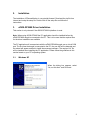
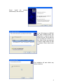
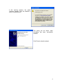
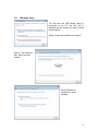
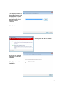
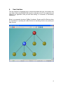
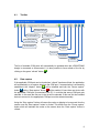
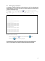
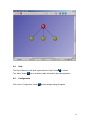
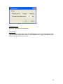
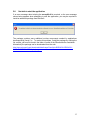
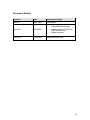
U
s
e
r ' s
G
u
i d
e
User's Guide
ZigBee Sensor Monitor
2008
SWRU157D
Low-Power RF
Contents
ZIGBEE SENSOR MONITOR................................................................................................................... 1
1.
INTRODUCTION ............................................................................................................................... 2
1.1.
1.2.
CC2530ZDK................................................................................................................................. 2
EZ430-RF2480.............................................................................................................................. 2
2.
INSTALLATION................................................................................................................................. 3
3.
EZ430-RF2480 DRIVER INSTALLATION ..................................................................................... 3
3.1.
3.2.
4.
WINDOWS XP ................................................................................................................................ 3
WINDOWS VISTA ........................................................................................................................... 6
USER INTERFACE ............................................................................................................................ 8
4.1.
TOOLBAR ....................................................................................................................................... 9
4.2.
DATA CAPTURE .............................................................................................................................. 9
4.3.
DATA LOGGING AND PLAYBACK .................................................................................................. 10
4.4.
HELP ............................................................................................................................................ 11
4.5.
CONFIGURATION .......................................................................................................................... 11
4.6.
NETWORK VIEW .......................................................................................................................... 13
4.6.1.
Zoom................................................................................................................................... 14
4.6.2.
Scroll bars .......................................................................................................................... 14
4.6.3.
Moving a Node ................................................................................................................... 14
4.6.4.
Removal of a Node ............................................................................................................. 14
4.7.
STATUS BAR ................................................................................................................................. 14
5.
TROUBLESHOOTING .................................................................................................................... 15
5.1.
5.2.
5.3.
5.4.
5.5.
5.6.
INCORRECT TEMPERATURE VALUES ............................................................................................. 15
STATUS OF THE CONNECTED DONGLE .......................................................................................... 15
MORE THAN ONE DONGLE CONNECTED TO THE PC ...................................................................... 15
CONNECT/DISCONNECT OTHER USB DEVICE ON SAME PC .......................................................... 15
USB DONGLE NOT AUTOMATICALLY DETECTED WHEN CONNECTED ............................................ 15
NOT ABLE TO START THE APPLICATION ........................................................................................ 17
DOCUMENT HISTORY........................................................................................................................... 18
1
1.
Introduction
ZigBee Sensor Monitor (or ZSensorMonitor1) is a PC application that will be used to
monitor the sensors in a ZigBee Network. ZSensorMonitor can be used together with
either the CC2530ZDK or an eZ430-RF2480 kit.
The network is formed when setting up the basic out of the box demo included either of
the kits. In the case of eZ430-RF2480 this includes the ZigBee Accelerator Sample
Application.
This document will only describe the user interface of the ZSensorDemo PC application.
1.1.
CC2530ZDK
Further details about the CC2530ZDK and the Sensor Demo sample application can be
found on the CC2530ZDK website:
www.ti.com/cc2530zdk
1.2.
eZ430-RF2480
Further details about the hardware platform and the ZigBee Accelerator Sample
Application (ZASA) can be found on the eZ430-RF2480 Demo kit website at
www.ti.com/eZ430-RF2480
1
Formerly known as eZ430-RF2480 Sensor Monitor.
2
2.
Installation
The installation of ZSensorMonitor is very straight forward. Download the zip file from
internet and unzip the setup file. Double click on the setup file and follow the
instructions.
3.
eZ430-RF2480 Driver Installation
This section is only relevant if the eZ430-RF2480 kit platform is used.
Note: When using eZ430-RF2480 the PC application should be installed before the
eZ430-RF2480 dongle is connected to the PC. This is to be sure that the required files
for the driver installation are available
The PC application will communicate with the eZ430-RF2480 dongle over a virtual COM
port. The first time the dongle is connected to the PC, the new HW will be detected and
the wizard will appear and ask to install the necessary software. The required “inf” file
will be installed when installing the PC application. Please follow the guidelines in this
section based on your PC’s operating system.
3.1.
Windows XP
When the dialog box appears, select
“No, not this time” and Click next.
3
Select
“Install
the
software
automatically” and click next.
If the IAR kickstart for MSP430
has been installed before this
application, it might be that this
dialog will pop up and ask the
user to select one of the two inf
files. Both inf files are equal and
it doesn’t matter which one that
is selected. Either should work
fine.
The installation will start without any
further selections.
4
If this warning appears, the option
“Continue Anyway” must be selected in
order to install the driver.
This dialog will be shown when
everything has been successfully
installed.
Click Finish to close the wizard.
5
3.2.
Windows Vista
The first time the USB dongle (sink) is
connected to the PC, the new HW is
detected and the system will ask to install
driver software.
Select “Locate and install driver software”.
Select “I don’t have the
disc. Show me other
options.”
Select “Browse my
computer for driver
software.”
6
The required “inf” file will
be installed together with
the application. Browse
to the directory of the
application and select
the sub directory
“Drivers”.
Click Next to continue.
Select “Install this driver software
anyway”
At the end the software
should be successfully
installed.
Click Close to end the
installation.
7
4.
User Interface
The user interface is developed to be as simple as possible with only a few buttons and
input fields. When the eZ430-RF2480 dongle is connected to the PC, the application will
search for an applicable COM port and start reading if a connection is successfully
established.
Below is a screenshot showing a ZigBee Coordinator, Routers and End Devices where
the Coordinator is operating as a data Sink and all remaining devices are operating as
data Sources.
8
4.1.
Toolbar
Drop down list with all
the available COM ports
Stop capturing data from
the serial COM port
Pause capturing data from
the serial COM port
Refresh list of serial
COM ports
Start logging to
file
Open log file for
playback
Start capturing data from
the serial COM port
Start playback
of log file
Configuration
Open application
user manual
About
information
The list of available COM ports will automatically be updated when the eZ430-RF2480
dongle is connected or disconnected. It is also possible to force refresh of the list by
clicking on the green “refresh” button
4.2.
.
Data capture
If the applicable COM port can be found when “refresh” has been clicked, the application
will automatically try to capture data from the COM port. If communication is successfully
established, the “capture” button
will be disabled and both the “Pause capture”
and the “Stop capture” button
will be enabled. If more than one device with
button
the applicable COM port is connected to the PC, it could be that wrong COM port gets
selected. In this case the first port in the list will be selected. If this was not the intended
device to connect to, the appropriate COM port must be selected manually.
Using the “Stop capture” button will cause the nodes on display to be removed from the
screen once the “Start capture” button is clicked. This differs from the “Pause capture”
button which will maintain the nodes on the screen when the “Start capture” button is
clicked.
9
4.3.
Data logging and playback
It is possible to capture the data traffic on the serial port to a log file for debugging and
playback purposes. The log file is pure ASCII text which displays a time-stamp and the
raw data in hexadecimal format.
Data logging is started by clicking the button
. The user will then be requested to
provide a file using the standard “File Save” dialog. The log file shown below is a sample
ZigBee PRO log file included in the distribution as “ZSensorMonitor_pro.log”.
15:30:27 02 61 01 41 00
15:30:45 03 46 82 01 00 58
15:30:45 0A 46 87 01 00 01 00 02 00 1e 1c 00 00
15:30:53 03 46 82 6f 79 19
15:30:55 0A 46 87 01 00 01 00 02 00 1f 1c 00 00
15:30:55 0A 46 87 6f 79 01 00 02 00 14 1e 00 00
15:31:03 03 46 82 70 79 19
15:31:04 0A 46 87 70 79 01 00 02 00 14 17 00 00
15:31:05 0A 46 87 01 00 01 00 02 00 20 1c 00 00
15:31:06 0A 46 87 70 79 01 00 02 00 14 17 00 00
15:31:12 03 46 82 71 79 58
15:31:12 0A 46 87 71 79 01 00 02 00 17 1d 00 00
15:31:15 0A 46 87 01 00 01 00 02 00 21 1c 00 00
15:31:16 0A 46 87 70 79 01 00 02 00 14 17 00 00
15:31:17 0A 46 87 6f 79 01 00 02 00 14 1e 00 00
Playback is done in two steps:
•
Open a log file using the
•
Click on the
button. This will active the
button.
button to start the playback
During playback the network view background will differ from when capturing data
online. The figure below is an example of playing back already recorded data.
10
4.4.
Help
The User’s Manual is a file which opens when the “help” button
The “About” button
4.5.
is clicked.
can be clicked to obtain information about the application.
Configuration
Click on the “Configuration” button
and the settings dialog will appear.
11
Temperature unit
Celsius or Fahrenheit can be selected.
Time interval
The timestamp of each node will be checked regularly to see if any message has been
received within the given time interval. If the elapsed time is longer than specified, the
Node will be removed from the screen.
12
4.6.
Network View
The PC demo will always display one node on the top of the screen, the Sink. Below the
Sink the presence of additional network nodes will be displayed as they are detected. Be
aware that nodes may place themselves on top of existing nodes when they first appear,
but can easily be dragged away with the mouse.
The various states of the nodes are described below.
Sink node not connected to the PC.
An attempt to read from the COM port has been made, but no response
received.
Sink node connected to the PC but reading from the COM port is not
active.
Sink node connected to the PC and reading from the COM port. The
difference with a Sink not connected to the PC can be seen from the black
and white outline.
A combined router and source node in the network. The short address,
temperature, voltage2 and a timestamp is shown within the node. The
timestamp is from the last message received from the node.
The node will blink each time a message is received by the connected
Sink node.
A dummy router. If we don’t receive any message from a router within the
configured time interval, it can be assumed that the node is out of service.
However, if the node has child nodes that are still alive, the node will not
be removed, it will be changed to a “dummy router”.
Source node with information about the short address, temperature,
2
Only applicable for the eZ430-RF2480.
13
voltage and a timestamp from when the last message was received from
this node.
The source node will blink each time a message is received by the
connected Sink node.
The role of each node is also indicated if the mouse is held over the node for more than
a second.
The nodes are connected with arrows to show the relationship between parent and child
nodes based on the CSKIP3 addressing scheme. This relationship is with respect to
addressing, and does not necessarily reflect the path taken for routing messages
between a source and the sink.
4.6.1.
Zoom
The user can zoom in and out of the network view by using the wheel on the mouse or
by clicking on the “+” or “-“ buttons. The focus for zooming in and out will be based on
the location of the mouse pointer.
4.6.2.
Scroll bars
The Horizontal and Vertical scroll bars can be used to navigate the network. If the
Network view is zoomed out far enough to make the outline of the rectangular
background visible, the scroll bar will disappear.
4.6.3.
Moving a Node
The nodes can be moved around with the mouse. To move a node, click and hold the
left mouse button while pointing to the node. Hold the left mouse button and drag the
node to the required position. Release the left mouse button when the node is in the
desired position.
4.6.4.
Removal of a Node
A node will be removed from the screen if no message has been received within the time
interval given in the settings dialog.
4.7.
Status bar
The status bar shows the status of the application; connection state, mode of operation,
serial port traffic statistics and protocol information.
3
Applies only to the ZigBee 2006 protocol used in eZ430-RF2480.
14
5.
Troubleshooting
5.1.
Incorrect temperature values
If the temperature is much different from the expected value, this is because the
temperature sensor is not calibrated.
5.2.
Status of the connected dongle
NB! This section only applies to the eZ430-RF2480.
It is possible for the status of the connected dongle to get out of synchronization if the
dongle gets disconnected and connected rapidly without any delay in between. In this
case the start/stop capturing data should be used manually to get the capture
operational again.
5.3.
More than one dongle connected to the PC
NB! This section only applies to the eZ430-RF2480.
If more than one dongle is connected to the PC, make sure that the correct dongle is
selected in the list of COM ports.
5.4.
Connect/Disconnect other USB device on same PC
NB! This section only applies to the eZ430-RF2480.
If any USB device is connected or disconnected while the eZ430-RF2480 dongle is
connected and Capture data is active, the capture of data could get deactivated. In this
case the Capture must be re-activated manually.
5.5.
USB dongle not automatically detected when connected
NB! This section only applies to the eZ430-RF2480.
If the eZ430-RF2480 dongle is not automatically detected, try to remove the dongle and
to connect it again. Windows is sometimes slow in detecting a new dongle so don’t do
this in quick succession..
It is also recommended to first start the PC application and then to plug-in the eZ430RF2480 dongle.
It is also possible to manually select the COM port from the drop down list. Search for
device starting with “MSP430…” and select this one. Then push the “capture” button to
establish the communication.
If still no success, it is time to check the device in the device manager. If the device
drivers have been successfully installed, there should be one Composite USB device
and one serial COM port.
Correctly installed devices should look like the screen shot below.
15
The serial COM port.
The composite device
When the eZ430-RF2480 is removed, these device drivers should disappear from the
view in the Device Manager. If they don’t disappear, a restart of the PC will be
necessary.
Check that the “MSP430” device is available in the drop down list of available COM
ports.
16
5.6.
Not able to start the application
If an error message about missing the msvcp80.dll is received, or the error message
shown below appears when attempting to start the application, you may be required to
install an additional package from Microsoft.
The package contains some additional runtime components needed by applications
developed with Visual C++. To resolve this problem, install the package by running the
file vcredist_x86.exe file found in the folder \vcredist of the ZSensorMonitor installation.
Alternatively the package can be downloaded from the web:
http://www.microsoft.com/downloads/details.aspx?familyid=9B2DA534-3E03-43918A4D-074B9F2BC1BF&displaylang=en
17
Document History
Revision
Date
Description/Changes
swru157
08/03/2008
Initial release.
swru157a
08/05/2009
•
•
•
•
swru157d
25/08/2009
Added logging and playback
Changed document name
Added support for CC2530 ZStack Sensor Demo
Added status bar
Changed document title
18
IMPORTANT NOTICE
Texas Instruments Incorporated and its subsidiaries (TI) reserve the right to make corrections, modifications,
enhancements, improvements,and other changes to its products and services at any time and to discontinue any product
or service without notice. Customers shouldobtain the latest relevant information before placing orders and should verify
that such information is current and complete. All products aresold subject to TI’s terms and conditions of sale supplied at
the time of order acknowledgment.
TI warrants performance of its hardware products to the specifications applicable at the time of sale in accordance with
TI’s standardwarranty. Testing and other quality control techniques are used to the extent TI deems necessary to support
this warranty. Except wheremandated by government requirements, testing of all parameters of each product is not
necessarily performed.
TI assumes no liability for applications assistance or customer product design. Customers are responsible for their
products andapplications using TI components. To minimize the risks associated with customer products and applications,
customers should provideadequate design and operating safeguards.
TI does not warrant or represent that any license, either express or implied, is granted under any TI patent right, copyright,
mask work right,or other TI intellectual property right relating to any combination, machine, or process in which TI products
or services are used. Information published by TI regarding third-party products or services does not constitute a license
from TI to use such products or services or a warranty or endorsement thereof. Use of such information may require a
license from a third party under the patents or other intellectual property of the third party, or a license from TI under the
patents or other intellectual property of TI.
Reproduction of TI information in TI data books or data sheets is permissible only if reproduction is without alteration and
is accompanied by all associated warranties, conditions, limitations, and notices. Reproduction of this information with
alteration is an unfair and deceptive business practice. TI is not responsible or liable for such altered documentation.
Information of third parties may be subject to additional restrictions.
Resale of TI products or services with statements different from or beyond the parameters stated by TI for that product or
service voids all express and any implied warranties for the associated TI product or service and is an unfair and
deceptive business practice. TI is not responsible or liable for any such statements.
TI products are not authorized for use in safety-critical applications (such as life support) where a failure of the TI product
would reasonably be expected to cause severe personal injury or death, unless officers of the parties have executed an
agreement specifically governing such use. Buyers represent that they have all necessary expertise in the safety and
regulatory ramifications of their applications, and acknowledge and agree that they are solely responsible for all legal,
regulatory and safety-related requirements concerning their products and any use of TI products in such safety-critical
applications, notwithstanding any applications-related information or support that may be provided by TI. Further, Buyers
must fully indemnify TI and its representatives against any damages arising out of the use of TI products in such safetycritical applications.
TI products are neither designed nor intended for use in military/aerospace applications or environments unless the TI
products are specifically designated by TI as military-grade or "enhanced plastic." Only products designated by TI as
military-grade meet military specifications. Buyers acknowledge and agree that any such use of TI products which TI has
not designated as military-grade is solely at the Buyer's risk, and that they are solely responsible for compliance with all
legal and regulatory requirements in connection with such use.
TI products are neither designed nor intended for use in automotive applications or environments unless the specific TI
products are designated by TI as compliant with ISO/TS 16949 requirements. Buyers acknowledge and agree that, if they
use any non-designated products in automotive applications, TI will not be responsible for any failure to meet such
requirements.
Following are URLs where you can obtain information on other Texas Instruments products and application solutions:
Products
Amplifiers
Data Converters
DSP
Clocks and Timers
Interface
Logic
Power Mgmt
Microcontrollers
RFID
RF/IF and ZigBee® Solutions
amplifier.ti.com
dataconverter.ti.com
dsp.ti.com
www.ti.com/clocks
interface.ti.com
logic.ti.com
power.ti.com
microcontroller.ti.com
www.ti-rfid.com
www.ti.com/lprf
Applications
Audio
Automotive
Broadband
Digital Control
Medical
Military
Optical Networking
Security
Telephony
Video & Imaging
Wireless
www.ti.com/audio
www.ti.com/automotive
www.ti.com/broadband
www.ti.com/digitalcontrol
www.ti.com/medical
www.ti.com/military
www.ti.com/opticalnetwork
www.ti.com/security
www.ti.com/telephony
www.ti.com/video
www.ti.com/wireless
Mailing Address: Texas Instruments, Post Office Box 655303, Dallas, Texas 75265
Copyright 2008, Texas Instruments Incorporated
19