1
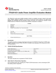
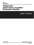
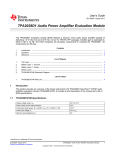
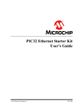
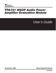
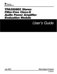
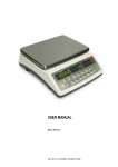
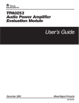
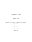
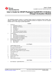
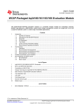
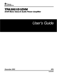
User's Guide
SLOU174A – February 2005 – Revised April 2005
TPA2012D2 Audio Power Amplifier Evaluation Module
The TPA2012D2 audio power amplifier evaluation module is a complete, low-power,
Class-D, stereo audio power amplifier capable of delivering 1.2 W/channel (YZH
package). All components and the evaluation module are Pb-Free.
Contents
Introduction ..........................................................................................
Operation ............................................................................................
Reference ............................................................................................
Related Documentation From Texas Instruments ..............................................
1
2
3
4
1
2
3
6
List of Figures
TPA2012D2 Output Power ........................................................................
Top Layer ............................................................................................
Bottom Layer ........................................................................................
TPA2012D2 EVM Schematic Diagram ..........................................................
1
2
3
4
2
4
4
5
List of Tables
Gain Settings ........................................................................................ 3
TPA2012D2 EVM Parts List ....................................................................... 6
1
2
1
Introduction
This section provides an overview of the Texas Instruments (TI) TPA2012D2 NanoFree™ WCSP audio
amplifier evaluation module (TPA2012D2 EVM). It includes a brief description of the module and a list of
EVM specifications.
1.1
TPA2012D2 EVM Specifications
Supply voltage range, VDD
2.5 V to 5.5 V
Power supply current rating required
2.5 A
Continuous output power, PO: 4-Ω BTL, VDD = 5 V
1.2 W (see note)
Audio input voltage, VI
0 V to VDD
Minimum load impedance, ZL
4Ω
Note:
The TPA2012D2 in the RTJ package (QFN) is rated at 2.1 W/channel. The YZH package
(WCSP) is thermally limited to 1.2 W/channel on the EVM. For layouts with higher trace
density and additional copper, the maximum output power will be larger. See the data
sheet for device descriptions.
NanoFree is a trademark of Texas Instruments.
SLOU174A – February 2005 – Revised April 2005
TPA2012D2 Audio Power Amplifier Evaluation Module
1
www.ti.com
Operation
2.50
PO − Output Power − W
See Note
VDD = 2.5 V, 1%
2
VDD = 2.5 V, 10%
VDD = 3.6 V, 1%
1.50
VDD = 3.6 V, 10%
VDD = 5 V, 1%
VDD = 3.6 V, 10%
1
0.50
0
4
9
14
19
24
29
34
RL − Load Resistance − Figure 1. TPA2012D2 Output Power
Note:
The dashed portion of the curve indicates the region where the TPA2012D2YZH (WCSP)
is thermally limited. Output power in this region will depend on the heat dissipation
provided by the circuit board. TPA2012D2RTJ (QFN) is not thermally limited and can
achieve output power along both the solid and dashed portions of the curves.
2
Operation
This section describes how to operate the TPA2012D2 EVM.
2.1
Quick Start for Stand-Alone Operation
Use the following steps when operating the TPA2012D2 EVM standalone or when connecting the EVM
into existing circuits or equipment.
2.1.1
2.1.2
Power and Ground
1. Ensure the external power sources are set to OFF.
2. Set the power supply voltage between 2.5 V and 5.5 V. When connecting the power supply to the
EVM, make sure to attach the ground connection to the GND header pin first and then connect the
positive supply to the VDD header pin. Verify that the connections are made to the correct header pins.
Inputs and Outputs
2.1.2.1
Audio
1. Ensure that the audio source is set to the minimum level.
2. Connect the audio source to the inputs, INL+/- and INR+/-.
– For a differential audio source, connect the audio source directlty to the appropriate input header
pins.
– For a single-ended audio source, connect the audio source to the negative input header pin of the
appropriate channel and ground the positive audio input header pin.
3. Connect speakers (4 Ω?32 Ω) to the output pins, OUTL+/- and OUTR+/-.
2.1.2.2
Gain Control
1. The GAIN0 and GAIN1 jumpers control the gain setting of the TPA2012D2. With the jumpers installed,
the G0 and G1 pins are pulled to ground. See Table 1 for gain setting values.
2
TPA2012D2 Audio Power Amplifier Evaluation Module
SLOU174A – February 2005 – Revised April 2005
www.ti.com
Reference
Table 1. Gain Settings
Amplifier Gain Setting (typ)
(1)
GAIN1 (1)
GAIN0 (1)
V/V
0
0
2
6
0
1
4
12
1
0
8
18
1
1
16
24
dB
0 = Jumper installed, 1 = Jumper not installed
2.1.2.3
Shutdown Controls
1. The TPA2012D2 provides independent shutdown controls so that each channel can be controlled
separately. The shutdown pins, SDL and SDR, are active low. This means that a low voltage (ground)
on this pin places the appropriate channel in shutdown mode. Using the pushbuttons provided on the
EVM, the TPA2012D2 can be placed in shutdown by pressing and holding the button(s) down. Both
buttons must be depressed in order for both channels of the TPA2012D2 to turn off. When the buttons
are released, the appropriate channel on the device restarts.
2. The jumper J1 can be used to tie SDL and SDR signals together. With jumper J1 installed, both
channels can be placed in shutdown by pressing either SDL or SDR. This is the default configuration
of the EVM.
2.2
Power Up
1. Verify the correct connections as described in Sections 2.1.1 and 2.1.2.
2. Verify the voltage setting of the power supply is between 2.5 V and 5.5 V and turn ON the power
supply. Proper operation of the EVM should begin.
3. Adjust the audio signal source as needed.
3
Reference
This section includes the EVM schematic, parts list, and board layout reference.
SLOU174A – February 2005 – Revised April 2005
TPA2012D2 Audio Power Amplifier Evaluation Module
3
www.ti.com
Reference
3.1
TPA2012D2 EVM PCB Layers
Figure 2. Top Layer
Figure 3. Bottom Layer
4
TPA2012D2 Audio Power Amplifier Evaluation Module
SLOU174A – February 2005 – Revised April 2005
www.ti.com
Reference
3.2
TPA2012D2 EVM Schematic Diagram
VDD
VDD
R4
120 k
VDD
R3
120 k
GAIN1
C12
10 F
GAIN0
C9
10 F
(Not Populated)
VDD
VDD
1 F
C7
1 F
C8
1 F
G0
PVDD
C6
L4
INL+
OUTL+
INL−
OUTL−
INR−
OUTR−
INR+
OUTR+
PGND
1 F
SDR
INR−
C5
AGND
INL−
AVDD
G1
U1
SDL
INL+
C11
0.1 F
C10
1 F
OUTL+
C4
1 nF
L3
OUTL−
INR+
C3
1 nF
VDD
R1
120 k
L2
OUTR−
SDR
C2
1 nF
VDD
SDR
JP1
R2
120 k
L1
OUTR+
SDL
C1
1 nF
SDL
Figure 4. TPA2012D2 EVM Schematic Diagram
SLOU174A – February 2005 – Revised April 2005
TPA2012D2 Audio Power Amplifier Evaluation Module
5
www.ti.com
Related Documentation From Texas Instruments
3.3
TPA2012D2 Audio Power Amplifer Evaluation Module Parts List
Table 2. TPA2012D2 EVM Parts List
Part No.
4
Size
Qty.
C1-C4
Capacitor, Ceramic, 1 nF, 50V, X7R
0402
4
TDK C1005X7R1H102
C5-C8, C10
Capacitor, Ceramic, 1 µF, 6.3V, Y5V
0402
5
TDK C1005Y5VOJ105
C11
Capacitor, Ceramic, 0.1 µF, 6.3V, X5R
0402
1
TDK C1005X5R1A104
C12
Capacitor, Ceramic, 10 µF, 10V, Y5V
0805
1
TDK C2012Y5V1A106
C9
Capacitor (Do not populate)
0805
1
R1-R4
Resistor, 120 K, 1/16W, 1%
0402
2
Pb-free
SDL, SDR
Momentary switch
2
Panasonic, EVQ-PPBA25
U1
TPA2012D2 audio amplifier IC WCSP
1
TI
QFN
TPA2012D2 QFN package
Vendor Part Number
TI
GAIN0, GAIN1, Jumper, Position, 2 mm Header
J1
3
Norcomp 2163-36-01-P2
PNP
HEADERS
Terminal post headers
12
Sullins, PTC36SABN
SAMTEC TSW-19-8-G-S
L1-L4
Ferrite Bead
4
TDK MPZ1608S221A
PCB
TPA2012D2 EVM printed circuit board
0603
1
Related Documentation From Texas Instruments
•
6
Description
TPA2012D2 2.1-W Stereo Filter-Free Class-D Audio Power Amplifier (SLOS438) This is the data
sheet for the TPA2012D2 audio amplifier integrated circuit.
TPA2012D2 Audio Power Amplifier Evaluation Module
SLOU174A – February 2005 – Revised April 2005
FCC Warnings
This equipment is intended for use in a laboratory test environment only. It generates, uses, and can radiate radio frequency
energy and has not been tested for compliance with the limits of computing devices pursuant to subpart J of part 15 of FCC rules,
which are designed to provide reasonable protection against radio frequency interference. Operation of this equipment in other
environments may cause interference with radio communications, in which case the user at his own expense will be required to
take whatever measures may be required to correct this interference.
EVM IMPORTANT NOTICE (CATEGORY B)
IMPORTANT: TI is providing the enclosed TPA2012D2 evaluation module under the following conditions:
This evaluation module (EVM) being provided by Texas Instruments (TI) is intended for use for ENGINEERING DEVELOPMENT
OR EVALUATION PURPOSES ONLY and is not considered by Texas Instruments to be fit for commercial use. As such, this EVM
may not be complete in terms of design and/or manufacturing related protective considerations including product safety measures
typically found in the end-product incorporating the module. As a prototype, this product does not fall within the scope of the
European Union Directive on electromagnetic compatibility and on low voltage and therefore may not meet the technical
requirements of the directive. This EVM is not subject to the EU marking requirements.
• Should this EVM not meet the specifications indicated in the User’s Guide the EVM may be returned within 30 days
from the date of delivery for a full refund. THE FOREGOING WARRANTY IS THE EXCLUSIVE WARRANTY MADE BY
TI AND IS IN LIEU OF ALL OTHER WARRANTIES, EXPRESSED, IMPLIED, OR STATUTORY, INCLUDING ANY
WARRANTY OF MERCHANTABILITY OR FITNESS FOR ANY PARTICULAR PURPOSE.
• The user assumes all responsibility and liability for proper and safe handling of the EVM. The user acknowledge that the use
of the EVM could present serious hazards and that it is the user’s responsibility to take all precautions for the handling and
use of the EVMs in accordance with good laboratory practices. Please be aware that the products received may not be
regulatory compliant or agency certified (FCC, UL, etc.). Due to the open construction of the product, it is the user’s
responsibility to take any and all appropriate precautions with regard to electrostatic discharge.
• NEITHER PARTY WILL BE LIABLE TO THE OTHER FOR ANY INDIRECT, SPECIAL, INCIDENTAL, OR CONSEQUENTIAL DAMAGES.
• TI is currently dealing with various customers for products, and therefore our arrangement with the user will not be
exclusive.
• TI assumes no liability for applications assistance, customer product design, software performance, or infringement
of patents or services described herein.
• Please read the User’s Guide and specifically the section in the User’s Guide pertaining to warnings and restrictions prior to
handling the product. This section contains important information regarding high temperature and voltages which TI
recommends to be read before handling the EVMs. In case of any doubt regarding safety, please contact the TI application
engineer.
• Persons handling the product should have electronics training and observe good laboratory practice standards.
• No license is granted under any patent right or other intellectual property right of TI covering or relating to any combination,
machine, or process in which such TI products or services might be or are used.
• This Agreement is subject to the laws of the State of Texas, excluding the body of conflicts of laws and the United Nations
Convention on the International Sale of Goods, and will be subject to the exclusive jurisdiction of the courts of the State of
Texas.
EVM WARNINGS AND RESTRICTIONS
It is important to operate this EVM within the input voltage range of 2.5 V to 5 V and the output voltage range of xxx V to xxx V.
Exceeding the specified input range may cause unexpected operation and/or irreversible damage to the EVM. If there are
questions concerning the input range, please contact a TI field representative prior to connecting the input power.
Applying loads outside of the specified output range may result in unintended operation and/or possible permanent damage to the
EVM. Please consult the EVM User's Guide prior to connecting any load to the EVM output. If there is uncertainty as to the load
specification, please contact a TI field representative.
During normal operation, some circuit components may have case temperatures greater than 60ï½ C. The EVM is designed to
operate properly with certain components above 60ï½ C as long as the input and output ranges are maintained. These
components include but are not limited to linear regulators, switching transistors, pass transistors, and current sense resistors.
These types of devices can be identified using the EVM schematic located in the EVM User's Guide. When placing measurement
probes near these devices during operation, please be aware that these devices may be very warm to the touch.
Mailing Address: Texas Instruments, Post Office Box 655303, Dallas, Texas 75265
Copyright © 2004, Texas Instruments Incorporated
IMPORTANT NOTICE
Texas Instruments Incorporated and its subsidiaries (TI) reserve the right to make corrections, modifications, enhancements,
improvements, and other changes to its products and services at any time and to discontinue any product or service without notice.
Customers should obtain the latest relevant information before placing orders and should verify that such information is current and
complete. All products are sold subject to TI’s terms and conditions of sale supplied at the time of order acknowledgment.
TI warrants performance of its hardware products to the specifications applicable at the time of sale in accordance with TI’s
standard warranty. Testing and other quality control techniques are used to the extent TI deems necessary to support this
warranty. Except where mandated by government requirements, testing of all parameters of each product is not necessarily
performed.
TI assumes no liability for applications assistance or customer product design. Customers are responsible for their products and
applications using TI components. To minimize the risks associated with customer products and applications, customers should
provide adequate design and operating safeguards.
TI does not warrant or represent that any license, either express or implied, is granted under any TI patent right, copyright, mask
work right, or other TI intellectual property right relating to any combination, machine, or process in which TI products or services
are used. Information published by TI regarding third-party products or services does not constitute a license from TI to use such
products or services or a warranty or endorsement thereof. Use of such information may require a license from a third party under
the patents or other intellectual property of the third party, or a license from TI under the patents or other intellectual property of TI.
Reproduction of information in TI data books or data sheets is permissible only if reproduction is without alteration and is
accompanied by all associated warranties, conditions, limitations, and notices. Reproduction of this information with alteration is an
unfair and deceptive business practice. TI is not responsible or liable for such altered documentation.
Resale of TI products or services with statements different from or beyond the parameters stated by TI for that product or service
voids all express and any implied warranties for the associated TI product or service and is an unfair and deceptive business
practice. TI is not responsible or liable for any such statements.
TI products are not authorized for use in safety-critical applications (such as life support) where a failure of the TI product would
reasonably be expected to cause severe personal injury or death, unless officers of the parties have executed an agreement
specifically governing such use. Buyers represent that they have all necessary expertise in the safety and regulatory ramifications
of their applications, and acknowledge and agree that they are solely responsible for all legal, regulatory and safety-related
requirements concerning their products and any use of TI products in such safety-critical applications, notwithstanding any
applications-related information or support that may be provided by TI. Further, Buyers must fully indemnify TI and its
representatives against any damages arising out of the use of TI products in such safety-critical applications.
TI products are neither designed nor intended for use in military/aerospace applications or environments unless the TI products are
specifically designated by TI as military-grade or "enhanced plastic." Only products designated by TI as military-grade meet military
specifications. Buyers acknowledge and agree that any such use of TI products which TI has not designated as military-grade is
solely at the Buyer's risk, and that they are solely responsible for compliance with all legal and regulatory requirements in
connection with such use.
TI products are neither designed nor intended for use in automotive applications or environments unless the specific TI products
are designated by TI as compliant with ISO/TS 16949 requirements. Buyers acknowledge and agree that, if they use any
non-designated products in automotive applications, TI will not be responsible for any failure to meet such requirements.
Following are URLs where you can obtain information on other Texas Instruments products and application solutions:
Products
Applications
Amplifiers
amplifier.ti.com
Audio
www.ti.com/audio
Data Converters
dataconverter.ti.com
Automotive
www.ti.com/automotive
DSP
dsp.ti.com
Broadband
www.ti.com/broadband
Interface
interface.ti.com
Digital Control
www.ti.com/digitalcontrol
Logic
logic.ti.com
Military
www.ti.com/military
Power Mgmt
power.ti.com
Optical Networking
www.ti.com/opticalnetwork
Microcontrollers
microcontroller.ti.com
Security
www.ti.com/security
RFID
www.ti-rfid.com
Telephony
www.ti.com/telephony
Low Power
Wireless
www.ti.com/lpw
Video & Imaging
www.ti.com/video
Wireless
www.ti.com/wireless
Mailing Address: Texas Instruments, Post Office Box 655303, Dallas, Texas 75265
Copyright © 2007, Texas Instruments Incorporated