1
PIC32 Ethernet Starter Kit
User’s Guide
© 2010 Microchip Technology Inc.
DS61166A
Note the following details of the code protection feature on Microchip devices:
•
Microchip products meet the specification contained in their particular Microchip Data Sheet.
•
Microchip believes that its family of products is one of the most secure families of its kind on the market today, when used in the
intended manner and under normal conditions.
•
There are dishonest and possibly illegal methods used to breach the code protection feature. All of these methods, to our
knowledge, require using the Microchip products in a manner outside the operating specifications contained in Microchip’s Data
Sheets. Most likely, the person doing so is engaged in theft of intellectual property.
•
Microchip is willing to work with the customer who is concerned about the integrity of their code.
•
Neither Microchip nor any other semiconductor manufacturer can guarantee the security of their code. Code protection does not
mean that we are guaranteeing the product as “unbreakable.”
Code protection is constantly evolving. We at Microchip are committed to continuously improving the code protection features of our
products. Attempts to break Microchip’s code protection feature may be a violation of the Digital Millennium Copyright Act. If such acts
allow unauthorized access to your software or other copyrighted work, you may have a right to sue for relief under that Act.
Information contained in this publication regarding device
applications and the like is provided only for your convenience
and may be superseded by updates. It is your responsibility to
ensure that your application meets with your specifications.
MICROCHIP MAKES NO REPRESENTATIONS OR
WARRANTIES OF ANY KIND WHETHER EXPRESS OR
IMPLIED, WRITTEN OR ORAL, STATUTORY OR
OTHERWISE, RELATED TO THE INFORMATION,
INCLUDING BUT NOT LIMITED TO ITS CONDITION,
QUALITY, PERFORMANCE, MERCHANTABILITY OR
FITNESS FOR PURPOSE. Microchip disclaims all liability
arising from this information and its use. Use of Microchip
devices in life support and/or safety applications is entirely at
the buyer’s risk, and the buyer agrees to defend, indemnify and
hold harmless Microchip from any and all damages, claims,
suits, or expenses resulting from such use. No licenses are
conveyed, implicitly or otherwise, under any Microchip
intellectual property rights.
Trademarks
The Microchip name and logo, the Microchip logo, dsPIC,
KEELOQ, KEELOQ logo, MPLAB, PIC, PICmicro, PICSTART,
PIC32 logo, rfPIC and UNI/O are registered trademarks of
Microchip Technology Incorporated in the U.S.A. and other
countries.
FilterLab, Hampshire, HI-TECH C, Linear Active Thermistor,
MXDEV, MXLAB, SEEVAL and The Embedded Control
Solutions Company are registered trademarks of Microchip
Technology Incorporated in the U.S.A.
Analog-for-the-Digital Age, Application Maestro, CodeGuard,
dsPICDEM, dsPICDEM.net, dsPICworks, dsSPEAK, ECAN,
ECONOMONITOR, FanSense, HI-TIDE, In-Circuit Serial
Programming, ICSP, Mindi, MiWi, MPASM, MPLAB Certified
logo, MPLIB, MPLINK, mTouch, Omniscient Code
Generation, PICC, PICC-18, PICDEM, PICDEM.net, PICkit,
PICtail, REAL ICE, rfLAB, Select Mode, Total Endurance,
TSHARC, UniWinDriver, WiperLock and ZENA are
trademarks of Microchip Technology Incorporated in the
U.S.A. and other countries.
SQTP is a service mark of Microchip Technology Incorporated
in the U.S.A.
All other trademarks mentioned herein are property of their
respective companies.
© 2010, Microchip Technology Incorporated, Printed in the
U.S.A., All Rights Reserved.
Printed on recycled paper.
ISBN: 978-1-60932-721-7
Microchip received ISO/TS-16949:2002 certification for its worldwide
headquarters, design and wafer fabrication facilities in Chandler and
Tempe, Arizona; Gresham, Oregon and design centers in California
and India. The Company’s quality system processes and procedures
are for its PIC® MCUs and dsPIC® DSCs, KEELOQ® code hopping
devices, Serial EEPROMs, microperipherals, nonvolatile memory and
analog products. In addition, Microchip’s quality system for the design
and manufacture of development systems is ISO 9001:2000 certified.
DS61166A-page 2
© 2010 Microchip Technology Inc.
PIC32 ETHERNET STARTER
KIT USER’S GUIDE
Table of Contents
Preface ........................................................................................................................... 5
Chapter 1. Introduction
1.1 Kit Contents .................................................................................................. 11
1.2 PIC32 Functionality and Features ................................................................ 12
Chapter 2. Hardware
2.1 Hardware Features ....................................................................................... 15
Appendix A. Board Layout and Schematics
A.1 PIC32 Ethernet Starter Kit Block Diagram ................................................... 19
A.2 PIC32 Ethernet Starter Kit Board Layout ..................................................... 20
A.3 PIC32 Ethernet Starter Kit Board Schematics ............................................. 22
Appendix B. Bill of Materials
Index ............................................................................................................................. 31
Worldwide Sales and Service .................................................................................... 32
© 2010 Microchip Technology Inc.
DS61166A-page 3
PIC32 Ethernet Starter Kit User’s Guide
NOTES:
DS61166A-page 4
© 2010 Microchip Technology Inc.
PIC32 ETHERNET STARTER
KIT USER’S GUIDE
Preface
NOTICE TO CUSTOMERS
All documentation becomes dated, and this manual is no exception. Microchip tools and
documentation are constantly evolving to meet customer needs, so some actual dialogs
and/or tool descriptions may differ from those in this document. Please refer to our web site
(www.microchip.com) to obtain the latest documentation available.
Documents are identified with a “DS” number. This number is located on the bottom of each
page, in front of the page number. The numbering convention for the DS number is
“DSXXXXXA”, where “XXXXX” is the document number and “A” is the revision level of the
document.
For the most up-to-date information on development tools, see the MPLAB® IDE online help.
Select the Help menu, and then Topics to open a list of available online help files.
INTRODUCTION
This chapter contains general information that will be useful to know before using the
PIC32 Ethernet Starter Kit. Items discussed in this chapter include:
•
•
•
•
•
•
•
Document Layout
Conventions Used in this Guide
Recommended Reading
The Microchip Web Site
Development Systems Customer Change Notification Service
Customer Support
Document Revision History
DOCUMENT LAYOUT
This document describes how to use the PIC32 Ethernet Starter Kit (all also referred
to as “starter kit”) as a development tool to emulate and debug firmware on a target
board. This user’s guide is composed of the following chapters:
• Chapter 1. “Introduction” provides a brief overview of the starter kit, highlighting
its features and uses.
• Chapter 2. “Hardware” provides the hardware descriptions of the starter kit.
• Appendix A. “Board Layout and Schematics” provides a block diagram, board
layouts, and detailed schematics of the starter kit.
© 2010 Microchip Technology Inc.
DS61166A-page 5
PIC32 Ethernet Starter Kit User’s Guide
CONVENTIONS USED IN THIS GUIDE
This manual uses the following documentation conventions:
DOCUMENTATION CONVENTIONS
Description
Represents
Examples
Arial font:
Italic characters
Initial caps
Referenced books
MPLAB® IDE User’s Guide
Emphasized text
...is the only compiler...
A window
the Output window
A dialog
the Settings dialog
A menu selection
select Enable Programmer
Quotes
A field name in a window or dialog “Save project before build”
Underlined, italic text with right
angle bracket
A menu path
File>Save
Bold characters
A dialog button
Click OK
A tab
Click the Power tab
A key on the keyboard
Press <Enter>, <F1>
Sample source code
#define START
Filenames
autoexec.bat
File paths
C:\mcc18\h
Keywords
_asm, _endasm, static
Command-line options
-Opa+, -Opa-
Bit values
0, 1
Constants (in source code)
0xFF, ‘A’
Italic Courier New
A variable argument
file.o, where file can be any
valid filename
Square brackets [ ]
Optional arguments
mcc18 [options] file
[options]
Curly brackets and pipe
character: { | }
Choice of mutually exclusive
arguments; an OR selection
errorlevel {0|1}
Ellipses...
Replaces repeated text
var_name [, var_name...]
Text in angle brackets < >
Courier New font:
Plain Courier New
Represents code supplied by user void main (void)
{ ...
}
DS61166A-page 6
© 2010 Microchip Technology Inc.
Preface
RECOMMENDED READING
This user’s guide describes how to use the starter kit. The following Microchip
documents are available and recommended as supplemental reference resources.
PIC32MX5XX/6XX/7XX Family Data Sheet (DS61156)
Refer to this document for detailed information on PIC32 devices. Reference
information found in this data sheet includes:
•
•
•
•
Device memory maps
Device pinout and packaging details
Device electrical specifications
List of peripherals included on the devices
MPLAB® C Compiler for PIC32 User’s Guide (DS51686)
This document, formerly the “MPLAB C32 C Compiler for PIC32 User’s Guide”, details
the use of Microchip’s MPLAB C Compiler for PIC32 to develop an application.
MPLAB® IDE User’s Guide (DS51519)
Refer to this document for more information pertaining to the installation and
implementation of the MPLAB IDE software, as well as the MPLAB Editor and MPLAB
SIM Simulator software that are included with it.
Universal Serial Bus Specification and Associated Documents
The Universal Serial Bus is defined by the USB 2.0 specification and its associated
supplements and class-specific documents. These documents are available from the
USB Implementers Forum. See their web site at: http://www.usb.org
THE MICROCHIP WEB SITE
Microchip provides online support via our web site at http://www.microchip.com. This
web site makes files and information easily available to customers. Accessible by most
Internet browsers, the web site contains the following information:
• Product Support – Data sheets and errata, application notes and sample
programs, design resources, user’s guides and hardware support documents,
latest software releases and archived software
• General Technical Support – Frequently Asked Questions (FAQs), technical
support requests, online discussion groups, Microchip consultant program
member listings
• Business of Microchip – Product selector and ordering guides, latest Microchip
press releases, listings of seminars and events; and listings of Microchip sales
offices, distributors and factory representatives
© 2010 Microchip Technology Inc.
DS61166A-page 7
PIC32 Ethernet Starter Kit User’s Guide
DEVELOPMENT SYSTEMS CUSTOMER CHANGE NOTIFICATION SERVICE
Microchip’s customer notification service helps keep customers current on Microchip
products. Subscribers will receive e-mail notification whenever there are changes,
updates, revisions or errata related to a specified product family or development tool of
interest.
To register, access the Microchip web site at http://www.microchip.com, click
Customer Change Notification and follow the registration instructions.
The Development Systems product group categories are:
• Compilers – The latest information on Microchip C compilers and other language
tools. These include the MPLAB® C compiler; MPASM™ and MPLAB 16-bit
assemblers; MPLINK™ and MPLAB 16-bit object linkers; and MPLIB™ and
MPLAB 16-bit object librarians.
• Emulators – The latest information on the Microchip MPLAB REAL ICE™
in-circuit emulator.
• In-Circuit Debuggers – The latest information on the Microchip in-circuit
debugger, MPLAB ICD 3.
• MPLAB IDE – The latest information on Microchip MPLAB IDE, the Windows®
Integrated Development Environment for development systems tools. This list is
focused on the MPLAB IDE, MPLAB SIM simulator, MPLAB IDE Project Manager
and general editing and debugging features.
• Programmers – The latest information on Microchip programmers. These include
the MPLAB PM3 device programmer and the PICkit™ 3 development
programmers.
CUSTOMER SUPPORT
Users of Microchip products can receive assistance through several channels:
•
•
•
•
Distributor or Representative
Local Sales Office
Field Application Engineer (FAE)
Technical Support
Customers should contact their distributor, representative or field application engineer
(FAE) for support. Local sales offices are also available to help customers. A listing of
sales offices and locations is included in the back of this document.
Technical support is available through the web site at: http://support.microchip.com
DS61166A-page 8
© 2010 Microchip Technology Inc.
Preface
DOCUMENT REVISION HISTORY
Revision A (December 2010)
This is the initial release of the PIC32 Ethernet Starter Kit User’s Guide.
© 2010 Microchip Technology Inc.
DS61166A-page 9
PIC32 Ethernet Starter Kit User’s Guide
NOTES:
DS61166A-page 10
© 2010 Microchip Technology Inc.
PIC32 ETHERNET STARTER
KIT USER’S GUIDE
Chapter 1. Introduction
Thank you for purchasing a Microchip Technology PIC32 Ethernet Starter Kit. This
board provides a low-cost, modular development system for Microchip’s line of 32-bit
microcontrollers.
The starter kit comes preloaded with demonstration software for the user to explore the
new features of the PIC32. It is also expandable through a modular expansion interface, which allows the user to extend its functionality. The starter kit also supplies
on-board circuitry for full debug and programming capabilities.
This chapter covers the following topics:
• Kit Contents
• PIC32 Functionality and Features
The preprogrammed example code on the PIC32 MCU is available via download from
the Microchip web site at http://www.microchip.com. All project files have been included
so that the code may be used directly to restore the PIC32 MCU on the starter kit to its
original state (i.e., if the sample device has been reprogrammed with another program)
or so you can use the tutorial code as a platform for further experimentation.
1.1
KIT CONTENTS
The PIC32 Ethernet Starter Kit contains the following items:
• PIC32 Ethernet Starter Kit development board
• USB mini-B to full-sized A cable – USB debug cable to debug and power the
board
• USB micro-B to full-sized A cable – PIC32 USB cable to communicate with the
PIC32 USB port
• RJ-45 CAT5 Ethernet patch cable – Ethernet CAT5 cable to communicate with the
PIC32 Ethernet port
Note:
© 2010 Microchip Technology Inc.
If you are missing any part of a kit, contact a Microchip sales office for assistance. A list of Microchip offices for sales and service is provided on the
back page of this document.
DS61166A-page 11
PIC32 Ethernet Starter Kit User’s Guide
1.2
PIC32 FUNCTIONALITY AND FEATURES
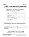
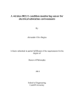
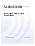
Representations of the layout of the PIC32 Ethernet Starter Kit are shown in Figure 1-1
and Figure 1-2.
The top assembly of the board includes these key features, as indicated in Figure 1-1:
1.
2.
3.
4.
5.
6.
7.
8.
9.
10.
11.
12.
13.
14.
15.
PIC32MX795F512L 32-bit microcontroller.
PIC32MX440F512H USB microcontroller for on-board debugging.
Green power indicator LED.
On-board crystal for precision microcontroller clocking (8 MHz).
USB connectivity for on-board debugger communications.
Orange debug indicator LED.
Three push button switches for user-defined inputs.
Three user-defined indicator LEDs.
USB Type A receptacle connectivity for PIC32 host-based applications.
HOST mode power jumper.
RJ-45 Ethernet port.
Ethernet 10/100 bus speed indicator LED.
50 MHz Ethernet PHY oscillator.
32 kHz oscillator (optional).
USB Host and OTG power supply for powering PIC32 USB applications.
Note:
When running self-powered USB device applications, open the jumper JP2
to prevent possibly back-feeding voltage onto the VBUS from one port on
the host to another (or from one host to another).
For details on these features, refer to Chapter 2. “Hardware”.
FIGURE 1-1:
PIC32 ETHERNET STARTER KIT LAYOUT (TOP SIDE)
12
11
8
13
7
6
8
7
1
5
8
14
2
7
4
9
15
10
DS61166A-page 12
3
© 2010 Microchip Technology Inc.
Introduction
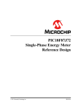
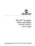
The bottom assembly of the board includes these key features, as indicated in
Figure 1-2:
1. Regulated +3.3V power supply for powering the starter kit via USB or expansion
board.
2. Connector for various expansion boards.
3. USB Type micro-AB receptacle for OTG and USB device connectivity for PIC32
OTG/device-based applications.
4. External Ethernet PHY.
FIGURE 1-2:
PIC32 ETHERNET STARTER KIT LAYOUT (UNDERSIDE)
4
2
3
1
© 2010 Microchip Technology Inc.
DS61166A-page 13
PIC32 Ethernet Starter Kit User’s Guide
NOTES:
DS61166A-page 14
© 2010 Microchip Technology Inc.
PIC32 ETHERNET STARTER
KIT USER’S GUIDE
Chapter 2. Hardware
This chapter describes the hardware features of the PIC32 Ethernet Starter Kit.
2.1
HARDWARE FEATURES
The key features of the PIC32 Ethernet Starter Kit are listed below. They are presented
in the order given in Section 1.2 “PIC32 Functionality and Features”. You can refer
to Figure 1-1 for their locations on the board.
2.1.1
Processor Support
The PIC32 Ethernet Starter Kit is designed with a permanently mounted (i.e., soldered)
PIC32MX795F512L processor.
2.1.2
Power Supply
There are two ways to supply power to the PIC32 Ethernet Starter Kit:
• USB bus power connected to USB debug connector J1.
• An external application board with a regulated DC power supply that provides +5V
can be connected to the J2 application board connector that is provided on the
bottom side of the board.
One green LED (D3) is provided to show that the PIC32 microcontroller is powered up.
2.1.3
Debug USB Connectivity
The PIC32 Ethernet Starter Kit includes a PIC32MX440F512H USB microcontroller
that provides debugger connectivity over USB. The PIC32MX440F512H is hard-wired
to the PIC32 device to provide two types of protocol translation:
• I/O pins of PIC32MX440F512H to the ICSP™ pins of the PIC32
• I/O pins of PIC32MX440F512H to the JTAG pins of the PIC32
The PIC32 Ethernet Starter Kit currently uses the JTAG pins of the PIC32 device for
programming and debugging.
2.1.4
PIC32 USB Connectivity
There are three possible ways to connect to the PIC32 USB microcontroller:
• HOST Mode
Connect the device to the Type A connector J4, located on the top side of the
starter kit. If using the Debug USB port to power the Host port, install jumper JP2
to short the back-power prevention diode. Note that a maximum of ~400 mA can
be supplied from the Debug USB port to the Host port using this method.
If the full 500 mA supply is needed, an external supply must be connected to the
application board and jumper JP2 must be removed to prevent back-powering the
Debug USB port.
© 2010 Microchip Technology Inc.
DS61166A-page 15
PIC32 Ethernet Starter Kit User’s Guide
• DEVICE Mode
First, connect the debug mini-B USB cable to port J1. Next, connect the starter kit
to the host using a cable with a Type-B micro-plug to the starter kit’s micro-A/B
port J5, located on the bottom side of the starter kit. The other end of the cable
must have a Type-A plug. Connect it to a USB host. Jumper JP2 should be
removed.
• OTG Mode
Connect the starter kit to the OTG device using an OTG micro-A/B cable to the
micro-A/B port J5, located on the bottom side of the starter kit. The starter kit provides an on-board power supply capable of providing 120 mA Max. This supply is
controlled by the PIC32MX795F512L microcontroller. Jumper JP2 should be
removed.
2.1.5
Switches
Push button switches provide the following functionality:
• SW1: Active-low switch connected to RD6
• SW2: Active-low switch connected to RD7
• SW3: Active-low switch connected to RD13
The switches do not have any debounce circuitry and require the use of internal pull-up
resistors; this allows you to investigate software debounce techniques. When Idle, the
switches are pulled high (+3.3V). When pressed, they are grounded.
2.1.6
LEDs
The RD0 through RD2 LEDs are connected to PORTD of the processor. The PORTD
pins are set high to light the LEDs.
2.1.7
Oscillator Options
The installed microcontroller has an oscillator circuit connected to it. The main oscillator
uses an 8 MHz crystal (Y2) and functions as the controller’s primary oscillator. Use of an
external crystal is required to develop USB applications. The USB specification dictates
a frequency tolerance of ±0.25% for full speed. Non-USB applications can use the
internal oscillators. The starter kit also has provisions for an external secondary 32 kHz
oscillator (Y3); however, this is not populated. A suitable oscillator, the ECS-3X8, can be
obtained from Digi-Key: Part no. X801-ND CMR200TB32.768KDZFTR.
The PIC32MX440F512H is independently clocked and has its own 8 MHz crystal (Y1).
2.1.8
120-Pin Modular Expansion Connector
The PIC32 Ethernet Starter Kit has been designed with a 120-pin modular expansion
interface, which allows the board to provide basic generic functionality now, and easy
extendability to new technologies as they become available.
TABLE 2-1:
STARTER KIT CONNECTOR PART NUMBERS
Connector
DS61166A-page 16
HIROSE Electric PN
Starter Kit Connector
FX10A-120P/12-SV1(71)
Application Board Connector
FX10A-120S/12-SV(71)
© 2010 Microchip Technology Inc.
Hardware
2.1.9
Ethernet PHY
The PIC32 Ethernet Starter Kit has been designed with a National DP83848 PHY for
connecting the starter kit using an RJ-45 cable to a network. The interface between the
PHY and the PIC32 has been configured for the industry standard RMII interface and
has been isolated from the Modular Expansion Connector. LED D8 indicates the
Ethernet bus speed. When lit, the bus speed is 100 Mbps; when off, the bus speed is
10 Mbps.
© 2010 Microchip Technology Inc.
DS61166A-page 17
PIC32 Ethernet Starter Kit User’s Guide
NOTES:
DS61166A-page 18
© 2010 Microchip Technology Inc.
PIC32 ETHERNET STARTER
KIT USER’S GUIDE
Appendix A. Board Layout and Schematics
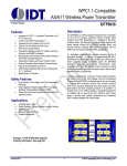
A.1
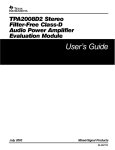
PIC32 ETHERNET STARTER KIT BLOCK DIAGRAM
FIGURE A-1:
HIGH-LEVEL BLOCK DIAGRAM OF THE PIC32 ETHERNET STARTER KIT
Power Circuit
USB OTG
Device/OTG
(Type micro-A/B)
+3.3V
Power
Supply
VUSB(1) or
+5V_EXT
Host
(Type A)
Debug USB
Debugger Circuit
ICSP™
JTAG
+5V EXT
(PIC32MX440F512H)
PIC32MX795F512L
Application Board Connector
USB Host
Switches
LEDs
Ethernet
PHY
10/100 Jack
Note 1:
From Debugger USB Port.
© 2010 Microchip Technology Inc.
DS61166A-page 19
PIC32 Ethernet Starter Kit User’s Guide
A.2
PIC32 ETHERNET STARTER KIT BOARD LAYOUT
FIGURE A-2:
DS61166A-page 20
PIC32 ETHERNET STARTER KIT LAYOUT (TOP ASSEMBLY)
© 2010 Microchip Technology Inc.
Board Layout and Schematics
FIGURE A-3:
PIC32 ETHERNET STARTER KIT LAYOUT (BOTTOM ASSEMBLY)
© 2010 Microchip Technology Inc.
DS61166A-page 21
PIC32 Ethernet Starter Kit User’s Guide
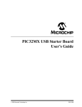
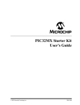
A.3
PIC32 ETHERNET STARTER KIT BOARD SCHEMATICS
FIGURE A-4:
PIC32 ETHERNET STARTER KIT (ETHERNET)
J1
J2
J3
J4
J5
J6
J7
J8
DS61166A-page 22
© 2010 Microchip Technology Inc.
PIC32 ETHERNET STARTER KIT (PIC32 DEVICE)
© 2010 Microchip Technology Inc.
FIGURE A-5:
Board Layout and Schematics
DS61166A-page 23
PIC32 Ethernet Starter Kit User’s Guide
PIC32 ETHERNET STARTER KIT (USB HOST AND OTG POWER SUPPLIES)
DS61166A-page 24
FIGURE A-6:
© 2010 Microchip Technology Inc.
PIC32 ETHERNET STARTER KIT (DEBUGGER)
© 2010 Microchip Technology Inc.
FIGURE A-7:
Board Layout and Schematics
DS61166A-page 25
PIC32 Ethernet Starter Kit User’s Guide
PIC32 ETHERNET STARTER KIT (3.3V POWER SUPPLY)
DS61166A-page 26
FIGURE A-8:
© 2010 Microchip Technology Inc.
Board Layout and Schematics
FIGURE A-9:
PIC32 ETHERNET STARTER KIT (APPLICATION BOARD CONNECTOR)
© 2010 Microchip Technology Inc.
DS61166A-page 27
PIC32 Ethernet Starter Kit User’s Guide
NOTES:
DS61166A-page 28
© 2010 Microchip Technology Inc.
PIC32 ETHERNET STARTER
KIT USER’S GUIDE
Appendix B. Bill of Materials
TABLE B-1:
PIC32 ETHERNET STARTER KIT BILL OF MATERIALS
Reference
Description
Manufacturer
Part No.
U4
IC SMT, MCP1253, DC/DC Converter 3.3V 8L
MSOP
Microchip
MCP1253-33X50I/MS
U1
IC SMT, PIC32MX440F512H-80I/MR 64P QFN
Microchip
PIC32MX440F512H-80I/MR
U2
IC SMT, PIC32MX795F512L 100L TQFP
Microchip
PIC32MX795F512L-80I/PT
U5
IC SMT, TC1262-3.3VDB, SOT-223
Microchip
TC1262-3.3VDBTR
C1, C9-C14, CAP SMT, 0.1 µF 0603 CER 16V 10% X7R
C27, C28,
C30-C33,
C35-C39
Panasonic
ECJ-1VB1C104K
C17
CAP SMT, 1.0 µF 0805 CER 16V 10% X7R
Kemet
C0805C105K4RACTU
C2, C29,
C34
CAP SMT, 10 µF 0805 CER 6.3V 20% , X5R
Panasonic
ECJ-2FB0J106M
C7, C8, C18 CAP SMT, 4.7 µF 0805 CER 16V +80-20% Y5V
Panasonic
ECJ-2FB0J475K
C3-C6
CAP SMT, 20 pF 0603 CER 50V, 5% C0G
Rohm
MCH185A200JK
C25
CAP SMT, 6.8 µF 0805 CER 6.3V 10% X5R
Kemet
C0805C685K9PACTU
C26
CAP SMT, 100 µF 1812 CER 6.3V -20%,+80% Y5V Panasonic
ECJ-5YF0J107Z
JP2
CONN, HDR, 1x2 Breakaway, 0.100" Pitch, 0.025
SQ Post (0.100"/0.230")
TSW-102-07-G-S
Samtec
CONN, Shunt, 2-pin Shorting Shunt (.100" Spacing) Sullins
SSC02SYAN
J1
CONN SMT, RECPT, USB Mini-B 5POS RA
Delphi
15430262-110
J2
CONN, SMT, HDR, 120P, w/Post
Hirose Electronics
J4
CONN, RECPT, USB Type-A w/Board Lock
FCI
J5
CONN, RECPT, USB Micro-B SMD TH SHLL
Hirose Electronics ZX62D-AB-5P8
D2, D7
Diode SMT, Schottky 30V 0.5A SOD-123
On Semiconductor MBR0530T1G
U6
IC SMT, TPS20X1 .75A Power DIST Switch
5-SOT23
Texas Instruments TPS2051BDBVR
U3
IC SMT, TPS2041 1A PWR DIST Switch SNGL
SOT23-5
Texas Instruments TPS2041BDBVR
LED1
LED SMT, 0805 Red DIFF 2x1.25 mm Thin
Lumex
SML-LXT0805IW-TR
D1, LED2
LED SMT, 0805 Yellow DIFF 2x1.25 mm Thin
Lumex
SML-LXT0805YW-TR
D3, D8,
LED3
LED SMT, 0805 Green DIFF 2x1.25 mm
Lumex
SML-LXT0805GW-TR
Y1, Y2
OSC SMT, Crystal 8.000 MHz 18 pF SMD
Abracon Corp.
ABM3B-8.000MHZ-B2-T
R4, R9,
R11, R12
RES SMT, 1.0 KΩ 1/10W 5% 0603
Panasonic
ERJ-3GEYJ102V
R10, R13,
R14, R16,
R18
RES SMT, 4.7 KΩ 1/10W 5% 0603
Panasonic
ERJ-3GEYJ472V
© 2010 Microchip Technology Inc.
87520-0010BLF
DS61166A-page 29
PIC32 Ethernet Starter Kit User’s Guide
TABLE B-1:
PIC32 ETHERNET STARTER KIT BILL OF MATERIALS (CONTINUED)
Reference
Description
Manufacturer
Part No.
R5, R19,
R20, R22,
R23
RES SMT, 330Ω 1/10W 5% 0603
Panasonic
ERJ-3GEYJ331V
R17
RES SMT, 100 KΩ 1/10W 1% 0603
Panasonic
PANASONIC
ERJ-3EKF1003V
S1-S3
Switch, Light Touch 160 gF
Panasonic
EVQ-PPBA25
J6
CONN, MAGJACK 1PORT SHLD 10/100BT and
LEDs
Bel Stewart
SI-60062-F
U8
IC SMT, TXRX Ethernet PHYTER 48-LQFP
National
DP83848CVV/NOPB
Y4
OSC SMT, Oscillator 50.0000 MHz 3.3V
AVX
ECS-80-20-5PVX
R55, R56
RES SMT, 1.5 KΩ 1/10W 1% 0603
Panasonic
ERJ-3EKF1501V
R15, R21,
R25, R33,
R51, R57
RES SMT, 2.2 KΩ 1/16W 1% 0603
SPC Technology
MC0603WGF2201T5E-TC
R29,
R59-R63
RES SMT, 33Ω 1/10W 5% 0603
Panasonic
ERJ-3GEYJ330V
R37,
R39-R41
RES SMT, 49.9Ω 1/10W 1% 0603
Rohm
MCR03EZPFX49R9
R28, R44
RES SMT, 249Ω 1/10W 1% 0603
Yageo
RC0603FR-07249RL
R26
RES SMT, 510Ω 1/16W 1% 100 PPM 0603
Yageo/Phyco
9C06031A5100FKHFT
R50
RES SMT, 4.87 KΩ 1/10W 1% 0603
Yageo
RC0603FR-074K87L
Spare Location, Do Not Install
C18, C15,
C16, GND1,
J3, R24,
R27, TP9,
TP10, TP11,
Y3
DS61166A-page 30
—
—
© 2010 Microchip Technology Inc.
PIC32 ETHERNET STARTER
KIT USER’S GUIDE
Index
C
S
Customer Change Notification Service ...................... 8
Customer Support ...................................................... 8
Starter Kit Board
Block Diagram................................................... 19
Starter Kit Layout
Bottom Assembly ........................................ 13, 21
Top Assembly ............................................. 12, 20
Starter Kit Schematics
3.3V Power Supply ........................................... 26
Application board connector ............................. 27
Debugger .......................................................... 25
Ethernet ............................................................ 22
PIC32 device..................................................... 23
USB Host and OTG power supplies ................. 24
D
Documentation
Conventions ........................................................ 6
H
Hardware Features
LEDs ............................................................15, 16
Oscillator Options ............................................. 16
PICtail Plus Card Edge Connectors.................. 16
Power Supply.................................................... 15
Processor Support ............................................ 15
Switches ........................................................... 16
USB Connectivity .............................................. 15
U
USB
Connectivity ...................................................... 15
I
W
Internet Address......................................................... 7
WWW Address........................................................... 7
M
Microchip Internet Web Site ....................................... 7
MPLAB IDE Simulator, Editor User’s Guide............... 7
P
PIC32
Layout
32-bit microcontroller ................................. 12
Debug indicator LED ................................. 12
Ethernet 10/100 Bus Speed LED .............. 12
Ethernet PHY oscillator ............................. 12
Expansion board connector ....................... 13
External Ethernet PHY .............................. 13
HOST mode power jumper ........................ 12
On-board crystal ........................................ 12
Optional 32 kHz oscillator .......................... 12
Power supply ............................................. 13
Power-indicator LED.................................. 12
RJ-45 Ethernet port ................................... 12
Switches .................................................... 12
USB connectivity ....................................... 12
USB Host and OTG power supply ............. 12
USB microcontroller................................... 12
USB Type A receptacle ............................. 12
USB Type micro-AB receptacle ................. 13
User-defined LEDs .................................... 12
© 2010 Microchip Technology Inc.
DS61166A-page 31
Worldwide Sales and Service
AMERICAS
ASIA/PACIFIC
ASIA/PACIFIC
EUROPE
Corporate Office
2355 West Chandler Blvd.
Chandler, AZ 85224-6199
Tel: 480-792-7200
Fax: 480-792-7277
Technical Support:
http://support.microchip.com
Web Address:
www.microchip.com
Asia Pacific Office
Suites 3707-14, 37th Floor
Tower 6, The Gateway
Harbour City, Kowloon
Hong Kong
Tel: 852-2401-1200
Fax: 852-2401-3431
India - Bangalore
Tel: 91-80-3090-4444
Fax: 91-80-3090-4123
India - New Delhi
Tel: 91-11-4160-8631
Fax: 91-11-4160-8632
Austria - Wels
Tel: 43-7242-2244-39
Fax: 43-7242-2244-393
Denmark - Copenhagen
Tel: 45-4450-2828
Fax: 45-4485-2829
India - Pune
Tel: 91-20-2566-1512
Fax: 91-20-2566-1513
France - Paris
Tel: 33-1-69-53-63-20
Fax: 33-1-69-30-90-79
Japan - Yokohama
Tel: 81-45-471- 6166
Fax: 81-45-471-6122
Germany - Munich
Tel: 49-89-627-144-0
Fax: 49-89-627-144-44
Atlanta
Duluth, GA
Tel: 678-957-9614
Fax: 678-957-1455
Boston
Westborough, MA
Tel: 774-760-0087
Fax: 774-760-0088
Chicago
Itasca, IL
Tel: 630-285-0071
Fax: 630-285-0075
Cleveland
Independence, OH
Tel: 216-447-0464
Fax: 216-447-0643
Dallas
Addison, TX
Tel: 972-818-7423
Fax: 972-818-2924
Detroit
Farmington Hills, MI
Tel: 248-538-2250
Fax: 248-538-2260
Kokomo
Kokomo, IN
Tel: 765-864-8360
Fax: 765-864-8387
Los Angeles
Mission Viejo, CA
Tel: 949-462-9523
Fax: 949-462-9608
Santa Clara
Santa Clara, CA
Tel: 408-961-6444
Fax: 408-961-6445
Toronto
Mississauga, Ontario,
Canada
Tel: 905-673-0699
Fax: 905-673-6509
Australia - Sydney
Tel: 61-2-9868-6733
Fax: 61-2-9868-6755
China - Beijing
Tel: 86-10-8528-2100
Fax: 86-10-8528-2104
China - Chengdu
Tel: 86-28-8665-5511
Fax: 86-28-8665-7889
Korea - Daegu
Tel: 82-53-744-4301
Fax: 82-53-744-4302
China - Chongqing
Tel: 86-23-8980-9588
Fax: 86-23-8980-9500
Korea - Seoul
Tel: 82-2-554-7200
Fax: 82-2-558-5932 or
82-2-558-5934
China - Hong Kong SAR
Tel: 852-2401-1200
Fax: 852-2401-3431
Malaysia - Kuala Lumpur
Tel: 60-3-6201-9857
Fax: 60-3-6201-9859
China - Nanjing
Tel: 86-25-8473-2460
Fax: 86-25-8473-2470
Malaysia - Penang
Tel: 60-4-227-8870
Fax: 60-4-227-4068
China - Qingdao
Tel: 86-532-8502-7355
Fax: 86-532-8502-7205
Philippines - Manila
Tel: 63-2-634-9065
Fax: 63-2-634-9069
China - Shanghai
Tel: 86-21-5407-5533
Fax: 86-21-5407-5066
Singapore
Tel: 65-6334-8870
Fax: 65-6334-8850
China - Shenyang
Tel: 86-24-2334-2829
Fax: 86-24-2334-2393
Taiwan - Hsin Chu
Tel: 886-3-6578-300
Fax: 886-3-6578-370
China - Shenzhen
Tel: 86-755-8203-2660
Fax: 86-755-8203-1760
Taiwan - Kaohsiung
Tel: 886-7-213-7830
Fax: 886-7-330-9305
China - Wuhan
Tel: 86-27-5980-5300
Fax: 86-27-5980-5118
Taiwan - Taipei
Tel: 886-2-2500-6610
Fax: 886-2-2508-0102
China - Xian
Tel: 86-29-8833-7252
Fax: 86-29-8833-7256
Thailand - Bangkok
Tel: 66-2-694-1351
Fax: 66-2-694-1350
Italy - Milan
Tel: 39-0331-742611
Fax: 39-0331-466781
Netherlands - Drunen
Tel: 31-416-690399
Fax: 31-416-690340
Spain - Madrid
Tel: 34-91-708-08-90
Fax: 34-91-708-08-91
UK - Wokingham
Tel: 44-118-921-5869
Fax: 44-118-921-5820
China - Xiamen
Tel: 86-592-2388138
Fax: 86-592-2388130
China - Zhuhai
Tel: 86-756-3210040
Fax: 86-756-3210049
08/04/10
DS61166A-page 32
© 2010 Microchip Technology Inc.