1
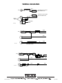
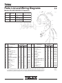
Telex
®
Parts List and Wiring Diagrams
Models PH-45/PH-85/PH-87 Headsets
Model No.
PH-45
Catalog No.
64437-001
PH-85
64437-005
PH-87
64437-004
ITEM
NO.
1
2
3
4
5
6
7
8
9
10
11
12
13
14
15
16
17
18
Receiver Type &
Impedance (Ohms)
Microphone Type &
Impedance (Ohms)
Dynamic, 600
Carbon, 20
Magnetic
Left 275, Right 625
Magnetic
Left 275, Right 625
Carbon, 20
MODEL/QTY
DESCRIPTION
Headband Assy
Headband Spacer
Slider Tip
Headpad
Earcup-Yoke-Slider Assy,
Boom Side1
Earcup-Yoke-Slider Assy,
Boomless Side1
Boom Arm-Ball Half-Cord Kit2
Strain Relief
Strain Relief
Coil Cord Assy, Unterminated
Coil Cord Assy w/PTT Switch,
Complete
Switch Housing, Front
Switch Housing
Screw, No. 2-56 x 1/2
Button
Spring Pin
Switch, SPST
Y-Cord Assy w/Plugs
Clothing Clip
Retainer
Carbon, 20
PART NO.
ITEM
NO.
PH-45
1
1
2
1
1
PH-85
1
1
2
1
1
PH-87
1
1
2
1
1
61162-044
63709-000
61166-005
63801-000
70398-028
19
20
21
22
23
1
1
1
70398-027
1
1
NA
NA
NA
1
NA
1
1
NA
1
1
NA
NA
1
70398-004
63456-007
63465-005
19652-032
19693-003
24
25
26
27
28
29
30
NA
NA
NA
NA
NA
NA
1
1
1
NA
NA
NA
NA
NA
NA
NA
NA
1
1
1
4
1
2
1
NA
NA
1
62981-000
63176-000
51856-003
62979-000
50087-181
54578-000
60074-111
63097-002
02852-000
31
32
33
34
35
MODEL/QTY
DESCRIPTION
Housing, Mic Bottom
Mic Element-Housing Assy
Adapter Cap
Screw, No. 6-20 x 1/4
Terminal
Terminal
Cord Assy, Overhead
Strain Relief
Ball Half3
Ball Joint Spring
Hex Spacer
Foam Liner
Foam-Rcvr Element-Boot Assy
Foam-Rcvr Element-Boot Assy,
Boom Side
Foam-Rcvr Element-Boot Assy,
Boomless Side
Screw, No. 4-40 x 1/4
Ear plate
Screw, No. 4-40 x 1/4
Ear Cushion
Ear Cushion Cover
1 One (1) slider tip (item no. 3) is supplied with this part. Slider tip should be glued to slider using an epoxy adhesive.
2 Kit contains one (1) boom arm, one (1) boom cord, and one (1) ball half preassembled with installation instructions.
3 Quantity two (2) required per Headset, but one (1) is supplied as part of boom arm-ball half-cord kit (Item No. 6).
®
PART NO.
PH-45
1
1
1
1
1
NA
1
2
1
1
2
2
2
NA
PH-85
1
1
1
1
NA
1
1
2
1
1
2
2
NA
1
PH-87
1
1
1
1
1
NA
1
2
1
1
2
2
NA
1
61614-011
70398-005
61564-012
51856-008
54462-000
54462-001
60051-189
63488-001
63451-002
63453-000
57907-000
63763-000
70398-017
70398-020
NA
1
1
70398-019
4
2
4
2
2
4
2
4
2
2
4
2
4
2
2
51856-024
63751-000
51845-038
63444-000
35772-000
19693, B
63502, A6
61171, AZ1
64437, Y
35772-000
WIRING DIAGRAMS
BLU
MIC
0.250-INCH (6.35 mm)DIA
RED PHONE PLUG
WHT
0.250-INCH (6.35 mm)DIA
BLACK PHONE PLUG
L
PHASE
MARK
WHT
OVERHEAD
CORD
R
A9-134/2
RED
WHT
MIC
BLK
L
WHT
GRN
R
WHT
A9-134/3
OVERHEAD CORD
RED
WHT
MIC
RED
BLK
L
NO NC
C
BLK
WHT
WHT
R
WHT
GRN
A9-134/4
OVERHEAD CORD
38109-134 Rev E
April 1999