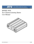
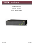
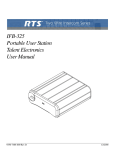
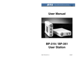
1
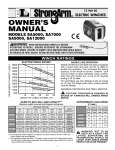
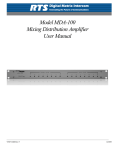
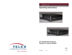
UHF Log Periodic Antenna
Order No. 71147000
PN802573
8601 East Cornhusker Highway, P.O. Box 5579, Lincoln NE 68505
INSTRUCTION MANUAL
General Description
The ALP-450 is a broadband directional log periodic antenna. It will receive any frequency from
450 to 900 MHz. The “gain” of this antenna enables it to receive signals from a greater distance
than a typical “whip” type antenna.
Log Periodic Antennas are also directional (like a
TV antenna) and will have the best reception when
pointed at the transmitter. This yields the benefit of
less interference from unwanted signals coming
from the back or side of the antenna.
SPECIFICATIONS
(average)
Gain ..................................................................................................................4.6 dBd
1/2 Power Beam Width .........................................................................................120°
Front-to-Back Ratio...........................................................................................19.4 dB
SWR.......................................................................................................................1.5:1
Input Impedance ................................................................................................50 ohm
Input Connector ....................................................................................................TNC
Antenna Placement
The ALP-450 should be placed in a position that
has a clear view of the transmitter(s) for best results. Obstructions such as walls, ceilings, and
metal objects will reduce range and performance.
Antenna Mounting
The ALP-450 is supplied with a variety of mounting hardware. It should always be mounted vertically with the arrows pointing toward the
transmitter(s). See Figure 1.
Figure 1
Antenna Mounting
-1-
Microphone Stand Adaptor
Attach the microphone stand adaptor using the
screws and spacers supplied with it. See Figure 2.
Figure 2
Microphone Stand Adaptor
Angle Bracket
Attach the angle bracket using the nuts,
lockwashers, and screws supplied with it. Self tapping screws are supplied for securing the bracket to
wood, metal, or other surfaces. See Figure 3.
Figure 3
Angle Bracket
-2-
Clamps
Clamps are provided for mounting the ALP-450 on
pipes, scaffolds, tree limbs, etc.. Attach the clamps
with the hardware supplied. See Figure 4.
Figure 4
Clamps
Do not clamp the antenna to horizontal metal
objects that extend past the clamp. See Figure 5.
This will detune the antenna and cause loss of
range and performance.
GOOD
Figure 5
Clamp Mounting
-3-
BAD
Coax Cable
For best results, it is recommended that cable losses
be kept under 4 dB. (Every 3 dB of signal loss results in a system operating distance reduction of
25%).
See the accessories section of this manual for special low loss cable assemblies.
MOUNTING SUGGESTIONS
Mic Boom
Mic Stand
Wall
Top Surface
-4-
Pipe or Scaffold
Tree Limb
Combination:
Bracket with Clamps
-5-
ACCESSORIES
Special Low Loss Antenna Cables with
TNC Connects
Length
Part No.
10 Ft. (3 meters)
25 Ft. (7.6 meters)
50 Ft. (15 meters)
75 Ft. (23 meters)
100 Ft. (30 meters)
690419
71151-025
71151-050
71151-075
71151-100
PRINTED IN U.S.A.
Copyright© 1995 by Telex
TELEX COMMUNICATIONS, INC.
All rights reserved.
20 Sept 1995
-6-