1
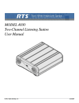
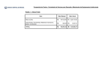
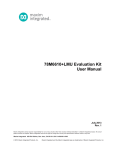
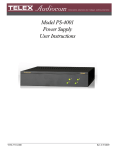
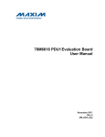
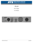
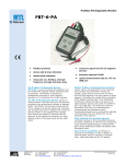
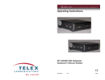
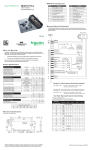
IFB-325
Portable User Station
Talent Electronics
User Manual
9350-7488-000 Rev D
12/2005
PROPRIETARY NOTICE
Shipping to the Manufacturer
The RTS product information and design disclosed herein were originated by and
are the property of Telex Communications, Inc. Telex reserves all patent, proprietary design, manufacturing, reproduction, use and sales rights thereto, and to any
article disclosed therein, except to the extent rights are expressly granted to others.
All shipments of products should be made via UPS Ground, prepaid (you may
request from Factory Service a different shipment method). Any shipment
upgrades will be paid by the customer. The equipment should be shipped in the
original packing carton. If the original carton is not available, use any suitable
container that is rigid and of adequate size. If a substitute container is used, the
equipment should be wrapped in paper and surrounded with at least four inches of
excelsior or similar shock-absorbing material. All shipments must be sent to the
following address and must include the Proof of Purchase for warranty repair.
Upon completion of any repair the equipment will be returned via United Parcel
Service or specified shipper, collect.
COPYRIGHT NOTICE
Copyright 2005 by Telex Communications, Inc. All rights reserved. Reproduction
in whole or in part without prior written permission from Telex is prohibited.
UNPACKING AND INSPECTION
Immediately upon receipt of the equipment, inspect the shipping container and
the contents carefully for any discrepancies or damage. Should there be any,
notify the freight company and the dealer at once.
CUSTOMER SUPPORT
Technical questions should be directed to:
Customer Service Department
RTS/Telex Communication Inc.
12000 Portland Avenue South.
Burnsville, MN 55337 U.S.A.
Telephone: (800) 392-3497
Fax: (800) 323-0498
Factory Service: (800) 553-5992
Return Shipping Instructions
Customer Service Department
Telex Communications, Inc. (Lincoln, Nebraska)
Telephone: (402) 467-5321
Fax: (402) 467-3279
Factory Service: (800) 553-5992
Please include a note in the box which supplies the company name, address,
phone number, and a person to contact regarding the repair, the type and quantity
of equipment, a description of the problem and the serial number(s).
Factory Service Department
Telex Communications, Inc.
8601 East Cornhusker Hwy.
Lincoln, NE 68507, U.S.A
Attn: Service
Table
of
Contents
Chapter 1
Introduction and Description ......................................................................................................................3
Description and Specifications ....................................................................................................................3
General ........................................................................................................................................................3
Features .......................................................................................................................................................3
Connections and Controls ...........................................................................................................................3
Specifications ..............................................................................................................................................4
Chapter 2
Operation ....................................................................................................................................................5
External Connections and Controls ............................................................................................................5
Internal Jumper ...........................................................................................................................................6
Chapter 3
Replacement Parts .......................................................................................................................................7
Where to Obtain Parts .................................................................................................................................7
Mechanical Parts .........................................................................................................................................7
Chapter 4
Diagrams .....................................................................................................................................................9
CHAPTER 1
Introduction and Description
Description and Specifications
General
the IFB-325 is a portable user station for use with RTS 2-wire intercom systems. The IFB-325 is a listen-only IFB belt pack
that can be used to listen to only one intercom channel.
Features
Features of the IFB-325 include:
•
•
•
•
Powered externally, via the intercom system power supply on channel one
Power-ON indicator
Headset/earset jack set for 150Ω operation
Internal jumper selection of intercom channel one or channel two (default to channel two)
Connections and Controls
The IFB-325 has the following connections and controls:
• Intercom/program volume control
• Headset connector that accepts 1/4” monaural phone plug
• Channel connector that accepts an XLR type 3-pin connector for intercom line an power input
3
Introduction and Description
Specifications
General
Channel Supplied Power Requirements
32 VDC nominal (standard RTS line), 50 to 80 mA
Environmental Requirements
Storage: -20°C to 80°C; 0% to 95% humidity, non-condensing
Operating: 0°C to 50°C; 0% to 95% humidity, non-condensing
Dimensions
3.25” (82.6mm)H x 3.5” (88.mm)W x 1.8” (45.7mm) D
Weight
1.0 pounds (0.45kg)
Interface Requirements
Earset
150 to 600Ω headphones
RTS Intercom Channel
Input Level: 2 Vp-p (0 dBu) nominal
Input Impedance: 200Ω ±5%
Noise Contribution
less than -60 dB on the line
Headphone Amplifier
Voltage Gain
27 ±3dB from the line
Maximum Output
165mW into 150Ω
Frequency Response
250 Hz to 8 kHz +1/-4dB
Connector Pin Configurations
Headset Connector
Type: 1/4” Monaural Plug
Sleeve:
Tip:
Headset audio low
Headset audio high
Intercom Channel Connectors
Type: XLR-3F
Pin 1
Pin 2
Pin 3
4
Common
Intercom Channel 1 (audio and +32 VDC input)
Intercom Channel 2 (audio)
CHAPTER 2
Operation
External Connections and Controls
1
2
3
4
5
HEADSET
IFB-325
FIGURE 1.
IFB-325 Connections and Controls
NOTE: The numbers refer to the callouts in Figure 1.
1.
Volume Control: Use this control to adjust the headset/earset listen level.
2.
ON indicator: This LED glows green when the belt pack is connected to an intercom channel that is functioning.
3.
Headset Connector: This connector accepts a wide-response headset/earset, such as the RTS Model 2233 or Model 2234,
with a 1/4” monaural phone plug.
4.
Hole Plug: This hole is for future use.
5.
Intercom Channel Connectors: The IFB-325 intercom channel is connected via a 3-pin female connector. The IFB-325 is
powered from the intercom system power supply and will turn ON with the intercom system.
5
Operation
Internal Jumper
The channel termination is set for operation on intercom channel two, which is compatible with other RTS equipment. If IFB operation is required on the intercom channel one, an internal jumper must be changed as described
in Table 1.
To gain access to the jumper, disconnect all power and line connections. Remove two screws from the top of
each side and two screws from the bottom of each side. The jumper location is shown in Figure 2.
J1
C8
C6
J2
R12
C10
J3
C18
DS1
C12
FIGURE 2.
Internal Jumper
JUMPER
NUMBER
J3
JUMPER FUNCTION
IFB Channel Selectilon
Pin 4&5 shorted: Channel one IFB
Pins 2 & 3
shorted
Pin 2&3 shorted: Channel two IFB
(Channel 2)
TABLE 1. Internal
6
DEFAULT
SETTING
Jumper
CHAPTER 3
Replacement Parts
Where to Obtain Parts
Final Assembly
(Refer to Figure X for Item No. location
Parts may be obtained directly from Telex at:
Item No.
Telex/RTS Systems
12000 Portland Avenue South
Burnsville, MN 55337
Telephone: (800) 392-3497
Fax: (800) 323-0498
Description
Part No.
14
Loctite Superbonder
BF 753
15
Label, Serial
3101001700
16
Not Used
17
Not Used
18
Screw Locking Agent
59857-000
Mechanical Parts
Final Assembly
(Refer to Figure X for Item No. location
Item No.
Description
Connector Plate Assembly
(Refer to figure X for Item No. locations)
Item No.
Description
Part No.
1
Not Used
Part No.
1
Case, IFB-325
90607374-008
2
Jack, Phono,1/4”
2013001200
2
Top Plate
90707374-008
3
Connector, XLR-3F
40055-10
3
Not Used
4
Connector, 4-pin
59958-004
4
Circuit Board Assembly
90307477-001
5
Contact, Connector
59958-200
5
Knot, Nylon Body
9160563-601
6 thru 9
6
Boot, Knob
9160563-602
10
Connector Plate
90807374-007
7
Screw, 4-40 x 0.25, Flat Head
800124-001
11
Screw Locking Agent
59857-000
8
Belt Clip
91107600-00
9
Screw, 4-40 x 0.25, Pan Head
51845-038
10
Hole Plug
4501-2617-00
11
Screw, 4-40 x 0.1875, Pan Head
51845-073
12
Washer, Lock, Split, #4
50086-001
13
Valox
1303-0010-00
Not Used
7
Replacement Parts
Circuit Board Assembly
(Refer to Figure X)
Circuit Board Assembly
(Refer to Figure X)
Ref No.
C1, C2
Part No.
Description
Part No.
R12
Potentiometer, 10kΩ, 10%, 0.05W
54131-005
R13
Resistor, SM, 10Ω, 5%, 1/8W
102513-100
Support Bracket
64106-003
102513-473
102880-237
R14,
R15
Resistor, SM, 47kΩ, 5%1/8W
Capacitor, CM, SM, 0.22μF, 50V
C3
Capacitor, CM, SM, 0.33μF, 50V
102880-239
R16
Resistor, SM, 10Ω, 5%, 1/8W
102513-100
C4
Capacitor, CM, SM, 0.1μF, 50V
102882-351
R17
Resistor, SM, 150kΩ, 5%, 1/8W
102513-154
C5
Capacitor, EL, 2200μF, 16V
102884-412
R18
Resistor, SM, 10Ω, 5%, 1/8W
102513-100
C6
Capacitor, EL, 100μF, 25V
51821-626
Not Used
C7
Capacitor, CM, SM, 0.01μF, 50V
102881-339
R19,
R20
C8
Capacitor, EL, 47μF, 25V
51821-625
R21
Resistor, SM, 7.5kΩ, 5%, 1/8W
C9
Capacitor, CM, SM, 0.01μF, 50V
102881-339
R22
Not Used
102884-606
R23
Resistor, SM 0Ω, 5%, 1/8W
R24,
R25
Not Used
R26 R29
Resistor, SM, 10Ω, 5%, 1/8W
102513-752
102513-000
C10
Capacitor, EL, SM, 1μF, 50V
C11
Not Used
C12
Capacitor, EL, SM, 0.1μF, 50V
102884-600
C13
Capacitor, CM, SM, 0.1μF, 50V
102882-351
C14
Not Used
Capacitor, EL, 2200μF, 25V
517004-036
R30 R33
Not Used
C15
C17
Capacitor, CM, SM,220 pF, 50V
102879-208
R34
Resistor, SM, 1kΩ, 5%, 1/8W
102513-102
C18
Capacitor, EL, SM, 4.7μF, 25V
102884-410
R35
Resistor, SM 75kΩ, 1%, 1/8W
102404-384
C19
Not Used
TP1
Connector, Test Point Terminal
20170014-00
C20,
C21
Capacitor, CM, SM, 0.1μF, 50V
U1
IC, SM, Dual Op Amp, LM833
16030833SM1
C22 C24
Not Used
U2
IC SM, LP Audio Amp, MC34119
16030146SM1
C25
102881-351
Capacitor, EL, 2200μF, 16V
102884-412
U3
Not Used
Diode, SM, Switching, 914/4148
58711-100
U4
IC, Voltage Regulator, 12V, 78L12
DS1
LED, Rectangular, Green
58685-101
J1, J2
Connector, St Locking, 0.059, M-4
59958-104
J3
D1 - D4
Connector, St Header, 0.100, M-5
590089-005
PEM1
Nut, Self Clinching, 4-40
59832-002
PEM2
Nut, Self Clinching, 4-40
59832-002
Q1, Q2
Transistor, SM, SI NPN,
MMBTA13
54749-000
R1, R2
Resistor, SM, 22.1kΩ, 1%, 1/8W
102404-333
R3-R6
Not Used
R7
8
Description
Ref No.
Resistor, SM, 10kΩ, 1%, 1/8W
102404-300
R8
Resistor, SM 10kΩ, 5%, 1/8Ω
102513-103
R9
Resistor, SM, 10kΩ, 1%, 1/8W
102404-300
R10
Resistor, SM, 4.7kΩ, 5%, 1/8W
102513-472
R11
Not Used
102513-100
54680-412
CHAPTER 4
Diagrams
Drawing Number
Title
9010-7488-000
Figure X Final Assembly, IFB-325
9020-7477-001
Figure X Connector Plate Assembly, IFB-325
9030-7477-001
Figure X PC Board Assembly, IFB-325
9027-7477-001
Figure X Schematic, IFB-325
9
Diagrams
1.
2.
5
6
14
9
( 2 PLS )
3.
J1
J2
2
15
4
17
TO J1
BY
EX
S EL
RT T
5
32
IFB -000
88
74
00
90
12
( 2 PLS )
8
1
1.
10
16
TO J2
4.
3.
7
18
( 4 PLS )
3
4.
10
11
( 2 pls )
Final Assembly, IFB-325
9010-7488-000, Rev F
FIGURE 3.
Connector Plate Assembly, IFB-325
9020-7477-001, Rev E
FIGURE 4.
11
Diagrams
PC Board Assembly, IFB-325
9030-7477-001 Rev M
FIGURE 5.
12
13
14
15