1
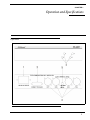
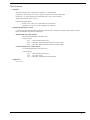
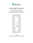
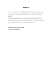
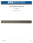
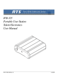
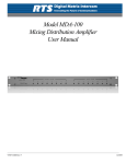
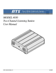
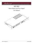
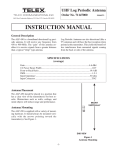
Model PS-4001
Power Supply
User Instructions
9350-7710-000
Rev E 9/2009
PROPRIETARY NOTICE
SHIPPING TO THE MANUFACTURER
The product information and design disclosed herein were originated by
and are the property of Bosch Security Systems, Inc. Bosch reserves all
patent, proprietary design, manufacturing, reproduction, use and sales
rights thereto, and to any article disclosed therein, except to the extent
rights are expressly granted to others.
All shipments of product should be made via UPS Ground, prepaid (you
may request from Factory Service a different shipment method). Any
shipment upgrades will be paid by the customer. The equipment should
be shipped in the original packing carton. If the original carton is not
available, use any suitable container that is rigid and of adequate size. If
a substitute container is used, the equipment should be wrapped in paper
and surrounded with at least four (4) inches of excelsior or similar
shock-absorbing material. All shipments must be sent to the following
address and must include the Proof of Purchase for warranty repair.
Upon completion of any repair the equipment will be returned via
United Parcel Service or specified shipper, collect.
COPYRIGHT NOTICE
Copyright 2009 by Bosch Security Systems, Inc. All rights reserved.
Reproduction, in whole or in part, without prior written permission from
Bosch is prohibited.
WARRANTY NOTICE
Factory Service Department
Bosch Security Systems, Inc.
8601 East Cornhusker Hwy.
Lincoln, NE 68507 U.S.A.
Attn: Service
See the enclosed warranty card for further details.
CUSTOMER SUPPORT
Technical questions should be directed to:
Customer Service Department
Bosch Security Systems, Inc.
12000 Portland Avenue South
Burnsville, MN 55337 USA
Telephone: 1-877-863-4169
Fax: 800-323-0498
FCC STATEMENT
This equipment users, and can radiate radio frequency energy that may
cause interference to radio communications if not installed in accordance with this manual. The equipment has been tested and found to
comply with the limits of a Class A computing device pursuant to Subpart J, Part 15 of FCC Rules which are designed to provide reasonable
protection against such interference when operated in a commercial
environment. Operation of this equipment in a residential area may
cause interference which the user (at his own expense) will be required
to correct.
RETURN SHIPPING INSTRUCTIONS
Customer Service Department
Bosch Security Systems, Inc. (Lincoln, NE)
Telephone: 402-467-5321
Fax: 402-467-3279
Factory Service: 800-553-5992
This product meets Electromagnetic Compatibility Directive 89/336/EEC
Please include a note in the box which supplies the company name,
address, phone number, a person to contact regarding the repair, the type
and quantity of equipment, a description of the problem and the serial
number(s).
This package should include:
QTY
DESCRIPTION
PART NO.
90107710000 (US)
1
PS4001 Final Assembly
or
90107710001 (EU)
THE LIGHTNING
FLASH AND
ARROWHEAD
WITHIN THE TRIANGLE IS A WARNING
SIGN ALERTING
YOU OF “DANGEROUS VOLTAGE”
INSIDE THE PRODUCT.
CAUTION: TO REDUCE THE
RISK OF ELECTRIC SHOCK,
DO NOT REMOVE COVER. NO
USER-SERVICABLE PARTS
INSIDE. REFER SERVICING TO
QUALIFIED SERVICE PERSONNEL.
THE EXCLAMATION POINT
WITHIN THE
TRIANGLE IS A
WARNING SIGN
ALERTING YOU
OF IMPORTANT
INSTRUCTIONS
ACCOMPANYING THE PRODUCT
SEE MARKING ON BOTTOM/BACK OF PRODUCT
WARNING: APPARATUS SHALL NOT BE EXPOSED TO DRIPPING OR
SPLASHING AND NO OBJECTS FILLED WITH LIQUIDS, SUCH AS VASES,
SHALL BE PLACED ON THE APPARATUS.
WARNING: THE MAIN POWER PLUG MUST REMAIN READILY OPERABLE.
CAUTION: TO REDUCE THE RISK OF ELECTRIC SHOCK, GROUNDING OF
THE CENTER PIN OF THIS PLUG MUST BE MAINTAINED.
WARNING: TO REDUCE THE RISK OF FIRE OR ELECTRIC SHOCK, DO NOT
EXPOSE THIS APPRATUS TO RAIN OR MOISTURE.
WARNING: TO PREVENT INJURY, THIS APPARATUS MUST BE SECURELY
ATTACHED TO THE FLOOR/WALL/RACK IN ACCORDANCE WITH THE
INSTALLATION INSTRUCTIONS.
This product is AC only.
1
Power Cord
2504000300
1
User Manual
93507710000
1
Warranty Card
38110-390
1
User Information
38110-668
1
Statement of Conformity
38110-675
1
Int’l Cordsets, European model only
550024000
4
Rubber Feet
56471-001
Important Safety Instructions
1.
Read these instructions.
2.
Keep these instructions.
3.
Heed all warnings.
4.
Follow all instructions.
5.
Do not use this apparatus near water.
6.
Clean only with dry cloth.
7.
Do not block any ventilation openings. Install in accordance with the
manufacturer’s instructions.
8.
Do not install near any heat sources such as radiators, heat registers, stoves,
or other apparatus (including amplifiers) that produce heat.
9.
Do not defeat the safety purpose of the polarized or grounding-type plug. A
polarized plug has two blades with one wider than the other. A grounding
type plug has two blades and a third grounding prong. The wide blade or the
third prong are provided for your safety. If the provided plug does not fit into
your outlet, consult an electrician for replacement of the obsolete outlet.
10.
Protect the power cord from being walked on or pinched particularly at
plugs, convenience receptacles, and the point where they exit from the
apparatus.
11.
Only use attachments/accessories specified by the manufacturer.
12.
Use only with the cart, stand, tripod, bracket, or table specified by the
manufacturer, or sold with the apparatus. When a cart is used, use caution
when moving the cart/apparatus combination to avoid injury from tip-over.
13.
Unplug this apparatus during lightning storms or when unused for long
periods of time.
14.
Refer all servicing to qualified service personnel. Servicing is required when
the apparatus has been damaged in any way, such as power-supply cord or
plug is damaged, liquid has been spilled or objects have fallen into the
apparatus, the apparatus has been exposed to rain or moisture, does not
operate normally, or has been dropped.
CHAPTER 1
Operation and Specifications
Operation
FIGURE 1.
PS-4001 Reference View
3
1.
Universal AC Power Input: The unit accepts any input power in the range opf 100-240 VAC, 50/60 Hz.
2.
Connector to ES-4000A: This connector carries power to the ES-4000A expansion station, and carries the four audio
channels of the ES-4000A. When a Telex ES-4000A is connected to the PS-4001, each of the four channels of audio
is “broken out” to the respective channel connections.
3.
Intercom Channel Connectors: These connectors carry power to the intercom system and provide termination for the
audio signal of each individual intercom channel.
4.
Channel Status Indicators: The indicators are green for normal operation and red when there is an overload or short
circuit. The circuitry in the unit will automatically reset when the overload or shirt circuit is located and fixed, and the
LED will go back to green.
5.
BAL/UNBAL Selector Switch: This selector switch allows the user to configure the unit for use in either an
Audiocoom (BALANCED) or ClearCom (UNBALANCED) system. Compatibility includes channel connector pinouts, channel power requirements, and call signaling requirements. The default setting for this switch is in the
Audiocom (BAL) position.
NOTE:
In order to connect the PS-4001 to a 2-channel ClearCom system using a 6-pin connector, an adaptor cable,
shown in Figure 2, must be constructed.
FIGURE 2.
4
ClearCom Cable Assembly
Specifications
GENERAL
Input Power Requirements: 100 to 240 VAC, 50/60 Hz, 1.0 Amp maximum
Output Power (each channel): 24 ±1 VDC, 1 Amp per channel (not to exceed 3.0 Amp total)
Dimensions: 1.75” (44.5mm) high x 8.25” (209.5mm) wide x 10.31” (261.9 mm) deep
Weight: approxiamately 2.5lb. (1.13 kg)
Environmental Requirements:
Storage: -20°C to 80°C, 0% to 95% humidity, non-condensing
Operating: 0°C to 50°C, 0% to 95% humidity, non-condensing
INTERCOM CHANNELS - General
Connector Type: One XLR-3M audio connector for each channel. Pin-out depends on setting of BAL/UNBAL switch for
balanced or unbalanced operation as defined below:
Balanced Mode (Set to BAL position)
Line Terminating Impedance: 300 Ohms ±10%
Connector Pinout
Pin 1
Pin 2
Pin 3
Common (audio and DC return)
Full-Duplex, balanced intercom audio and +24 VDC output
Full-Duplex, balanced intercom audio and +24 VDC output
Unbalanced Mode (Set to UNBAL position)
Line Terminating Impedance: 200 Ohms ±10%
Connector Pinout
Pin 1
Pin 2
Pin 3
Common (audio and DC return)
+30 ±1 VDC output
Full-Duplex, unbalanced intercom audio high
APPROVALS
UL, CUL, CE
5