1
TELEDYNE
HASTINGS
INSTRUMENTS
INSTRUCTION MANUAL
IGE 3000
ION GAUGE
ISO 9001
C E R T I F I E D
Manual Print History
The print history shown below lists the printing dates of all revisions and addenda created for this
manual. The revision level letter increases alphabetically as the manual undergoes subsequent updates.
Addenda, which are released between revisions, contain important change information that the user should
incorporate immediately into the manual. Addenda are numbered sequentially. When a new revision is
created, all addenda associated with the previous revision of the manual are incorporated into the new
revision of the manual. Each new revision includes a revised copy of this print history page.
Revision A (Document Number 169-032006) ........................................................................ March 2006
Revision B (Document Number 169-082006)..........................................................................August 2006
Revision C (Document Number 169-102007)........................................................................ October 2007
Revision D (Document Number 169-062008) ............................................................................. June 2008
Revision E (Document Number 169-082010) ..........................................................................August 2010
Visit www.teledyne-hi.com for WEEE disposal guidance.
CAUTION
If equipment is not used in the manner specified by this manual,
protection provided by the equipment may be impaired.
Read sections marked with this symbol with care.
DANGER
Paragraphs marked by this symbol in this document, indicates that a
potential hazard to your personal safety exists from a high voltage source.
Hastings Instruments reserves the right to change or modify the design of its equipment without
any obligation to provide notification of change or intent to change.
169-082010_Ion-Gauge-3000
Page 2 of 21
Table of Contents
1.
QUICK START INFORMATION.................................................................................................................................... 5
2.
GENERAL INFORMATION............................................................................................................................................ 6
2.1.
2.2.
2.3.
2.4.
3.
GENERAL INFORMATION ..................................................................................................................................... 6
IGE-3000 MINI BAYARD/ALPERT (B/A) TUBE ............................................................................................................ 6
SPECIFICATIONS........................................................................................................................................................... 6
MATERIALS EXPOSED TO VACUUM .............................................................................................................................. 7
INSTALLATION................................................................................................................................................................ 8
3.1.
3.2.
3.3.
3.4.
3.5.
3.6.
3.7.
3.8.
4.
INSTALLATION........................................................................................................................................................ 8
RECEIVING INSPECTION ............................................................................................................................................... 8
MOUNTING .................................................................................................................................................................. 8
GROUNDING ................................................................................................................................................................. 8
“D” CONNECTOR ELECTRICAL PIN OUTS ..................................................................................................................... 9
B/A TUBE INSTALLATION ............................................................................................................................................ 9
MOUNTING B/A TUBE TO IGE-3000 ELECTRONICS MODULE ...................................................................................... 9
ENVIRONMENTAL: ....................................................................................................................................................... 9
OPERATION .................................................................................................................................................................... 10
4.1.
4.2.
4.3.
4.4.
OPERATION ................................................................................................................................................................ 10
FRONT PANEL OVERVIEW .......................................................................................................................................... 10
OPERATING MODES ................................................................................................................................................... 11
REMOTE FILAMENT CONTROL.......................................................................................................................... 12
5.
THEORY OF OPERATION ........................................................................................................................................... 14
6.
SET UP GUIDE ................................................................................................................................................................ 15
6.1.
6.2.
6.3.
6.4.
6.5.
6.6.
6.7.
7.
ADVANCE SETUP GUIDE ..................................................................................................................................... 15
RS485 ADDRESS ........................................................................................................................................................ 15
BAUD RATE ............................................................................................................................................................... 15
DATA BITS/PARITY BITS/STOP BITS .......................................................................................................................... 16
TURNAROUND DELAY ................................................................................................................................................ 16
SAVE EEPROM......................................................................................................................................................... 16
RESTORE EEPROM ................................................................................................................................................... 16
RS 232/RS 485................................................................................................................................................................... 17
7.1.
8.
RS232/RS485............................................................................................................................................................ 17
DEVICE STATUS ............................................................................................................................................................ 18
8.1.
8.2.
8.3.
8.4.
9.
ION GAUGE DEVICE STATUS: 4-DIGIT OCTAL WORD................................................................................... 18
COMMAND SYNTAX ................................................................................................................................................... 18
INTERROGATION COMMANDS .................................................................................................................................... 19
PARAMETER MODIFICATION COMMANDS .................................................................................................................. 19
WARRANTY .................................................................................................................................................................... 20
9.1.
9.2.
10.
WARRANTY REPAIR POLICY ...................................................................................................................................... 20
NON-WARRANTY REPAIR POLICY ............................................................................................................................. 20
DRAWINGS & SCHEMATICS ................................................................................................................................. 21
169-082010_Ion-Gauge-3000
Page 3 of 21
DANGER HIGH VOLTAGE
High voltages capable of causing injury or death are present within the IGE 3000 Avoid touching the
connector sockets, tube pins and all internal circuitry within the IGE 3000. SERVICE MUST ONLY BE
PERFORMED BY QUALIFIED TELEDYNE INSTRUMENTS PERSONNEL.
DANGER
Do not turn on the IGE 3000 if there is any danger of explosion from explosive or combustible gasses or gas
mixtures. Ionization gauge tube filaments operate at a temperature sufficiently high enough to be considered an
ignition source.
DANGER
Safe operation of ion producing equipment, including the IGE 3000, requires grounding of its power supply
and the vacuum chamber. LETHAL VOLTAGES may be established under some operating conditions unless
grounding is provided.
DANGER
Ion producing equipment such as the IGE 3000, from any manufacturer, may, under some conditions
provide sufficient conduction via plasma to couple a high voltage electrode to the vacuum chamber. If
conductive parts of the chamber are not grounded, they may attain a potential near that of the high voltage
electrodes during this coupling. Potentially fatal electrical shock could then occur because of the high voltage
between these vacuum chamber parts and ground. Grounding, though simple, is imperative! Ensure that the
ground circuits are correctly utilized, both on your IGE 3000 power supplies and your vacuum chambers,
regardless of the manufacturer, for this phenomenon is not peculiar to the IGE 3000.
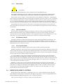
CAUTION
Ensure that BA tube filaments are not turned on unless vacuum IS LESS THAN 10-2 Torr.
TURNING ON filaments at atmosphere MAY result in damage to the BA tube.
CAUTION
Before initiating Degas, vacuum must be 10-7 Torr or less.
Performing Degas at Higher Pressures Could Damage the B/A Tube
169-082010_Ion-Gauge-3000
Page 4 of 21
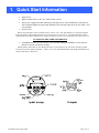
1. Quick Start Information
•
Apply Power
•
Apply 24 VDC Power to the “D” connector Pin 3 and 4.
•
After power is applied the IGE 3000 will go through self test, CPU initialization, and LED test.
(The individual LEDs will sequentially illuminate then the IGE 3000 enters the “No Mode” and
is operational).
•
Operate Tube
Before operating tube, ensure vacuum is below 1x10⁻² Torr. The IGE 3000 has an automatic shutoff
feature that will not allow filament turn on at pressures above 1x10⁻² Torr. The shutoff feature will also
automatically turn off the filament if it is turned on (below 1x10⁻² Torr) and pressure rises above 1x10⁻²
TO TURN ON THE TUBE’S FILAMENTS:
•
“DOUBLE CLICK” the select button. (note: Double clicking the SELECT button while the
filament is already On will turn it OFF).
Initially dashes will remain on the display. However, as the tube heats up and starts operating, within
seconds the pressure will be displayed. LED’s (F1 or F2) will be illuminated, indicating which filament is
selected and that it is turned on.
High Low
Emis
DGas
F1
SP
K
F2
Fil
2X=On/Off
169-082010_Ion-Gauge-3000
Page 5 of 21
2. General Information
2.1.
GENERAL INFORMATION
The Teledyne Hastings Instruments IGE-3000 is a small, fully self contained ion gauge electronics
module. The mini- Bayard Alpert style ion gauge tube is attached to the electronics module by a 12 pin
circular connector. The IGE-3000 is designed for quick, easy installation and will provide the user with
long lasting, trouble free, reliable vacuum measurement.
2.2.
IGE-3000 Mini Bayard/Alpert (B/A) Tube
The IGE-3000 mini B/A tube is all metal construction, with the primary enclosure fabricated of 304
stainless steel. It is UHV compatible and utilizes a fine wire collector located in the center of the grid. The
duel Yttria coated filaments are individually supported to provide uniform output over variations in
temperature and normal ageing. The typical user should experience a filament lifetime of approximately
10,000 hours. Its physical size is much smaller than the traditional glass type B/A tube. Since there is no
glass envelope, the traditional safety concerns associated with glass type B/A tubes is eliminated.
2.3.
Specifications.
Pressure Range ........................................................................................................1x10-2 to 1x10⁻¹⁰ Torr
*Accuracy ................................................................±15% of reading for the range 1x10⁻² to 1x10⁻⁸ Torr
Degas .......................................................................................................................................... 5W e-beam
Emission Current ....................................................................................................0.01, 0.1, 1 mA, or Auto
Filament Bias Potential ............................................................................................................ +30 V ±0.3%
Grid Potential ........................................................................................................................ +180 V ±0.3%
Operating Temperature ..................................................................................................................... 0-50°C
Digital Communications .............................................................................................................. RS232/485
Connector ................................................................................................................. 15-pin subminiature D
Bake out Temperature ................................................................................ 200°C with electronics removed
** Electrical Noise Immunity........................................ENC 61010 Class A and IEC 61326-1: Section 6.2
Input Voltage Operating Range ................................................................................. 11.5 VDC to 30 VDC
Input Power.......... ........................................................................24 VDC @ 350 mA (Normal Operation)
.............................................................................................................24 VDC @ 850 mA (During Degas)
Power/Interface Connector ............................................................................................ 15 pin subminiature
Process Control.................................................................................. 2 independent TTL set point outputs
Weight......................................................................................................................................1.5 lbs. (max)
Transducer Mounting................................................................................................................Any position
Remote Control Capable ...............................................................................................................................
Automatic High Pressure Cut off ..................................................................................................................
*Accuracy specification is with the B/A tube originally shipped with the IGE 3000. The
IGE 3000 is calibrated with and matched to the B/A tube at the factory. Changing or swapping the B/A
tube with a B/A tube one other than the one originally shipped with the unit may effect the calibration.
**Complies with IEC 61010-1 (Safety requirements for measurement, control, and laboratory use).
169-082010_Ion-Gauge-3000
Page 6 of 21
2.4.
Materials exposed to Vacuum
•
Yttia coated Iridium
•
Nickel
•
304 Stainless Steel
•
Glass
•
Tungsten
•
Platinum Clad Molybdenum
169-082010_Ion-Gauge-3000
Page 7 of 21
3. Installation
3.1.
INSTALLATION
3.2.
Receiving Inspection
Your instrument has been manufactured, calibrated and carefully packed so that upon receiving your
order it is ready for operation. However, when you unpack, please inspect all items for any obvious signs of
damage due to shipment. Immediately advise Teledyne Hastings and the carrier if any damage is
suspected.
Use the packing slip as a check list and insure all parts are present including any optional equipment and
that the options are correct (i.e. output, range, gas, pin out)
If a return is necessary, obtain an RMA (Return Material Authorization) number from our Customer
Service Department at 1-800-950-2468.
3.3.
Mounting
The IGE-3000 is an “indoor use only” instrument. The IGE-3000 can be mounted in any attitude or
position. Reasonable care should be taken to install the IGE-3000 where it will be protected from physical
damage. To facilitate ease of reading the LED readout, the connector “keyway” of the B/A tube should be
mounted at the 3 o-clock position.
3.4.
Grounding
For safety reasons the case of the IGE-3000 must be grounded to the vacuum chamber.
This is normally accomplished mechanically through the vacuum chamber base flange via the
B/A tube physical connection. The electronics module is grounded through a pin in the
connector plug once the IGE-3000 module is plugged into the B/A tube. To ensure the best grounding
possible, ensure that the tube to base set screw is fully tightened once the IGE-3000 is installed.
DANGER
Ion producing equipment such as the IGE-3000, from any manufacturer, may, under some conditions provide
sufficient conduction via plasma to couple a high voltage electrode to the vacuum chamber. If conductive parts of the
chamber are not grounded, they may attain a potential near that of the high voltage electrodes during this coupling.
Potentially fatal electrical shock could then occur because of the high voltage between these vacuum chamber parts
and ground. Grounding, though simple, is imperative! Ensure that the ground circuits are correctly utilized, both on
your IGE-3000 power supplies and your vacuum chambers, regardless of the manufacturer, for this phenomenon is
not peculiar to the IGE-3000.
169-082010_Ion-Gauge-3000
Page 8 of 21
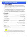
3.5.
“D” Connector Electrical Pin outs
The figure below indicates all pin outs.
FIGURE 1- IGE-3000 “D” CONNECTOR
NOTE: Set Point High, Set Point Low and Remote
Start, use Digital ground Pin 8 as signal return path.
3.6.
B/A Tube Installation
The Bayard/Alpert (B/A) tube may be installed in any orientation. Although the transducer tube is
rugged and will perform well in many harsh environments, the tube should be installed in a clean and
careful manner. The B/A tube is configured with the vacuum fitting requested.
CAUTION
The electronics unit is calibrated when married to the B/A tube. Avoid interchanging B/A
tubes with different electronics modules since this may affect accuracy and will void calibration.
3.7.
Mounting B/A tube to IGE-3000 Electronics Module
The B/A tube plugs into the IGE-3000 via the 12 pin circular connector located inside the lower base
housing of the IGE-3000 electronics module. The B/A tube is keyed to ensure proper connections. Slightly
rotate the electronics unit until the keyway of the connector aligns with the key on the B/A tube, and then
snugly plug the electronics module to the B/A tube. Tighten the set screw located on the base housing to
the B/A tube. The set screw secures the tube to the electronics module and also ensures proper grounding
of the B/A tube to the IGE-3000 base housing.
3.8.
Environmental:
Indoor use
Operating temperature range from 0° to 40° C
Maximum relative humidity: 80% for temperatures up to 31° C decreasing linearly to 50% Relative humidity at
40° C.
169-082010_Ion-Gauge-3000
Page 9 of 21
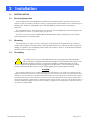
4. Operation
4.1.
Operation
4.1.1.
Apply Power
Apply 24 VDC Power to the “D” connector pin 3 and 4. (Refer to Section 2.5 /Figure 1, for the “D”
connector pin out information).
After power is applied the IGE-3000 will go through self test, CPU initialization, and LED test. (The
individual LED’s will sequentially illuminate then the IGE-3000 enters the “No Mode” and is operational).
4.1.2.
Operate Tube
Before operating tube, ensure vacuum is below 1x10⁻² Torr. The IGE-3000 has an automatic
shut-off feature that will not allow filament turn on at pressures above 1x10⁻² Torr. The shutoff feature will also automatically turn off the filament if it is turned on (below 1x10⁻² Torr)
and pressure rises above 1x10⁻²
To turn on the tube’s filaments:
“DOUBLE CLICK” the select button. (Note: Double clicking the SELECT button while the filament is
already On will turn it OFF).
Initially dashes will remain on the display. However, as the tube heats up and starts operating, within
seconds the pressure will be displayed. LED’s (F1 or F2) will be illuminated, indicating which filament is
selected and that it is turned on.
NOTE: Although rare, difficulties turning on the filament can be experienced if the B/A tube is new or has been
turned off for an extended period of time and the monitored vacuum chamber’s base pressure is too close to the upper
pressure limit of 1X10⁻². Filament turn on difficulties are usually related to the time it takes for the filament to
initially “turn on” (heat up), cause electron emissions and for the IGE-3000 to properly sense B/A tube output
(pressure).
As a safety feature and to prevent damage to the B/A tube, the IGE-3000 is designed to shut off the filament if
“in range” pressure is not sensed within a pre-programmed period of time. The start up time for a new tube or one
that has been off for extended periods of time could be beyond these programmed time limits when operating in the
higher base pressure ranges. If the filament does prematurely shut off during initial operation or after being turned
off for an extended period, simply change the Emission setting to the 0.01 mA range (refer to Section 3.3.2) and then
turn on filament again. Once the filament is on, and the IGE-3000 is indicating pressure, the emission setting can
then be changed to the desired setting. After the B/A tube’s filament has been in operation for a short period of time,
any filament start up difficulties should disappear.
4.2.
Front Panel Overview
High Low
Emis
DGas
F1
SP
K
F2
Fil
2X=On/Off
169-082010_Ion-Gauge-3000
Page 10 of 21
4.2.1.
SELECT
SELECT is a push-button. Pressing it will scroll through the different available operating modes. Rapidly
“double clicking” SELECT will either turn the selected filament on (if unit is off) or off (if the unit is on)
Note: Ensure vacuum is below 1x10⁻² Torr. The IGE-3000 has an automatic shutoff feature that will not allow
filament turn on at pressures above 1x10⁻² Torr. The shutoff feature will also automatically turn off the filament if
it is on (below 1x10⁻² Torr) and pressure rises above 1x10⁻².
4.2.2.
ADJUST
ADJUST is a rotary encoder. Rotating ADJUST will select desired parameters within the different
modes.
4.2.3.
STATUS BAR (RED LED’s)
The status bar displays information about the condition of the IGE-3000. A particular LED, when lit,
indicates that particular condition has been met.
High and Low will illuminate when respective TTL set point is activated high (+5 VDC).
F1 and F2 illuminate when the respective filaments are turned on.
The error LED is located in the middle of the top row and is not labeled. It is illuminated if the filament is not
turned on or the filament is turned on and indicated pressure is out of range.
4.2.4.
MODE BAR (GREEN LED’s)
The Mode bar indicates in which mode the IGE-3000 is currently operating.
A particular LED, when lit indicates that particular mode has been entered.
The Available modes are Emis (emission), Dgas, Sp (set point), K (K factor) and Fil filament).
Refer to Section 3.3 for detailed explanations of the modes.
4.3.
Operating Modes
4.3.1.
No Mode (Normal Mode):
NO MODE is the default (normal) operating mode of the IGE-3000. During NO
MODE the numeric display indicates BA tube out put (pressure measurement value). Dashes displayed
on the numeric display indicate that the filament is not turned on, not operating properly, or that the
readings are out of range. The filament will automatically turn off if indicated pressure is above 1x10 -2. NO
MODE is automatically entered when there are no modes selected or the current selected mode has timed
out. Time out occurs if no operator action is initiated after 15 seconds.
NOTE: Dashes displayed on the numeric display with the Filament 1 or Filament 2 LED’s illuminated, is an
indication that the B/A tube is not operating properly.
4.3.2.
Emis (emission) Mode:
The Emis mode is entered by scrolling to the Emis position by pressing the SELECT push button. The
desired B/A tube emission current is then selected by rotating the ADJUST encoder to the desired emission
range. Available settings are 0.01 mA, 0.1 mA, 1 mA or AUTO ranging. In most situations the optimum
setting for the IGE-3000 is AUTO ranging. In AUTO ranging the IGE-3000’s CPU automatically
determines and sets the optimum emission current range as determined by the CPU and is based on the
pressure measurement. When operating in other than AUTO ranging, the following settings are
recommended: for the pressure ranges above 1x10⁻⁴ Torr use 0.01 mA; for the pressure ranges 1x10⁻⁴ to
1x10⁻⁵ Torr use 0.1 mA and for the pressures below 1x10⁻⁵ Torr use 1 mA.
169-082010_Ion-Gauge-3000
Page 11 of 21
4.3.3.
DGas Mode:
CAUTION:
BEFORE INITIATING DEGAS, VACUUM MUST BE AT OR BELOW 1x10⁻⁷
EXCESSIVE DEGASSING AT ANY TIME CAN DISTORT THE GAUGE ELECTRODES AND
CAN RESULT IN A MISLEADING TRANSIENT DECREASE IN PRESSURE INDICATION
Degas mode is used to “Degas” or clean the inside areas of the BA tube of impurities. Degassing the
tube can improve readings and accuracy. Degassing is not effective at pressures above 1x 10⁻⁷. Degassing is
only recommended if the gauge is heavily contaminated or after exposure to surface active gasses such as
O2. As is typical of all B/A type gauges, pressure readings will be unstable for a several hours until the
chemical composition and absorbed layers on the newly cleaned surfaces in the BA tube reach equilibrium.
During Degas the emission current is increased to 10 mA and the grid voltage is raised to 500 VDC.
This action causes the temperature of the grid to be raised sufficiently enough to burn off most unwanted
contaminants.
4.3.4.
(K-factor) Mode:
K factor mode is entered by scrolling to the K-factor position by slowly pressing the SELECT push
button. The K-factor can be set by turning the ADJUST encoder to the desired setting. The default
(normal) K factor for the IGE-3000 B/A tube is 10. If required the K factor can be adjusted from 1 to 99.
The K factor is associated with tube sensitivity and is a function of the physical tube design.
4.3.5.
Fil (filament) Mode:
Fil mode is entered by scrolling to the Fil position by slowly pressing the SELECT push button. The
desired filament is then selected once in the Fil mode by turning the ADJUST encoder to the desired
setting. The IGE-3000 incorporates two separate identical filaments to dramatically increase B/A tube life.
Either filament can be selected at any time.
4.3.6.
SP (set point) Mode:
SP mode is entered by scrolling to the SP position (HI or LOW) by slowly pressing the
SELECT push button. The set point values can then be selected by turning the ADJUST encoder to the
desired setting. SP alarms are indicated by the HIGH/ LOW LED’s on the status bar. In addition the IGE3000 has two corresponding TTL outputs (HI and LOW) for process control. These outputs are available
via the 15-pin connector. (Refer to Section 2.4/Figure 1).
To view the High set point, place the IGE-3000 in the High mode by slowly pressing the SELECT
button until the SP led and High led are flashing. The display then indicates the high set point value. To
change set point values rotate ADJUST CW to increase or CCW to decrease. There is no hysteresis (dead
band). During normal operation the alarm light will trigger and the TTL output (pin # 1) will go high
(+5V) if the pressure exceeds the set point.
Similarly, to view the Low set point, place the IGE-3000 in the Low mode by slowly pressing the
SELECT button again until the Low led and the SP led are flashing. The display then shows the low set
point value. To change set point values rotate ADJUST CW to increase or CCW to decrease. During
normal operation the alarm light will trigger and the TTL output (pin # 2) will go high (+5V) if the
pressure becomes less than the set point.
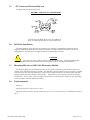
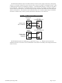
4.4.
REMOTE FILAMENT CONTROL
Broad range pressure monitoring (i.e. atmosphere to 1X 10⁻¹⁰) can be realized when using the IGE3000’s Remote Control feature in conjunction with higher range gauges such as the Hastings HPM 2002,
Hastings HPM 2002 OBE, Hastings DV-6 CVT or similar instruments.
(Refer to Section 2.4/Figure 1 and Figure 3 below for wiring information).
169-082010_Ion-Gauge-3000
Page 12 of 21
The IGE-3000’s filament may be controlled remotely via the D power supply connector by wiring relay
contacts or a transistor switch across pins 8 and 9, (refer to section 2.5 /Figure 1 and Figure 3 below). Pin 8
is digital ground and pin 9 is the filament control line. The IGE filament will turn on when pin 9 is pulled
low or grounded. This may be accomplished either by relay contacts or by utilizing a transistor switch. A
contact closure connected across “D” connector pin 8 and pin 9 must be such that it closes when the IGE3000 is to be turned on. The transistor circuit connected across “D” connector pin 8 and pin 9 should be
such that it conducts and provides a ground path when the IGE-3000 is to be turned on.
FIGURE 3- REMOTE FILAMENT CONTROL
CONTROLLING
VACUUM
GAUGE
IGE 3000
"D" POWER CONNECTOR
PIN 9
K1
REMOTE START
RELAY INTERFACE
K
PIN 8
CONTROLLING
VACUUM
GAUGE
IGE 3000
"D" POWER CONNECTOR
PIN 9
REMOTE START
TRANSISTOR
INTERFACE
Q1
PIN 8
NOTE: Manual operation is unaffected by using remote control. (i.e. Filament can be turned off
manually if turned on via remote control and filament can be turned on manually, after being turned off via
remote control).
169-082010_Ion-Gauge-3000
Page 13 of 21
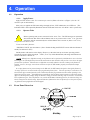
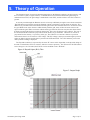
5. Theory of Operation
The functional parts of a typical ionization gauge tube are the filament (cathode), the grid (anode), and
the ion collector (refer to Figure 4 below). The IGE-3000 control circuit maintains the grid voltage is
maintained at 30 VDC, the grid voltage is maintained at 180 VDC, and the collector is 0 VDC relative to
ground.
A current passed through the filament causes it to heat up sufficiently enough to cause electron emission.
The IGE 3000 control circuit controls the filament current to maintain a constant electron emission. The
difference of potential between the filament and the grid causes these emitted electrons to accelerate toward
the grid. While most of the electrons collide directly with the grid, many of these electrons traverse the
region inside the grid. When an electron collides with a gas molecule, electrons may become disassociated
from the gas molecules leaving a positively charged ion. These ions accelerate to the collector. The rate of
the electron/molecule collisions is proportional to the density of gas molecules. Therefore ion current is
proportional to the density (i.e. pressure) of the gas. The collector’s ion current is fed into a precision
electrometer where it is converted to a DC voltage. This DC voltage is then processed through a precision
analog to digital converter and the data is passed to the IGE-3000 CPU. The CPU will then process this
data a pressure reading is displayed.
The B/A tube sensitivity is expressed by the term “K” factor and is dependant on the physical design of
the tube. The definition of K=ion current/ (emission current x pressure). The K factor for the IGE-3000 is
10 for nitrogen or air. If needed, the K factor can be modified via the “K Mode”.
Figure 4- Bayard Alpert (B/A) Tube
Figure 5- Output Graph
169-082010_Ion-Gauge-3000
Page 14 of 21
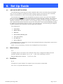
6. Set Up Guide
6.1.
ADVANCE SETUP GUIDE
The IGE-3000 has several setup and control commands which can be accessed by using the ADJUST
rotary encoder and SELECT push-button while viewing the display. Note that most of the commands,
which are described below, can be accessed using equivalent RS232/485 Commands.
The advanced setup is accessed from NO MODE, the default run mode. Each click of the ADJUST
rotary encoder in the clockwise direction will advance the display through each command. Once arriving at
the desired command, the user can change the parameter (or initiate command) by slowly pressing the
SELECT push-button. If the user wishes to save any changes simply go to the “Save EE prom” mode press
select. When finished with the advanced setup, the user may return to the normal NO MODE by turning
the ADJUST counterclockwise until the pressure is once again displayed. Note that turning the ADJUST
clockwise indefinitely will continuously cycle through all the commands.
The commands are:
•
Normal Run
•
RS485 Address
•
Baud Rate
•
Data bits/Parity Bits/Stop Bits
•
Turn Around Delay
•
Save EE Prom
•
Restore EE Prom
The following list gives a description of each of the commands listed above along with the syntax for the
equivalent RS232/485 command.
NOTE: To access the following commands, rotate the ADJUST pot Counterclockwise.
6.2.
RS485 Address
A_01
The RS485 address is the address of the IGE-3000. If the unit is configured for RS232, then this
parameter should not be adjusted. A_01, A_02, … A_FE, A_FF (Valid range 01 to DF)
Equivalent RS232/485 command.
6.3.
*{aa}A={aa}<CR>
Baud Rate
B_9.6
The baud rate is given in kbaud. For example, B_9.6 corresponds to a 9600 baud.
Note: There is no equivalent RS232/485 command.
169-082010_Ion-Gauge-3000
Page 15 of 21
6.4.
Data Bits/Parity Bits/Stop Bits
P8n1
The first character, “8” corresponds to the number of data bits. (e.g. 7 or 8).
Second character, “n” corresponds to the parity bit. (i.e. n- no parity, E- even parity, o- odd parity, 0space, 1- mark)
The last character, “1” corresponds to the number of stop bits. (e.g. 1 or 2)
8n1, 8n2, 7n2, 7E1, 7E2, 7o1, 7o2, 701, 702, 711,712
Note: There is no equivalent RS232/485 command.
6.5.
Turnaround Delay
dt06
dt00, dt01, ...dtFE, dtFF
The turnaround delay is unique to multipoint communications. It is the delay between receipt of an
incoming command to transmission of the response. Each increase in the hex value corresponds to an
increase in the delay time of approximately 8 ms.
Note: Equivalent RS232/485 command.
6.6.
*{aa}T={dd}<CR>
Save EEPROM
S_EE
EEW<CR>
This command stores setting data to EPROM memory.
Note: There is no equivalent RS232/485 command
6.7.
Restore EEPROM
r_EE
EER<CR>
Note: There is no equivalent RS232/485 command
169-082010_Ion-Gauge-3000
Page 16 of 21
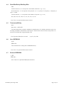
7. RS 232/RS 485
7.1.
RS232/RS485
The IGE-3000 is designed to communicate with external devices by either RS232 or RS485 via the two
RJ-11 connectors. Refer to section 3.2 Figure 2 for connector locations. RS232 via the left connector on
and the RS485 is via either connector. Software capable of communicating with the IGE-3000 is available
upon request.
Refer to Figure 7 below for pin out and wiring information.
7.1.1.
Wiring for IGE-3000 RS232/485
7.1.2.
Wiring for RS232/485
RS 485 half duplex
RS 485 full duplex
Pin #1
T+/R+
Pin #1
T+
Pin #2
T-/R-
Pin #2
T-
Pin #3
GND
Pin #3
GND
Pin #4
GND
Pin #4
GND
Pin #5
n/a
Pin #5
R-
Pin #6
n/a
Pin #6
R+
169-082010_Ion-Gauge-3000
Page 17 of 21
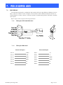
8. Device Status
8.1.
ION GAUGE DEVICE STATUS: 4-DIGIT OCTAL WORD
When requested to transmit its status the IGE-3000 responds with a 4-digit octal word.
FIGURE 7 -1 – DIGIT OCTAL WORD
•
•
•
bit 11: Serial Receiver Overload
bit 10: Main Board EEPROM Error.
bit 9: Communication Syntax Error.
•
•
•
bit 7 Emission Setting.
bit 8 Emission Setting.
bit 6: Filament Selection. (0=filament 1, 1=filament 2)
FIGURE 8- BITS 7 & 8 EMISSION CODE
8.2.
BITS 7 & 8
BIT 8
BIT 7
NO EMISSIONS
0.01 Ma
0.1 mA
0
0
1
0
1
0
1.0 mA
1
1
•
•
•
bit 5: Filament Status. (0=non-operating, 1=operating)
bit 4: Degas (0=degas off, 1=degas on)
bit 3: Pressure less than (0.1e-9 Torr) Set if true.
•
•
•
bit 2: Pressure Greater than (1.0e-3 Torr) set if true.
bit 1: High Set point Alarm Set if pressure is greater than the high set point
bit 0: Low Set point Alarm Set if pressure is less than the low set point
Command Syntax
In the following examples of syntax codes, the special characters are explained:
•
The characters in square brackets [ ] represents a command string, either upper or lower case
command characters accepted. All characters must follow each other in the string with no spaces
or other characters.
•
The characters within wavy brackets { } contain choices for the appropriate command.
•
The characters within the symbols < > are the common abbreviations for the one digit ASCII
control codes which they represent, (e.g. <CR> represents carriage return).
169-082010_Ion-Gauge-3000
Page 18 of 21
•
When entering more than one command in the same data string, they must be separated by a
comma.
•
All command strings must be followed by the terminator character (carriage return <CR>, also
known as ENTER).
•
When a lower case character is present in an example it represents an option.
•
Character Description Valid Inputs:
a RS-485 Address (hexadecimal 0-9, A-F) 01 - DF
m Most Significant Digit Of Mantissa 1 - 9
d Decimal Digit 0 - 9
e Exponent 0 - 5
u Unit Of Pressure T, M, or P
, Command Separator (comma) N/A
<CR> Command Terminator (carriage return) N/A
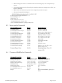
8.3.
8.4.
Interrogation Commands
Command Description
Format
Sample Response
Transmit K Factor
Transmit Electrometer Output
Transmit Fil Status
Transmit Averaged Pressure
Transmit RS-485 Address
Transmit High Set point
Transmit Low Set point
Transmit Device Status
Transmit Turnaround Delay
Transmit Selected Units
Transmit Software Version #
Transmit Filament F<CR>
Transmit Emission Setting
K<CR>
W<CR>
F<CR>
P<CR>
A<CR>
H<CR>
L<CR>
S<CR>
T<CR>
U<CR>
V<CR>
f1<CR>
I<CR>
K Factor: 1.0000+01
V1 Ave: 1.2765e+00
Filament #1 on High Voltage on
Pa: 1.23456e+0 Torr<CR>
Multidrop Address: 01<CR>
Hi: 1.00000e+1 Torr<CR>
Lo: 1.00000e-2 Torr<CR>
00044<CR>
Comm Delay: 6<CR>
Torr<CR>
IGE-3000 Vxxxx
Transmit Degas Time
D<CR>
Remaining Degas Time: 54
minutes<CR>
Emission: 0.01 mA<CR> (note:
Filament must be on)
Parameter Modification Commands
Command Description
Format
Sample Response
Modify High Setpoint
Modify Low Setpoint
Modify RS-485 Address
Modify Turnaround Delay
Modify Emission
Modify Degas Time
Turn Gauge/Filament on F1 or F2
Turn Gauge/Filament off
Escape
H={m.dd}E{+e}<CR>
L={m.dd}E{-e}<CR>
*{aa}A={aa}<CR>
*{aa}T={dd}<CR>
E={m.d}E{-e}<CR>
R={dd}<CR>
F1<CR>
F0<CR>
<Esc>
1.00000e-9 to 9.99999e+9
1.00000e-9 to 9.99999e+9
1 To DF (Hexadecimal)
0 To 255 (Decimal)
* must be exact
0 To 5 (Decimal)
NA
NA
Reset Command Buffer (ignore prior
Input)
169-082010_Ion-Gauge-3000
Page 19 of 21
9. WARRANTY
9.1.
Warranty Repair Policy
Hastings Instruments warrants this product for a period of one year from the date of shipment to be free
from defects in material and workmanship. This warranty does not apply to defects or failures resulting
from unauthorized modification, misuse or mishandling of the product. This warranty does not apply to
batteries or other expendable parts, or to damage caused by leaking batteries or any similar occurrence. This
warranty does not apply to any instrument which has had a tamper seal removed or broken.
This warranty is in lieu of all other warranties, expressed or implied, including any implied warranty as to
fitness for a particular use. Hastings Instruments shall not be liable for any indirect or consequential
damages.
Hastings Instruments, will, at its option, repair, replace or refund the selling price of the product if
Hastings Instruments determines, in good faith, that it is defective in materials or workmanship during the
warranty period. Defective instruments should be returned to Hastings Instruments, shipment prepaid,
together with a written statement of the problem and a Return Material Authorization (RMA) number.
Please consult the factory for your RMA number before returning any product for repair. Collect freight
will not be accepted.
9.2.
Non-Warranty Repair Policy
Any product returned for a non-warranty repair must be accompanied by a purchase order, RMA form
and a written description of the problem with the instrument. If the repair cost is higher, you will be
contacted for authorization before we proceed with any repairs. If you then choose not to have the product
repaired, a minimum will be charged to cover the processing and inspection. Please consult the factory for
your RMA number before returning any product repair.
TELEDYNE HASTINGS INSTRUMENTS
804 NEWCOMBE AVENUE
HAMPTON, VIRGINIA 23669 U.S.A.
ATTENTION: REPAIR DEPARTMENT
TELEPHONE
TOLL FREE
FAX
E MAIL
INTERNET ADDRESS
(757) 723-6531
1-800-950-2468
(757) 723-3925
[email protected]
http://www.teledyne-hi.com
Repair Forms may be obtained from the “Information Request” section of the Hastings Instruments web
site.
169-082010_Ion-Gauge-3000
Page 20 of 21
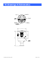
10. Drawings & Schematics
High Low
Emis
DGas
F1
SP
K
F2
Fil
2X=On/Off
HASTINGS
169-082010_Ion-Gauge-3000
Page 21 of 21