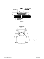
1
TELEDYNE
HASTINGS
INSTRUMENTS
INSTRUCTION MANUAL
HPM-2002-OBE
VACUUM GAUGE
ISO 9001
C E R T I F I E D
Manual Print History
The print history shown below lists the printing dates of all revisions and addenda created for this manual.
The revision level letter increases alphabetically as the manual undergoes subsequent updates. Addenda, which
are released between revisions, contain important change information that the user should incorporate
immediately into the manual. Addenda are numbered sequentially. When a new revision is created, all addenda
associated with the previous revision of the manual are incorporated into the new revision of the manual. Each
new revision includes a revised copy of this print history page.
Revision D (Document Number 155-022002) ......................................................................... February 2002
Revision E (Document Number 155-072002) ...................................................................................July 2002
Revision F (Document Number 155-082002) ............................................................................. August 2002
Revision G (Document Number 155-062004) .................................................................................June 2004
Revision H (Document Number 155-082005) ............................................................................ August 2005
Revision J (Document Number 155-092007) ........................................................................ September 2007
Revision K (Document Number 155-062008)..................................................................................June 2008
Revision L (Document Number 155-112008) ........................................................................ November 2008
Revision M (Document Number 155-122008) ...................................................................... December 2008
Revision N (Document Number 155-082010) ............................................................................ August 2010
Revision P (Document Number 155-102011) ............................................................................ October 2011
Visit www.teledyne-hi.com for WEEE disposal guidance.
CAUTION:
The instruments described in this manual are available with multiple pin-outs.
Ensure that all electrical connections are correct.
CAUTION: The instruments described in this manual are designed for INDOOR use only.
CAUTION:
The instruments described in this manual are designed for Class 2 installations
in accordance with IPC standards
Hastings Instruments reserves the right to change or modify the design of its equipment without
any obligation to provide notification of change or intent to change.
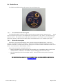
HPM-2002-OBEVacuum Gauge
Page 2 of 39
Table of Contents
1. GENERAL INFORMATION............................................................................................................................................ 5
1.1.
1.2.
1.3.
1.4.
1.5.
1.6.
1.7.
2.
INSTALLATION .......................................................................................................................................................... 7
2.1.
2.2.
2.3.
2.4.
2.5.
3.
FEATURES: ............................................................................................................................................................. 5
MODEL 2002 SENSORS ........................................................................................................................................... 5
HPM-2002-OBE ANALOG OUTPUT MODULE ........................................................................................................ 5
HPM-2002-OBE ANALOG OUTPUT (4-20MA) MODULE ....................................................................................... 5
HPM-2002-OBE RS232/485 OUTPUT MODULE .................................................................................................... 6
HPM-2002-OBE DEVICENET MODULE ................................................................................................................. 6
SPECIFICATIONS ..................................................................................................................................................... 6
RECEIVING INSPECTION ......................................................................................................................................... 7
QUICK START ......................................................................................................................................................... 7
TRANSDUCER INSTALLATION ................................................................................................................................. 7
OBE MODULE INSTALLATION ............................................................................................................................... 7
INITIAL OPERATION ............................................................................................................................................... 8
OPERATING INFORMATION.................................................................................................................................. 9
3.1.
ANALOG OUTPUT (0-10V) ..................................................................................................................................... 9
3.1.1. Overall Functional Description........................................................................................................................ 9
3.1.2. High and Low Set Point Modes ........................................................................................................................ 9
3.1.3. Run Mode ....................................................................................................................................................... 10
3.1.4. Cal Mode ........................................................................................................................................................ 10
3.1.5. GAS Mode....................................................................................................................................................... 11
3.1.6. Analog Output (0-10V) ................................................................................................................................... 11
3.2.
ANALOG OUTPUT (4-20MA) ................................................................................................................................ 13
3.2.1. Overall Functional Description...................................................................................................................... 13
3.2.2. High and Low Set Point Modes ...................................................................................................................... 13
3.2.3. Run Mode ....................................................................................................................................................... 13
3.2.4. Cal Mode ........................................................................................................................................................ 14
3.2.5. GAS Mode....................................................................................................................................................... 15
3.2.6. Analog Output (4-20mA) ................................................................................................................................ 15
3.3.
RS232/485 WITH DISPLAY .................................................................................................................................. 17
3.3.1. Overall Functional Description...................................................................................................................... 17
3.3.2. COMMAND SYNTAX ..................................................................................................................................... 17
3.3.3. Interrogation Commands................................................................................................................................ 18
3.3.4. Paramater Modification Commands .............................................................................................................. 18
3.3.5. Calibration Adjustment Commands................................................................................................................ 19
3.3.6. Reset / Restore Commands ............................................................................................................................. 19
3.3.7. Device Status .................................................................................................................................................. 20
3.3.8. Default RS232/485 Specifications .................................................................................................................. 20
3.3.9. Modular Connector Pinout (R2-232) RJ-11 connector on left side................................................................ 21
3.3.10.
Modular Connector Pinout (RS-485)......................................................................................................... 21
3.3.11.
High and Low Set Point Modes ................................................................................................................. 21
3.3.12.
Run Mode................................................................................................................................................... 22
3.3.13.
Cal Mode ................................................................................................................................................... 22
3.4.
DEVICENET TM ..................................................................................................................................................... 23
3.4.1. Overall Functional Description...................................................................................................................... 23
3.4.2. DeviceNet description .................................................................................................................................... 23
3.5.
CALIBRATION OF THE HPM-2002-OBE ............................................................................................................... 24
3.5.1. Zero Coefficient Adjustment ........................................................................................................................... 24
3.5.2. Midrange Coefficient Adjustment ................................................................................................................... 24
3.5.3. Atmosphere Coefficient Adjustment................................................................................................................ 24
4.
THEORY OF OPERATION ..................................................................................................................................... 25
4.1.1. ............................................................................................................................................................................. 25
4.2.
PIEZORESISTIVE SENSOR ...................................................................................................................................... 26
4.3.
PIRANI SENSOR .................................................................................................................................................... 28
HPM-2002-OBEVacuum Gauge
Page 3 of 39
4.4.
5.
TROUBLESHOOTING ............................................................................................................................................. 32
5.1.
5.2.
6.
ADVANCED SETUP GUIDE .................................................................................................................................... 32
FREQUENTLY ASKED QUESTIONS ........................................................................................................................ 34
WARRANTY .............................................................................................................................................................. 36
6.1.
6.2.
7.
DUAL SENSOR OPERATION .................................................................................................................................. 30
WARRANTY REPAIR POLICY ................................................................................................................................ 36
NON-WARRANTY REPAIR POLICY ....................................................................................................................... 36
DIAGRAMS AND DRAWINGS ............................................................................................................................... 37
HPM-2002-OBEVacuum Gauge
Page 4 of 39
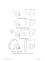
1. General Information
The Hastings HPM-2002-OBE is a small, low cost electronics module which provides the user with
accurate vacuum measurements over a wide range of pressure. The HPM-2002-OBE uses the same rugged
HPM-2002s transducer tube as the HPM-2002 bench top instrument. This tube features two sensors; a
patented thin-film Pirani sensor and a piezoresistive sensor combined in a single tube with a matched EEPROM
(Electrically Erasable/Programmable Read Only Memory).
The HPM-2002-OBE electronics module combined with the HPM-2002’s tube provides accurate vacuum
measurement from 1x10⁻⁴ Torr to 1000 Torr. The HPM-2002-OBE is designed for quick, easy installation and
will provide the user with long lasting, trouble free, reliable vacuum measurement.
1.1. Features:
•
•
•
•
•
•
•
Low-Cost Electronics Module
Wide Dynamic Range 1x10⁻⁴ Torr to 1000 Torr
Combined Sensors in a Single Tube
Input Voltage (11.5-30 VDC)
Connector: 15-pin high-density male “D”
Optional 4-digit LED Display
Optional Outputs (Dual 0-10 volt analog or RS232/485)
1.2. Model 2002 Sensors
The Model 2002 transducer tube is comprised of an ion implanted piezoresistive, direct force sensor and a
thin film Pirani type sensor. The Pirani sensing element is a Pt thin film serpentine element deposited on a 1
micron thick Si3N4 membrane. The membrane is peripherally supported by a Si box shaped die and is covered
by a thick Si lid parallel to the membrane and open on two ends. The piezoresistive unit is an ion implanted
Wheatstone bridge in a 50 micron thick Si membrane peripherally supported by a Si box shaped die which has
been anodically bonded to a Pyrex substrate.
The dual sensor assembly is encased in a corrosion resistant 316 stainless steel tube shell. The durable tube
design withstands high pressure (150 psig/10.2 bar) and high pressure surges. Since the Pirani sensor is
miniaturized and employs a Pt thin film on a Si3N4 membrane (instead of a conventional long fragile wire), the
transducer can withstand high levels of mechanical shock.
The Model 2002 is designed for fast response. The micro machined sensing elements have a very small
mass and operate in a constant temperature (Pirani) and a constant current (piezo) feedback mode. This makes
response time very fast as compared to other commercially available sensors which have to change the
temperature of a significant mass to reflect pressure changes and have a large internal volume which must
equalize in pressure with the system before the sensor can reach its final value. The transducer’s small internal
volume (<1.5 cc) permits rapid pneumatic response to system pressure changes. Further, the small geometry of
the transducer prevents thermal convection currents which allows the sensor to be mounted in any orientation
without calibration shifts.
1.3. HPM-2002-OBE Analog Output Module
The analog output (0-10 V) module consists of a power conversion/sensor transducer board,
microprocessor board and a user interface option board. Two 0-10 Volt linear outputs are generated for the user
via the high-density 15-pin “D” connector. The first of these outputs covers the pressure range from 0 to 1024
Torr. The second output covers the range from 0 to 1000 mTorr. A four digit floating-point LED display is
standard.
1.4. HPM-2002-OBE Analog Output (4-20mA) Module
(Identical to 1.3, except replace 0-10 V with 4-20 mA)
HPM-2002-OBEVacuum Gauge
Page 5 of 39
1.5. HPM-2002-OBE RS232/485 Output Module
The RS232/485 module consists of a power conversion/sensor transducer board, microprocessor board and
a user interface option board. Serial communication is conducted via an RJ-11 type connector. With RS232
option (EIA-232 Rev. E) communication can easily be established between the module and the serial port of a
PC. The RS485 option allows the user to address multiple units and allows operation at distances of up to 4000
feet. The RS232/485 module includes a four digit floating-point LED display.
1.6. HPM-2002-OBE DeviceNet Module
The DeviceNet module consists of a power conversion/sensor transducer board, microprocessor board and
a user interface option board. All communication is conducted via a 5-pin “Micro” style with center pin, male
pin contacts. The module has passed the ODVA DeviceNet test and conforms to the vacuum/pressure gauge
device profile, an Electronic Data Sheet (EDS) with limited features is also available upon request.
1.7. Specifications
Measuring range ............................................................................................................. 1x10⁻⁴ to 10+3 Torr
..............................................................................................................................1.3x10-4 to 1.3x10+3 mbar
Accuracy (N2, T=23°C) .................................................................. + 20% of reading (1 x10⁻³ to 50 Torr)
............................................................................................................ + 1.5% of reading (50 to 1000 Torr)
Ambient temperature operating range........................................................................................... 0° to 50°C
Process control ......................................................... 2 TTL outputs (1 TTL remote zero command input)
Digital readout....................................................................................................................... Four digit LED
Equipment operating ranges .......................................................................................................12-30 VDC
Transducer mounting ............................................................................ Any position without recalibration.
Transducer internal volume .............................................................................................................. < 1.5 cc
Wetted material ...................................................................................................... Au, Si3N4, Si, PyrexTM,
.................................................................................................................... KovarTM, 316 stainless steel and
.................................................................................................... High Temp/Low Outgassing UHV Epoxy
Weight (OBE & HPM-2002s tube) .......................................................................... 12 oz (1/8” NPT tube)
Calibrated for nitrogen .....................................................Conversion Factors for other gases are selectable
Burst Pressure (Tube)...................................................................................................................... 150 psig
Proof Pressure (*) .............................................................................................................................. 30 psig
Nominal Operating Pressure (Tube) .............................................................................. 1x10⁻⁴ to 10+3 Torr
Input Operating Range ........................................................................................................ 11.5 to 30 VDC
Input Power.................................................................................................................... 24 VDC @ 125 mA
* Maximum pressure above which may cause permanent damage.
HPM-2002-OBEVacuum Gauge
Page 6 of 39
2. Installation
This section is designed to assist in getting a new pressure gauge into operation as quickly and easily as
possible. Please read the following instructions thoroughly before installing the instrument.
2.1. Receiving Inspection
Carefully unpack the Hastings Model HPM-2002-OBE Instrument (part # HPM-2002-OBE), and
transducer tube (part #HPM 2002s-xx). Inspect all items for any obvious signs of damage due to shipment.
Immediately advise the carrier who delivered the shipment if any damage is suspected.
Compare each component shipped against the packing list. Ensure that all parts are present (i.e. transducer,
electronics module, hardware, etc.). Optional equipment or accessories will be listed separately on the packing
list.
2.2. Quick Start
•
•
•
•
•
•
•
•
•
•
•
•
•
•
Unpack and inspect all items for any obvious signs of damage due to shipment. Immediately advise the
carrier who delivered the shipment if any damage is suspected.
Wire the 15-pin “D” connector according to cable pinout (see Table below) using 24 AWG or other
suitable wire.
Using a unipolar DC Power Supply, set the desired operating voltage within the range of 12 VDC to
30 VDC.
Connect the HPM-2002-OBE module to the HPM-2002s transducer tube.
Note that the connector is keyed.
A finger tight connection is all that is required for adequate operation.
Transducer tube may be installed in any orientation. However, if condensation is likely to occur, then
the tube port should be orientated downward.
When installing 1/8” NPT style transducer tube, use the 7/16” wrench flats.
Attach cable.
With the vacuum chamber at atmosphere, turn on the power supply (typically +24 VDC. Gauge is
now reading pressure.
For best accuracy, the gauge should now be zeroed. Pump the vacuum system down to low (10-6 Torr)
pressure if possible. Ideally the gauge should be operated in this condition for one hour before setting
the “Zero”.
To set the “Zero”, place the HPM-2002-OBE in the “CAL” mode by using the “SELECT” button.
Using a small flat head screwdriver, rotate the “ADJUST” rotary encoder until the unit flashes
between “0.0” and “-0.0”.
Return to the “RUN” mode by using the “SELECT” button
2.3. Transducer Installation
The transducer tube may be installed in any orientation. Although the transducer tube is rugged and will
perform well in many harsh environments, the tube should be installed in a clean and careful manner. The tube
is configured with the vacuum fitting requested. If your vacuum environment is highly contaminated or has
unique fitting requirements, a Hastings filter or special adapter may be needed. Please contact the Hastings
Instruments Sales Department for assistance in your system configuration.
2.4. OBE Module Installation
•
•
•
•
Environment:
Indoor use
Altitude up to 2000 meters
Operating temperature range from 5 to 40°C
HPM-2002-OBEVacuum Gauge
Page 7 of 39
•
•
Maximum relative humidity: 80% for temperatures up to 31°C decreasing linearly to 50% relative
humidity at 40°C.
Installation category II
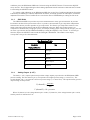
HPM-2002-OBE
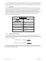
CABLE PINOUT
Analog Ouput
Analog Ouput
Digital Output
Pin
No.
0-10 Volt
4-20 mA
RS232/485
1
2
3
4
5
6
7
8
9
10
11
12
13
14
15
High Setpoint Output
Low Setpoint Output
Power Input (+12 to 30 VDC)
Power Return
Channel 1 Vout (+)
Analog Return
Channel 2 Vout (+)
Digital Ground
Remote Zero
NC
NC
NC
NC
Rx In (Internal Use)
Tx Out (Internal Use)
High Setpoint Output
Low Setpoint Output
Power Input (+12 to 30 VDC)
Power Return
Channel 1 Iout (-)
Analog Shield
Channel 2 Iout (-)
Digital Ground
Remote Zero
Channel 1 Iout (+)
Channel 2 Iout (+)
NC
NC
Rx In (Internal Use)
Tx Out (Internal Use)
High Setpoint Output
Low Setpoint Output
Power Input (+12 to 30 VDC)
Power Return
NC
NC
NC
Digital Ground
Remote Zero
NC
NC
NC
NC
NC
NC
2.5. Initial Operation
Upon applying power to the control unit a pressure measurement will be given in Torr for nitrogen.
However, it is recommended that the user follow the instructions for zeroing and adjusting the output at
atmosphere.
HPM-2002-OBEVacuum Gauge
Page 8 of 39
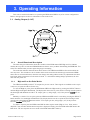
3. Operating Information
This section contains information on operating the HPM-2002-OBE in any of its various configurations.
Refer to the appropriate section for information on the mode in use.
3.1. Analog Output (0-10V)
3.1.1.
Overall Functional Description
The status bar gives information about the condition of the HPM-2002-OBE. High and Low indicate
whether the set points are activated. ERROR indicates if there was a problem downloading the EEPROM. Torr
and mTorr indicate what pressure regime the gauge is measuring.
The mode bar indicates which mode has been selected. The HPM-2002-OBE has five modes which the
user may enter. This is similar to the six modes which can be entered in the bench top/panel mounted HPM2002, there is no interlock feature; when the user changes the setting within a mode, any adjustments that have
been made will be permanent once the mode is exited. To exit without making changes permanent, the user
must turn the power off.
3.1.2.
High and Low Set Point Modes
The HPM-2002-OBE provides TTL outputs for process control. These signals are available on the 15-pin
connector (see previous table in Section 2.4).
To view the High set point, place the HPM-2002-OBE in the High mode by pressing the SELECT button
until the High mode light is illuminated. The display then shows the set point selected. During normal operation
the alarm light will illuminate and the TTL output (pin # 1) will go high (+5V) if the pressure exceeds the set
point.
Similarly, to view the Low set point, place the HPM-2002-OBE in the Low mode by pressing the SELECT
button until the Low mode light is illuminated. The display then shows the set point selected. During normal
operation the alarm light will illuminate and the TTL output (pin # 2) will go high (+5V) if the pressure
becomes less than the set point.
To adjust a setpoint, place the HPM-2002-OBE in either setpoint mode (High or Low). Next, use the
ADJUST rotary encoder until the desired setpoint is displayed. Finally, place the HPM-2002-OBE back in the
Run mode. The new setpoints are now stored in the HPM-2002-OBE’s memory.
HPM-2002-OBEVacuum Gauge
Page 9 of 39
3.1.3.
Run Mode
The HPM-2002-OBE will automatically enter the Run mode upon start-up. This is the mode for normal
operation and the mode in which the instrument will spend most of its time. In the Run mode the HPM-2002OBE will continuously monitor the pressure, update the alarm conditions, and update the display about ten
times a second.
3.1.4.
Cal Mode
Optimal performance of the HPM-2002-OBE is achieved by performing in situ adjustments to the
calibration coefficients in the Cal mode. There are three calibration coefficients. These are the zero coefficient,
the midrange coefficient, and the atmosphere coefficient. Once a tube has been fully calibrated the midrange
coefficient should never need further adjustment, but it may be helpful to adjust the zero coefficient or the
atmosphere coefficient under certain circumstances. The CAL MODE presupposes that the operator is
applying a known pressure of the correct gas composition (see GAS MODE). The factory calibration points are
800 Torr, 7 Torr, and < 10-6 Torr. The user’s calibration points are not required to be exactly those values, but
should be somewhat close, and must be within the ranges shown in the following figure. The HPM-2002-OBE
detects the voltage signal within the sensor tube, which is converted and displayed as a pressure reading. The
resulting pressure reading determines which of the three coefficients will be adjusted.
The operator action is the same for adjustment of all three of the coefficients, except that he must apply the
proper calibration pressures according to the calibration point he is about to adjust. To adjust a calibration
HPM-2002-OBEVacuum Gauge
Page 10 of 39
coefficient, place the HPM-2002-OBE in the Cal mode using the SELECT button. Then turn the ADJUST
rotary encoder. The Cal light will begin to flash during adjustment and will continue to flash until the Cal mode
is exited using the SELECT button.
To perform a full calibration on the HPM-2002-OBE, first use the Zero Coefficient Adjustment Procedure.
Followed by the Midrange Coefficient Adjustment Procedure, and finally perform the Atmosphere Coefficient
Adjustment Procedure. Sensor Coefficients are stored in the Sensor’s EEPROM upon exiting the Cal mode.
3.1.5.
GAS Mode
The HPM-2002-OBE can provide true pressure measurements in many gas environments. At pressure
levels where the direct force piezoresistive sensor is operative, the instrument is gas composition independent
and measures the true pressure regardless of gas composition. The Pirani is gas composition sensitive so the
actual composition must be known and the Pirani calibrated in that gas. When the vacuum system’s gas
composition is dominated by a single gas species (for example, during system venting with an inert gas), the user
can enter a gas selection into the HPM-2002-OBE by rotating the ADJUST rotary encoder. To view the gas
selection, depress the SELECT button until the GAS light is illuminated. The number on the display
corresponds to the gas. See the table below.
Gas Selection Table
Gas Mode
Gas
Displayed Number
3.1.6.
00
Nitrogen
01
Argon
02
Helium
03
Water Vapor
04
Custom
Analog Output (0-10V)
The dual (0 - 10V) output option board provides voltage outputs proportional to the HPM-2002-OBE’s
pressure reading. The first channel (pin 5) corresponds to the higher-pressure range (0 - 1024 Torr). The
second channel (pin 7) corresponds to the lower pressure range (0 - 1000 mTorr). The equation below gives the
output voltage on the pressure:
V (channel1) =
pressure
100
V (channel 2) = 10 × pressure
Where V(channel 1) is the voltage between pins 5 and 6, V(channel 2) is the voltage between pins 7 and 6,
and the pressure is indicated in Torr.
HPM-2002-OBEVacuum Gauge
Page 11 of 39
HPM-2002-OBEVacuum Gauge
Page 12 of 39
3.2. Analog Output (4-20mA)
The HPM-2002-OBE with analog output and display is shown in the figure below. The user interface
consists of a status bar, a mode bar, and setpoint test jacks.
3.2.1.
Overall Functional Description
The status bar gives information about the condition of the HPM-2002-OBE. High and Low indicate
whether the set points are activated. Error indicates if there was a problem downloading the EEPROM. Torr
and mTorr indicate what pressure regime the gauge is measuring.
The mode bar indicates which mode has been selected. The HPM-2002-OBE has five modes which the
user may enter. This is similar to the six modes which can be entered in the bench top/panel mounted HPM2002, there is no interlock feature; when the user changes the settings within a mode any adjustments that have
been made will be permanent once the mode is exited. (To exit without making changes permanent, the user
must turn the power off.)
3.2.2.
High and Low Set Point Modes
The HPM-2002-OBE provides TTL outputs for process control. These signals are available on the 15-pin
connector (see previous table in Section 2.4).
To view the High set point, place the HPM-2002-OBE in the High mode by pressing the SELECT button
until the High mode light is illuminated. The display then shows the set point selected. During normal operation
the alarm light will illuminate and the TTL output (pin # 1) will go high (+5V) if the pressure exceeds the set
point.
Similarly, to view the Low set point, place the HPM-2002-OBE in the Low mode by pressing the SELECT
button until the Low mode light is illuminated. The display then shows the set point selected. During normal
operation the alarm light will illuminate and the TTL output (pin # 2) will go high (+5V) if the pressure
becomes less than the set point.
To adjust a setpoint, place the HPM-2002-OBE in either setpoint mode (High or Low). Next, use the
ADJUST rotary encoder until the desired setpoint is displayed. Finally, place the HPM-2002-OBE back in the
Run mode. The new set points are now stored in the HPM-2002-OBE’s memory.
3.2.3.
Run Mode
The HPM-2002-OBE will automatically enter the Run mode upon start-up. This is the mode for normal
operation and the mode in which the instrument will spend most of its time. In the Run mode the HPM-2002-
HPM-2002-OBEVacuum Gauge
Page 13 of 39
OBE will continuously monitor the pressure, update the alarm conditions, and update both analog output
channels about ten times a second.
3.2.4.
Cal Mode
Optimal performance of the HPM-2002-OBE is achieved by performing in situ adjustments to the
calibration coefficients in the Cal mode. There are three calibration coefficients. These are the zero coefficient,
the midrange coefficient, and the atmosphere coefficient. Once a tube has been fully calibrated the midrange
coefficient should never need further adjustment, but it may be helpful to adjust the zero coefficient or the
atmosphere coefficient under certain circumstances.
The CAL MODE presupposes that the operator is applying a known pressure of the correct gas
composition (see GAS MODE). The factory calibration points are 800 Torr, 7 Torr, and < 10-6 Torr. The
user’s calibration points are not required to be exactly those values, but should be somewhat close, and must be
within the ranges shown in the following figure. The HPM-2002-OBE detects the voltage signal within the
sensor tube, which is converted and displayed as a pressure reading. The resulting pressure reading determines
which of the three coefficients will be adjusted
The operator action is the same for adjustment of all three of the coefficients, except that he must apply the
proper calibration pressures according to the calibration point he is about to adjust. To adjust a calibration
coefficient, place the HPM-2002-OBE in the Cal mode using the SELECT button. Then turn the ADJUST
rotary encoder. The Cal light will begin to flash during adjustment and will continue to flash until the Cal mode
is exited using the SELECT button.
HPM-2002-OBEVacuum Gauge
Page 14 of 39
To perform a full calibration on the HPM-2002-OBE, first use the Zero Coefficient Adjustment Procedure.
Followed by the Midrange Coefficient Adjustment Procedure, and finally perform the Atmosphere Coefficient
Adjustment Procedure. Sensor Coefficients are stored in the Sensor’s EEPROM upon exiting the Cal mode.
3.2.5.
GAS Mode
The HPM-2002-OBE can provide true pressure measurements in many gas environments. At pressure
levels where the direct force piezoresistive sensor is operative, the instrument is gas composition independent
and measures the true pressure regardless of gas composition. The Pirani is gas composition sensitive so the
actual composition must be known and the Pirani calibrated in that gas. When the vacuum system’s gas
composition is dominated by a single gas species (for example, during system venting with an inert gas), the user
can enter a gas selection into the HPM-2002-OBE by rotating the ADJUST rotary encoder. To view the gas
selection, depress the SELECT button until the GAS light is illuminated. The number on the display
corresponds to the gas. See the table below.
Gas Selection Table
Gas Mode
Gas
Displayed Number
3.2.6.
00
Nitrogen
01
Argon
02
Helium
03
Water Vapor
04
Custom
Analog Output (4-20mA)
The dual output option board provides current output proportional to the HPM-2002-OBE’s pressure
reading. The first channel (pins 5 & 10) corresponds to the higher-pressure range (1-1024 Torr). The second
channel (pins 7 & 11) corresponds to the lower pressure range (0-1000 mTorr). The equation below gives the
output current of the pressure:
Ι(channel1) = 4mA + (p(Torr ))*
16mA
1024Torr
⎛ 16mA ⎞
Ι(channel 2 ) = 4mA + ( p(mTorr )) * ⎜
⎟
⎝ 1000 mTorr ⎠
Note that for both channels, the output is always between 4mA and 20mA specifically, when the pressure goes
below 1 Torr, channel 1 current will be approaching its minimum of 4mA and when the pressure is above 1
Torr, channel 2 current will be 20mA.
HPM-2002-OBEVacuum Gauge
Page 15 of 39
HPM-2002-OBEVacuum Gauge
Page 16 of 39
3.3. RS232/485 With Display
The HPM-2002-OBE with RS232/485 output and display is shown in the figure below. The user interface
consists of 4-digit LED display, a status bar, and a mode bar.
3.3.1.
Overall Functional Description
The status bar gives information about the condition of the HPM-2002-OBE. High and Low indicate
whether the set points are activated. Error indicates if there was a problem downloading the EEPROM. Torr
and mTorr indicate what pressure regime the gauge is measuring.
The mode bar indicates which mode has been selected. The HPM-2002-OBE has five modes which the
user may enter. This is similar to the six modes which can be entered in the standard HPM-2002, there is no
interlock feature; when the user changes the settings within a mode any adjustments that have been made will be
permanent once the mode is exited. (To exit without making changes permanent, the user must turn the power
off.)
Communication with the serial interface of the HPM-2002-OBE is via an ASCII data string. In the RS-232
mode the command message consist only of a command string and the terminator. The attention character and
address string are not required, but if they are used they MUST be valid. If all components of the ASCII data
string are valid the command will be accepted and executed. The RS-232 mode is sometimes referred to as
point-to-point mode since only one device may be connected to the controller at any given time.
A message to the HPM-2002-OBE in the RS-485 mode consists of an attention character followed by the
address string, the command string, and the terminator. If all components of the ASCII data string are valid the
command will be accepted and executed. The RS-485 mode is also referred to as multipoint mode since up to
31 devices may be connected to the same controller in a network scheme.
3.3.2.
COMMAND SYNTAX
In the following examples of syntax codes, the special characters are explained:
The characters in square brackets [ ] represents a command string, either upper or lower case command
characters accepted. All characters must follow each other in the string with no spaces or other characters.
HPM-2002-OBEVacuum Gauge
Page 17 of 39
The characters within wavy brackets { } contain choices for the appropriate command.
The characters within the symbols < > are the common abbreviations for the one digit ASCII control codes
which they represent, (e.g. <CR> represents carriage return).
When entering more than one command in the same data string, they must be separated by a comma.
All command strings must be followed by the terminator character (carriage return <CR>, also known as
ENTER).
When a lower case character is present in an example it represents an option.
3.3.3.
Character
Description
Valid Inputs:
a
RS-485 Address (hexadecimal 0-9, A-F)
01 - DF
m
Most Significant Digit Of Mantissa
1-9
d
Decimal Digit
0-9
e
Exponent
0-5
u
Unit Of Pressure
T, M, or P
,
Command Separator (comma)
N/A
<CR>
Command Terminator (carriage return)
N/A
Interrogation Commands
Command Description
Format
Transmit Averaged Pressure
P<CR> Pa: 1.23456e+0 Torr<CR>
Transmit Pirani Pressure
R<CR>Pr: 1.98765e-3 Torr<CR>
Transmit Piezo Pressure
Z<CR> Pz: 7.65432e+2 Torr<CR>
Transmit RS-485 Address
A<CR>Multidrop Address: 01<CR>
Transmit Decimation Ratio
D<CR>
Decimation Ratio: 255<CR>
Transmit Selected Gas #
G<CR>
Gas#: 0<CR>
Transmit High Setpoint
H<CR>
Hi: 1.00000e+1 Torr<CR>
Transmit Low Setpoint
L<CR> Lo: 1.00000e-2 Torr<CR>
Transmit Device Status
S<CR> 00044<CR>
Transmit Turnaround Delay
T<CR>
Comm Delay: 6<CR>
Transmit Selected Units
U<CR>
Torr<CR>
Transmit Software Version #
Sample Response
V<CR>Hastings Instruments-OBE 2002
Version 1.4 - (7-21-00) <CR>
3.3.4.
Paramater Modification Commands
Command Description
Format
Valid Range:
Modify High Setpoint
Modify Low Setpoint
Modify Selected Gas #
Modify Selected Units
Modify Decimation Ratio
Modify RS-485 Address
Modify Turnaround Delay
H={m.dd}E{+e}<CR> 1.00000e-9 to 9.99999e+9
L={m.dd}E{-e}<CR>
1.00000e-9 to 9.99999e+9
G={d}<CR>
0 to 4
(Decimal)
U={u}<CR>
T, or M, or P
D={dddd}<CR>
63 to 7936
(Decimal)
*{aa}A={aa}<CR>
1 to DF (Hexadecimal)
*{aa}T={dd}<CR>
0 to 255 (Decimal)
Notes:
HPM-2002-OBEVacuum Gauge
Page 18 of 39
The setpoints may also be entered as a decimal number, e.g. [H=760.99<CR>] will be same as entering
[H=7.6099E+2<CR>] .
When inputting setpoint data, it should be entered in the same Units of Pressure as the presently selected
Units of Measurement (i.e. Torr, mbar or Pascal). The data is only checked to be a valid number with a one
digit exponent before being accepted. There are no limit checks on the data; the user is free to choose any value
appropriate to his use of the instrument.
The Turnaround Delay and RS-485 address are unique to multipoint communications. In order to prevent
inadvertent modifications of these parameters, the multipoint attention character and the Model 2002’s present
address [*{aa}] MUST be used and are checked for validity before the command is executed.
If the RS-485 address is unknown, the ‘UNIVERSAL ADDRESS’ [*00] may be used to set the address to a
known value, e.g. [*00A=35<CR>] will change the RS-485 address to 35.
Caution: Since all units will respond to the ‘UNIVERSAL ADDRESS’, make sure that only the unit to be
modified is connected to the RS-485 Bus. If more than one unit is connected, this will result in all of the units
being set to the same address.
The ‘UNIVERSAL ADDRESS’ is used for setup only; (i.e. to set all units to the same gas #) data is never
transmitted when the ‘UNIVERSAL ADDRESS’ is used.
The value entered for the Turnaround Delay is used to modify an internal timer which normally runs at ~8
millisecond, e.g. [*{aa}T=10<CR>] will set the delay to ~80 milliseconds.
If the command syntax is not met or if the number is out or range, the HPM-2002 will respond with the
ASCII codes for <bell>?<CR>, and the command will be ignored.
3.3.5.
Calibration Adjustment Commands
Command Description
Format
Valid Range:
Set Full Scale Calibration
CF={m.d}E{e}<CR>
5.12e+2 to 1.023e+3 Torr
6.83e+2 to 1.365e+3 mbar
6.83e+4 to 1.365e+5 Pascal
Set Midpoint Calibration
CM={m.d}E{e}<CR>
4.00e+0 to 7.999e+0 Torr
5.34e+0 to 1.066e+1 mbar
5.34e+2 to 1.066e+3 Pascal
Set Low Scale Calibration
CL={m.d}E{e}<CR>
0 to 1.2499e-1 Torr
0 to 1.666e-1 mbar
0 to 1.666e+1 Pascal
Notes:
The calibration adjustment data may also be entered as a decimal number, e.g. [CF=760.99<CR>] will be
same as entering [CF=7.6099E+2<CR>].
When inputting calibration adjustment data, it must be within the valid range of the presently selected Unit
of Measurement (i.e. Torr, mbar or Pascal). The data is checked to be valid before being accepted.
If the command syntax is not met or if the number is out or range, the HPM-2002-OBE will respond with
the ASCII codes for <bell>?<CR> and the command will be ignored.
The ‘UNIVERSAL ADDRESS’ may be used to calibrate all connected units simultaneously, e.g.
[*00CF=760<CR>].
3.3.6.
Reset / Restore Commands
Command Description
Escape
Format
<Esc>
Notes:
Reset Command Buffer (ignore prior Input)
Software Reset
/R<CR>
Reinitialize Software
HPM-2002-OBEVacuum Gauge
Page 19 of 39
3.3.7.
Restore Factory Defaults
/#<CR>
Restore Calibration Register Default Values
Set Zero
/0 <CR>
Store Present Pressure as Instrument ZERO
(if Piezo <32 Torr & Pirani <50 mTorr)
Force Zero
/!<CR> Override Limit Checks and Store Present
Pressure as Instrument ZERO
Device Status
When requested to transmit its status the HPM-2002-OBE responds with a five digit number which is
explained in the following:
digit#:
Serial Receiver Overflow
Main Board EEPROM Error
Probe EEPROM (any) Error
Probe EEPROM Not Responding
Probe EEPROM Read Error
1
2
3
4
5
=4
=2
=1
=8
=1
Probe EEPROM Checksum Error
Probe EEPROM Verification Error
Probe EEPROM Identification Error
Communications Syntax Error
Piezo Sensor Bad (voltage out of range)
Pirani Sensor Bad (voltage out of range)
High Setpoint Alarm (pressure exceeds setpoint)
Low Setpoint Alarm (pressure less than setpoint)
Gas# Changed (not the same as when unit last calibrated)
=4
=2
=1
=4
=2
=1
=4
=2
=1
3.3.8.
Default RS232/485 Specifications
Baud Rate ..................................................................................................................................... 9600
Character Length .......................................................................................................... Eight data bits
Parity ........................................................................................................................................... None
Stop Bits ............................................................................................................................................. 1
RS 485 Universal Address ................................................................................................................ 00
HPM-2002-OBEVacuum Gauge
Page 20 of 39
3.3.9.
Modular Connector Pinout (R2-232) RJ-11 connector on left side.
Pin #1 .............................................................................. Ready to receive (output signal from OBE)
Pin #2 .......................................................................................................... Data (output from OBE)
Pin #3 and #4 ....................................................................................... Common Ground Reference
Pin #5 ................................................................................................................. Data (input to OBE)
Pin #6 .......................................................................................... Clear to send (input signal to OBE)
A common application of the RS232 version of the HPM-2002-OBE is to connect the pressure gauge
directly to the serial port of a PC. This is done by first wiring the supplied communication cable in the manner
shown below:
3.3.10.
Modular Connector Pinout (RS-485)
The two RJ-11 Connectors are “Feed Thru” connections, since they are wired in parallel (see above fig.).
RS 485 half duplex
RS 485 full duplex
Pin #1
T+/R+
Pin #1
T+
Pin #2
T-/R-
Pin #2
T-
Pin #3
GND
Pin #3
GND
Pin #4
GND
Pin #4
GND
Pin #5
n/a
Pin #5
R-
Pin #6
n/a
Pin #6
R+
3.3.11.
High and Low Set Point Modes
The HPM-2002-OBE provides TTL outputs for process control. These signals are available on the 15-pin
connector (see previous table in Section 2.4).
The High set point can be viewed using either the display or the serial connection. To view the high
setpoint, place the HPM-2002-OBE in the High mode by pressing the Select button until the High light (on the
mode bar) is illuminated. The display then shows the set point selected. During normal operation the alarm
light will illuminate and the TTL output (pin # 1) will go high (+5V) if the pressure exceeds the set point. To
view the setpoint using the serial connection, send “H<CR>”.
Similarly, to view the Low set point, place the HPM-2002-OBE in the Low mode by pressing the SELECT
button until the Low light (on the mode bar) is illuminated. The display then shows the set point selected.
HPM-2002-OBEVacuum Gauge
Page 21 of 39
During normal operation the alarm light will illuminate and the TTL output (pin # 2) will go high (+5V) if the
pressure becomes less than the set point.
To view the setpoint using the serial connection, send “L<CR>”.
The set points can be adjusted using either the controls on the gauge or the serial connection. To adjust a
setpoint using the manual controls, place the HPM-2002-OBE in either setpoint mode (High or Low). Next, use
the ADJUST rotary encoder until the desired setpoint is displayed. Finally, place the HPM-2002-OBE back in
the Run mode. The new set points are now stored in the HPM-2002-OBE’s memory. Or simply use one of the
Modify High Setpoint Commands e.g. “H={m.dd}E{=+e}<CR>”.
3.3.12.
Run Mode
The HPM-2002-OBE will automatically enter the Run mode upon start-up. This is the mode for normal
operation and the mode in which the instrument will spend most of its time. In the Run mode the HPM-2002OBE will continuously monitor the pressure; update the alarm conditions, and update the display about ten
times a second.
3.3.13.
Cal Mode
Optimal performance of the HPM-2002-OBE is achieved by performing in situ adjustments to the
calibration coefficients in the Cal mode. There are three calibration coefficients. These are the zero coefficients,
the midrange coefficient, and the atmosphere coefficient. Once a tube has been fully calibrated the midrange
coefficient should never need further adjustment, but it may be helpful to adjust the zero coefficient or the
atmosphere coefficient under certain circumstances. The CAL MODE presupposes that the operator is applying
a known pressure of the correct gas composition (see GAS MODE). The factory calibration points are 800
Torr, 7 Torr, and < 10-6 Torr. The user’s calibration points are not required to be exactly those values, but
should be somewhat close, and must be within the ranges shown in the figure on page 15. The HPM-2002OBE detects the voltage signal within the sensor tube, which is converted and displayed as a pressure reading.
The resulting pressure reading determines which of the three coefficients will be adjusted.
HPM-2002-OBEVacuum Gauge
Page 22 of 39
3.4. DeviceNet TM
The HPM-2002-OBE with DeviceNet option is shown in figure below.
3.4.1.
Overall Functional Description
The DeviceNet module consists of a power conversion/sensor transducer board, microprocessor
board
and a user interface option board. All communication is conducted via a 5-pin “Micro” style with center pin,
male pin contacts. The module has passed the ODVA DeviceNet test and conforms to the vacuum/pressure
gauge device profile; an Electronic Data Sheet (EDS) with limited features is also available upon request.
3.4.2.
DeviceNet description
DeviceNet is a low-level network that provides connections between industrial devices (sensors and
actuators) and higher-level devices (controllers). Both power and high speed digital signaling are contained
within the same cable. Controller Area Network (CAN) protocol is used to transfer commands and data across
the bus. Up to 64 nodes are addressable per network.
Some of the user benefits of using DeviceNet are:
•
•
Reduced hardwiring and reduced start-up time through the use of standardized cables for the Trunk
and Branch lines, in addition to standardized Taps for making physical interconnections.
Ease of integrating products from multiple vendors. More than 250 vendors produce DeviceNet
products.
For more information, contact the Open DeviceNet Vendor Association (ODVA) at their web site.
http://www.odva.org
HPM-2002-OBEVacuum Gauge
Page 23 of 39
3.5. Calibration of the HPM-2002-OBE
3.5.1.
Zero Coefficient Adjustment
The zero coefficient corrects for the constant power level which is present over the entire pressure range.
Typically, this adjustment corrects for low pressure errors. The instrument will need to be re-zeroed often if
measurements are being made in the 10-4 Torr range, especially if the ambient temperature changes. The transducer
may have a temperature coefficient of up to 2x10⁻⁴ Torr/oC. The instrument remote zero input will allow an external
gauge such as an ion gauge to automatically re-zero the HPM-2002-OBE whenever the pressure drops below the desired
pressure level (if it has a TTL output).
NOTE: Do not attempt to zero the Model 2002 in pressures above 10-2 Torr; the microprocessor will not accept a
zero above this pressure.
To manually adjust the zero use the following procedure:
1.
If possible, evacuate the vacuum system into the low 10-6 Torr (1.33x10⁻⁶ mbar) range or as low as possible
below 10-4 Torr.
2.
Allow the sensor to operate in this condition for a minimum of 15 minutes.
3.
Place the instrument in the CAL mode, using the “SELECT” button, then turn the “ADJUST” rotary encoder.
The CAL light will start to flash indicating that the calibration mode has been activated.
4.
Use ADJUST until the display reads 0.0 (or 0.0 with an occasional -0.0). OR using the RS232/485 send
“/0<CR>”.
5.
The unit is now fully zeroed. Place the HPM-2002-OBE back in the RUN mode to store the zero in permanent
memory.
3.5.2.
Midrange Coefficient Adjustment
The midrange coefficient corrects for errors in the slope of the power curve of the thin film Pirani.
Typically, this is due to the geometry of a particular sensor and will only need to be performed once in the
lifetime of the sensor. This adjustment might be needed if a full calibration is being performed in a gas other than
nitrogen. The zero adjustment will need to be performed before making this adjustment.
To adjust the midrange coefficient use the following procedure:
1.
Evacuate the vacuum chamber and refill with the desired gas to a pressure of 7 Torr, as indicated by a
reference vacuum gauge.
2.
Place the instrument in the Cal mode using the SELECT button.
3.
Turn the ADJUST rotary encoder until the HPM-2002-OBE display matches the reading on the reference
gauge OR using the RS232/485 send “CM={m.d}E{e}<CR>”.
4.
Place the HPM-2002-OBE back in the Run mode.
3.5.3.
Atmosphere Coefficient Adjustment
If a reference high pressure gauge is not available, the ambient barometric pressure acquired from the
weather channel or other weather service can be used to adjust the proper reading.
To adjust the atmosphere coefficient, use the following procedure:
1.
Backfill with the desired gas to a pressure between 700 and 800 Torr.
2.
Place the instrument in the Cal mode using the SELECT button.
3.
Turn the ADJUST rotary encoder until the HPM-2002-OBE display matches the reading on the reference
gauge OR using the RS232/485 send “CM={m.d}E{e}<CR>”.Place the HPM-2002-OBE back in the Run
mode.
HPM-2002-OBEVacuum Gauge
Page 24 of 39
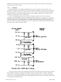
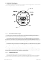
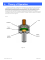
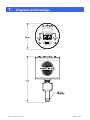
4.
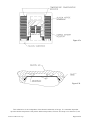
Theory of Operation
The 2002s transducer tube is comprised of two very different sensors which provide a span of measurement
extending from 1000 Torr down to less than 1 × 10⁻⁴ Torr. The piezoresistive device is a direct force sensor
which provides pressure indication from 1000 Torr down to less than 1 Torr. The thin film Pirani device is a
thermal conductivity sensor that provides pressure indication from 100 Torr down to less than 1 × 10⁻⁴ Torr.
The two decade overlap in measurement range is convenient for smooth transition either descending or
ascending in pressure. Both sensors are small micro machined die that are bonded to a Au coated Al2O3 preform
(stress-isolation) which in turn is bonded to a TO-8 header. The header is resistance welded into a 316 stainless
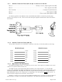
steel envelope as shown in the Figure 4.1.
4.1.1.
PCB
EEPROM
TO-8
HEADER
PIRANI
SENSOR
PIEZO
SENSOR
Figure 4.1
HPM-2002-OBEVacuum Gauge
Page 25 of 39
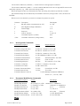
4.2. Piezoresistive Sensor
Figure 4.2 shows a typical schematic of a Boron ion implanted Wheatstone bridge network in a Si
diaphragm inverted box type geometry. The inside of the box is evacuated during anodic bonding to a Pyrex
substrate. The membrane has maximum deflection at atmosphere (or higher pressure) and the membrane
resistances change value as the differential pressure is decreased during pump down. The resulting differential
output is
Vo = SPV+V1
where
S is the sensitivity
P is the pressure
V is the applied bridge voltage
V1 is the no load output voltage
Since the sensitivity changes so dramatically with temperature, some correction is required for
compensation. The change in output voltage
dVo
⎛ SdV VdS ⎞
= P⎜
+
⎟
dT
dT ⎠
⎝ dT
To insure temperature invariance,
therefore
dVo
=0
dT
1 dV
⎛ 1 dS ⎞
= −⎜ +
⎟
V dT
⎝ S dT ⎠
which requires for any change in sensitivity to be countered by an equal but opposite change in applied voltage.
The temperature compensation is a network of temperature dependent resistive components and fixed
temperature compensation current source compensation, TCR = -TCS.
Sensitivity of the sensor is proportional to the sensor factor (K), the strain gauge positioning of the
diaphragm (φ) and the diaphragm geometry (θ) thus S ∝ Kφθ. Once the defining geometry of the resistive film
and piezo membrane have been established, the sensor factor is dependent on the crystal orientation of the
membrane material, the doping level and diffusion parameters and the strain gauge geometry. The sensor factor
is essentially the change in resistance for a change in strain or,
ΔR
K= R
ΔL
L
Boron ion implanted doped Si matrix resistance elements are employed as shown in Figure 4.2. The die is
electrostatically bonded on to a Pyrex substrate in a good vacuum so that the die cavity is evacuated; this
provides maximum deflection at atmospheric pressure. When the sensor is exposed to vacuum the deflection
becomes less and less as the die cavity pressure and the vacuum system pressure equalizes. Eventually the strain
in the membrane due to ∆P becomes zero and only the residual strain in the lattice remains. The bridge resistive
elements are oriented to give maximum change in bridge resistance which in turn gives maximum voltage out for
a given strain.
HPM-2002-OBEVacuum Gauge
Page 26 of 39
Figure 4.2
HPM-2002-OBEVacuum Gauge
Page 27 of 39
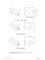
4.3. Pirani Sensor
Figure 4.3a shows a thin metal film resistive element on a one micron thick Si3N4 continuous membrane
surrounded by a thin film reference resistor on a Si substrate. The membrane is heated to a constant 8 °C above
ambient temperature that is monitored by the substrate resistor. The membrane resistor is approximately 60 Ω
and a constant substrate to membrane resistance ratio is maintained. Figure 4.3b shows the Pirani die in cross
section. A parallel Si lid is eutectically bonded to the Au pads and sits 5 microns above the membrane. As
shown, this dimension gives a Knudsen number of greater than 0.01 up to atmospheric pressure, which ensures
a molecular flow component. At 10 Torr the region above the membrane is totally in the molecular flow regime
and thus provides a relatively linear output verses pressure overlapping the linear output versus pressure of the
piezo.
The measurement technique is to produce an output signal that is proportional to the power supplied to the
heated resistor by using the product of the current and voltage. This rejects errors introduced by resistance
changes since the sensor resistance is no longer part of the power equation.
A signal proportional to the power is obtained by multiplying the voltage across the heated sensor and the
voltage impressed by the direct current across a constant series resistance. The power supplied to the sensor
resistor must equal the heat dissipated (Et). The three main heat loss routes from the heated sensor are thermal
conduction through the silicon nitride membrane to the silicon substrate (Es) radiation losses (Er) and thermal
conduction through the gas to the silicon substrate (Eg); thus, as shown in Figure 4.3b,
Et = Es + Er + Eg
The first term, Es, is dependent on the thermal conductivity of the silicon nitride (K), the temperature
difference (∆T) between the heater and silicon substrate and geometric factors (AM & L). ES is given by
Es = (K ∆T Am)/L
Am is the membrane cross sectional area through which the heat transfer occurs. This is, approximately, the
outer circumference of the membrane multiplied by the membrane thickness. L is the distance from the edge of
(Rs) the heated sensor resistor to the silicon substrate.
For any particular sensor, all of the factors, except ∆T, are constants dependent on its construction. The ∆T
is held constant by the control circuit. The thermal loss through the silicon nitride will be a constant value
independent of the thermal conductivity and pressure of the gas.
Radiation is another source of thermal losses. It can be determined from
Er = σε(Th4-Ta4)As
where
σ = Stefan-Boltzmann radiation constant
ε = thermal emissivity of the silicon nitride membrane
AS = surface area of the heated portion of the membrane
Th = temperature of Rs
Ta = ambient temperature
HPM-2002-OBEVacuum Gauge
Page 28 of 39
Figure 4.3a
Figure 4.3b
This radiation loss is also independent of the thermal conductivity of the gas. It is somewhat dependent
upon the absolute temperature of Rs and the ambient temperature, but since ∆T is kept to less than 20 °C, this
HPM-2002-OBEVacuum Gauge
Page 29 of 39
loss is only approximately 10% of Es. If ambient changes are small compared to the absolute values of the
temperature this loss can approximated as a constant with temperature.
Since the first two losses are essentially constant at high vacuum for a given sensor, we can measure these
losses and subtract them from the input power which leaves only the rate of heat transmission through the gas
(Eg).
In the viscous flow regime, the Eg loss is directly dependent on the thermal conductivity of the gas (Kg), the
surface area of the membrane, the differential temperature and is inversely proportional to distance between the
membrane and the lid. It can be written as
Eg = (Kg ∆T As)/∆x
The thermal conductivity of the gas is essentially constant when in viscous flow where the Knudsen number
(Kn) is less than 0.01. In the viscous flow regime there is no change in sensor output with pressure since all of
the losses are constants with pressure.
In the molecular flow regime where (Kn > 1) the thermal conductivity of the gas becomes directly
proportional to the gas pressure as shown below. We can expect then that Eg will be constant at high pressures
and directly proportional to the pressure at low pressures. The energy loss, Eg, changes between these two
controlling equations as the system passes through the transition region (0.01 < Kn < 1).
Eg = arLt(273/Th)1/2(Th-Ta)AgP
where
ar = accomodation coefficient
Lt = free molecule thermal conductivity
Th = temperature of heated membrane
Ta = ambient temperature
P = pressure
Ag = surface area of the heated portion of the membrane
For nitrogen at a pressure of 760 Torr and a temperature of 20 °C the mean free path (λ) is less than 1 x 10meters and is inversely proportional to pressure. Since the thermal transfer distance (∆x) is a few micrometers,
this sensor will remain in the molecular flow regime at a much higher pressure (10 Torr) than is typical for a
thermal vacuum gauge. This extends the linear response part of the output curve up into the 1 Torr range. The
nonlinear transition region will extend up to 1000 Torr.
7
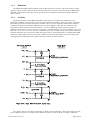
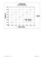
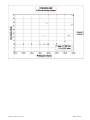
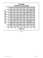
4.4. Dual Sensor Operation
The microprocessor in the control unit continuously monitors the outputs of both the piezoresistive sensor
and the Pirani sensor. Figure 4.4 shows representations of the sensors output over the pressure range from 10-5
Torr to 10+3 Torr. The microprocessor uses the output of the piezoresistive sensor at high pressures (>32
Torr) and uses the output of the Pirani sensor at low pressures (<8 Torr). In the crossover region, a software
averaging algorithm ensures a smooth transition between the two sensors.
HPM-2002-OBEVacuum Gauge
Page 30 of 39
Figure 4.4
HPM-2002-OBEVacuum Gauge
Page 31 of 39
5.
Troubleshooting
5.1. Advanced Setup Guide
The HPM-2002-OBE has several setup and control commands which can be accessed by using the
ADJUST rotary encoder and SELECT pushbutton and at the same time viewing the display. Note that most of
the commands, which are described below, can be accessed using equivalent RS232/485 commands.
The advanced setup is accessed from the Run mode. With the Run light illuminated (and not flashing),
each click of the ADJUST rotary encoder in the clockwise direction will advance the display through each
command. Once arriving at the desired command, the user can change the parameter (or initiate command) by
pressing the SELECT pushbutton. When finished with the advanced setup, the user may return to the normal
Run mode by turning the ADJUST counter-clockwise until the pressure is once again displayed. The
parameters are not stored upon leaving the command and entering the normal Run mode via ADJUST. To
make the changes permanent, the SAVE EEPROM command is used. Note that turning the ADJUST clockwise
indefinitely will simply cycle through the commands.
Normal Run
RS485 Address
Turnaround Delay
Decimation Ratio
Save EEPROM
Restore EEPROM
Restore Calibration
Restore Factory Defaults
CLOCKWISE
Data Bits/Parity Bits/Stop Bits
COUNTER-CLOCKWISE
Baud Rate
Software Reset
Normal Run
etc…
The following list gives a description of each of the commands listed above along with the syntax for the
equivalent RS232/485 command. See RS232/485 section for more details.
RS485 Address
A_01
Multipoint A_01, A_02, … A_FE, A_FF
The RS485 address is the multipoint address of the HPM-2002-OBE. If the unit is configured for RS232,
then this parameter must set to a value of E0 or greater.
(Valid multipoint range 01 to DF)
*{aa}A={aa}<CR>
HPM-2002-OBEVacuum Gauge
Page 32 of 39
Baud Rate
B_2.4
B_2.4, B_4.8, B_9.6, B_19.2, B_38.4, B_57.6, B_125, B_250, B_500
The baud rate is given in kbaud. For example, B_9.6 corresponds to a 9600 baud.
Note: There is no equivalent RS232/485 command.
Data Bits/Parity Bits/Stop Bits
P8n1
8n1, 8n2, 7n2, 7E1, 7E2, 7o1, 7o2, 701, 702, 711,712
The first character, “8” corresponds to the number of data bits. (e.g. 7 or 8).
Second character, “n” corresponds to the parity bit. (e.g. n- no parity, E- even parity, o- odd parity, 0space, 1- mark)
The last character, “1” corresponds to the number of stop bits. (e.g. 1 or 2)
Note: There is no equivalent RS232/485 command.
Turnaround Delay
dt06
dt00, dt01, ...dtFE, dtFF
The turnaround delay is unique to multipoint communications. It is the delay between receipt of an
incoming command to transmission of the response. Each increase in the hex value corresponds to an
increase in the delay time of approximately 8 ms.
*{aa}T={dd}<CR>
Decimation Ratio
dr5F
5F, 6F, …, FF
The decimation ratio can be used to set the amount of sampling which is performed by the HPM-2002OBE’s A/D converters. The higher the value of the hex number, the more sampling takes place before the
pressure reading is updated. More sampling leads to more stability of pressure readings particularly below 1
mTorr. However, the increased sampling increases the response time of the gauge to sudden pressure
changes.
D={dddd}<CR>
Save EEPROM
S_EE
Save EEPROM stores the calibration parameters which are in the HPM-2002-OBE’s CPU into the HPM2002-OBE’s CPU board’s EEPROM. The CPU board’s EEPROM is not the HPM-2002s tube EEPROM.
The CPU board EEPROM stores the gauge setup (baud rate, parity, address, set points, gas selection, etc.).
The HPM-2002s tube EEPROM stores the tube’s calibration parameters.
EEW<CR>
Restore EEPROM
r_EE
Restore EEPROM transfers the setup from the HPM-2002-OBE’s CPU board’s EEPROM into the HPM2002-OBE’s CPU.
EER<CR>
HPM-2002-OBEVacuum Gauge
Page 33 of 39
Restore Calibration
r_CL
Restore Calibration transfers the calibration from the HPM-2002s tube EEPROM into the HPM-2002OBE’s CPU.
EEI<CR>
Restore Factory Defaults
r_Fd
The Restore Factory Default command is used to place calibration parameters into the CPU. From this
point the gauge can be calibrated. After calibration, the calibration parameters are stored in the HPM-2002s
tube’s EEPROM.
/#<CR>
Software Reset
rrrr
This command performs a complete reboot of the HPM-2002-OBE. The CPU is reset and the tube’s
calibration parameters are loaded.
/r<CR>
5.2. Frequently Asked Questions
Why does my display read, “Err1”?
This message indicates that an error has occurred during transfer of data between the HPM-2002-OBE’s
CPU and the sensor tube’s EEPROM where the calibration coefficients are stored. If this error occurs during
initial startup, then the factory default calibration coefficients will be automatically loaded. The factory
defaults are often not accurate (typically ±50% or greater), however they allow the user to calibrate the
gauge. If the sensor tube’s EEPROM cannot communicate with the CPU, then any new calibration will be
lost when the gauge power is disconnected.
Sensor tube EEPROM performance can be verified by use of the RESTORE FACTORY DEFAULTS and
the RESTORE CALIBRATION commands in the following manner. After calibration, use the RESTORE
FACTORY DEFAULTS command. The pressure reading will shift dramatically. Immediately use the
RESTORE CALIBRATION command. The pressure reading will return to the calibration value if the tube
EEPROM communication is working properly. See the advanced setup guide (Section 5.1) for more
information.
Why does my display read, “Err2”?
This message indicates that an error has occurred in the CPU’s EEPROM where the set points, gas number,
and communication port settings are stored. If this error occurs during initial startup, then the factory default
values for these settings will be in effect. CPU EEPROM performance can be verified by use of the
RESTORE EEPROM command. See the advanced setup guide (Section 5.1) for more information.
Caution: Use of the SAVE EEPROM command at this time will overwrite all previously stored values with
default values.
Note: An “Err2” message is a exceedingly rare occurrence. If this error occurs then the CPU’s EEPROM is
most likely defective.
Why does my display read, “Err4”?
This message indicates that a communications error has occurred between the HPM-2002-OBE and a data
acquisition computer. This error is associated with the serial interface (RS232/485) and can indicate a baud
rate or parity mismatch, a framing error or an overrun condition. The error can also occur if the data
acquisition computer is powered down while the HPM-2002-OBE is still connected.
Modifying as necessary the baud rate, parity, word length and/or the stop bits on either the data acquisition
computer or the HPM-2002-OBE, usually eliminates this error. Many operating systems are shipped with a
HPM-2002-OBEVacuum Gauge
Page 34 of 39
communications program (e.g. WindowsÔ Hyperterminal) which can be used to communicate with RS232
versions of the HPM-2002-OBE. The Transmit Device Status (“S<CR>”) command will retrieve the
HPM-2002-OBE’s status register. A successful read of the status register will clear the “Err4” condition.
What are Err3, Err5, Err6 and Err7?
These are simultaneous error conditions, i.e. Err3 = Err1+Err2.
Why does my display read, “U.U”?
“U.U” stands for unconnected piezo/unconnected Pirani. This message indicates that the voltage readings
from the sensors are outside any usable range. Most often this occurs when there is no sensor tube connected
to the HPM-2002-OBE. This error will also occur if there is a problem with the user’s DC power supply.
Verify that the voltage supplied to the HPM-2002-OBE is within the specified range using a voltmeter at
pins 3 and 4 on the power cable. After power verification and with the voltage still applied, hot plug the cable
into the HPM-2002-OBE. If the “U.U” still appears, most likely the sensor tube (HPM-2002s) needs to be
replaced.
Why does my display read, “U .”?
“U.” stands for unconnected piezo. This message indicates that the voltage reading from the piezoresistive
sensor is outside any usable range. While this message can mean that the sensor tube (HPM-2002s) will
need to be replaced, it can also indicate that the piezo zero calibration parameter, which is stored in the
sensor tube’s EEPROM, has become corrupted or lost. (See next FAQ)
Why does my display temporarily show, “U .” as I pump the system down?
“U .” stands for unconnected piezo. This message may flash near the dual sensor crossover pressure range if
the piezo zero calibration parameter has been corrupted or lost.
The RESTORE CALIBRATION command will download the calibration parameters from the HPM-2002OBE to the sensor tube. See the advanced setup guide (Section 5.1) for more information. If the error
persists at the crossover point, then a calibration of the Piezo sensor should be performed. The Piezo Zero is
updated when the Pirani pressure is less than 125 mTorr. In order to update and save the Piezo Zero
parameter:
•
•
•
•
Pump out to 100 mTorr or less
Using SELECT, step to the CAL function
Rotate ADJUST one step in either direction and then back to its original position (CAL light starts
flashing)
Using SELECT, exit the CAL function and return to the Run mode
Changing the Piezo Zero will shift the atmospheric reading by the same amount. therefor the atmospheric
readong should also be checked and re-adjusted if necessary.
Why does my display read, “. U”?
This message indicates that the voltage readings from the thin film Pirani sensor are outside any usable
range. This usually indicates that the sensor is defective and will need to be replaced.
HPM-2002-OBEVacuum Gauge
Page 35 of 39
6. WARRANTY
6.1. Warranty Repair Policy
Hastings Instruments warrants this product for a period of one year from the date of shipment to be free
from defects in material and workmanship. This warranty does not apply to defects or failures resulting from
unauthorized modification, misuse or mishandling of the product. This warranty does not apply to batteries
or other expendable parts, or to damage caused by leaking batteries or any similar occurrence. This warranty
does not apply to any instrument which has had a tamper seal removed or broken.
This warranty is in lieu of all other warranties, expressed or implied, including any implied warranty as to
fitness for a particular use. Hastings Instruments shall not be liable for any indirect or consequential
damages.
Hastings Instruments, will, at its option, repair, replace or refund the selling price of the product if Hastings
Instruments determines, in good faith, that it is defective in materials or workmanship during the warranty
period. Defective instruments should be returned to Hastings Instruments, shipment prepaid, together with a
written statement of the problem and a Return Material Authorization (RMA) number.
Please consult the factory for your RMA number before returning any product for repair. Collect freight will
not be accepted.
6.2. Non-Warranty Repair Policy
Any product returned for a non-warranty repair must be accompanied by a purchase order, RMA form and
a written description of the problem with the instrument. If the repair cost is higher, you will be contacted for
authorization before we proceed with any repairs. If you then choose not to have the product repaired, a
minimum will be charged to cover the processing and inspection. Please consult the factory for your RMA
number before returning any product repair.
TELEDYNE HASTINGS INSTRUMENTS
804 NEWCOMBE AVENUE
HAMPTON, VIRGINIA 23669 U.S.A.
ATTENTION: REPAIR DEPARTMENT
TELEPHONE
TOLL FREE
FAX
E MAIL
INTERNET
(757) 723-6531
1-800-950-2468
(757) 723-3925
[email protected]
http://www.teledyne-hi.com
Repair Forms may be obtained from the “Information Request” section of the Hastings Instruments web
site.
HPM-2002-OBEVacuum Gauge
Page 36 of 39
7.
Diagrams and Drawings
HPM-2002-OBEVacuum Gauge
Page 37 of 39
HPM-2002-OBEVacuum Gauge
Page 38 of 39
HPM-2002-OBEVacuum Gauge
Page 39 of 39