1
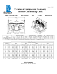
March 16, 2011 Tecumseh Compressor Company Indoor Condensing Units Model: AWA2457ZXTXF BoM: 2B3264-1 R-404A 1.5 HP AIRCOOLED Dimensions, inches Line Connection* Pumpdown Air L W H CH Suction Liquid 90 F 90% SCFM 25.0 33.5 19.5 14.7 7/8” S 3/8” S 16.46 lbs 1600 AWA2457ZXTXF * F = Flare, S = Solder, RF or RS = Rotolock with Flare or Solder Connections, C = Compression Fitting Model Oil Ch Oz. 38.5 Gr. Wt. Lbs. 200 Ambient Temperatures Evaporator T 80F Watts 90F Cond T BTUH Watts 100F °F PSIG BTUH Cond T BTUH -40 11.9 1965 941 85 1501 879 94 -35 15.0 2550 1027 86 1992 970 96 -30 10.7 3263 1123 87 2608 1073 -25 14.0 4040 1220 88 3295 1178 -20 17.1 4921 1320 89 4086 1288 -15 19.3 5882 1422 91 4955 -10 24.5 6924 1525 93 5895 110F Watts Cond T BTUH Watts Cond T --- --- --- --- --- --- --- --- --- --- --- --- 96 1946 1016 105 1285 955 114 97 2564 1127 106 1813 1070 115 98 3275 1246 107 2447 1193 116 1401 99 4032 1366 108 3137 1321 117 1515 101 4883 1490 110 3863 1452 118 -5 28.8 8059 1629 95 6932 1632 103 5797 1617 111 4743 1589 119 0 33.5 9323 1732 97 8037 1749 105 6814 1746 113 5591 1726 121 5 36.5 10537 1836 98 9195 1866 106 7897 1875 114 6556 1866 122 10 43.7 11976 1932 100 10462 1980 108 9028 2003 116 7615 2006 124 60 Hz Performance Return gas temp. 40F, 5F sub-cooling March 16, 2011 Specifications/ Parts: Model Unit Bill of Material Nominal Volts-Hz-Ph Refrigeration Range Design Pressure Low Design Pressure High Voltage Range Min. Circuit Ampacity Max. Fuse Size (amps) Compressor Model Comp. Bill of Material Compressor RLA/LRA Overload Relay Run Capacitor Run Capacitor Rating Start Capacitor Start Capacitor Rating Contactor Unit Drawing Wiring Diagram AWA2457ZXTXF 2B3264-1 200-230-60-3 -40° to 10°F 181 450 180 to 254 8.9 15 AWA2450ZXT AW615RT-120-A2 5.8 / 40.5 INTERNAL N/A N/A N/A N/A N/A 91014 DGU1918-59 91263-05 Fan Motor Fan Motor RLA Fan Blade Fan Guard Fan Shroud High Pressure Switch Low Pressure Control Oil Separator * Condenser Fan Switch Fan Switch Receiver Tank Liquid Valve Liquid Filter * Sight Glass * Suction Valve * Rotolock Valve Gasket Discharge Valve Suction Filter * Accumulator * Crankcase Heater Defrost Timer * Suction Shut Off Valve* Liquid Shut Off Valve* Shrader Valve Body* Valve Core* * = Equipped Units Only Electrical Diagram 810F050C20 (2) 0.7 Each 51568-1 (2) 70831 (2) 70648-2 84095-2 84026-2 704-00002 50855-1 84096-1 84096-2 51082-1 31592 70081 70084 31529-1 30233 56596 70082 TK00042000 91022-1 84110 56500-K14 56500-K06 56510 56552