1
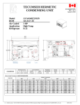
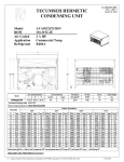
March 16, 2011 Tecumseh Compressor Company Indoor Condensing Units Model: AVA2515ZXTXF BoM: 2B3265-1 R-404A 3.75 HP AIRCOOLED Dimensions, inches Line Connection* Pumpdown Air L W H CH Suction Liquid 90 F 90% SCFM 25.0 33.5 19.5 16.0 7/8” S 3/8” S 18.14 lbs 1550 AVA2515ZXTXF * F = Flare, S = Solder, RF or RS = Rotolock with Flare or Solder Connections, C = Compression Fitting Model Oil Ch Oz. 38.5 Gr. Wt. Lbs. 230 Ambient Temperatures Evaporator T 80F 90F °F PSIG BTUH Watts Cond T BTUH Watts -40 34.2 6415 2161 89 5259 -35 36.8 8006 2394 90 6868 100F 110F Cond T BTUH Watts Cond T BTUH Watts Cond T 2063 99 2341 1007 52 --- --- --- 2324 100 5489 2236 109 4202 2139 118 -30 39.6 9689 2639 91 8529 2594 101 7069 2523 111 5599 2431 119 -25 43.1 11463 2894 93 10242 2872 103 8685 2820 112 7035 2736 121 -20 46.1 13330 3159 95 12007 3158 104 10336 3125 114 8510 3053 122 -15 49.9 15288 3435 97 13824 3454 106 12022 3440 115 10024 3381 124 -10 53.7 17338 3722 99 15694 3758 108 13744 3762 117 11578 3722 126 0 62.8 21715 4328 103 19589 4392 113 17293 4434 121 14803 4439 130 5 68.05 24041 4646 106 21615 4722 115 19120 4783 124 16474 4815 132 10 73.3 26459 4976 109 23693 5061 118 20982 5141 126 18184 5204 134 60 Hz Performance Return gas temp. 40F, 5F sub-cooling March 16, 2011 Specifications/ Parts: Model Unit Bill of Material Nominal Volts-Hz-Ph Refrigeration Range Design Pressure Low Design Pressure High Voltage Range Min. Circuit Ampacity Max. Fuse Size (amps) Compressor Model Comp. Bill of Material Compressor RLA/LRA Overload Relay Run Capacitor Run Capacitor Rating Start Capacitor Start Capacitor Rating Contactor Unit Drawing Wiring Diagram AVA2515ZXTXF 2B3265-1 200-230-60-3 -40° to 10°F 181 450 180 to 254 15.3 25 AVA2512ZXT AV180RT-012-P2 11.0 / 65.1 INTERNAL N/A N/A N/A N/A N/A 91014 DGU1920-39 91263-05 Fan Motor Fan Motor RLA Fan Blade Fan Guard Fan Shroud High Pressure Switch Low Pressure Control Oil Separator * Condenser Fan Switch Fan Switch Receiver Tank Liquid Valve Liquid Filter * Sight Glass * Suction Valve * Rotolock Valve Gasket Discharge Valve Suction Filter * Accumulator * Crankcase Heater Defrost Timer * Suction Shut Off Valve* Liquid Shut Off Valve* Shrader Valve Body* Valve Core* Defrost Timer * Electrical Diagram 810F050C20 (2) 0.7 Each 51568-1 (2) 70831 (2) 70648-2 84095-2 84026-2 704-00002 50858-1 84096-1 84096-2 51082-1 31592 70081 70084 31529-1 30233 56596 70082 TK00042000 90699 84110 56500-K14 56500-K06 56510 56552 84110