1
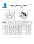
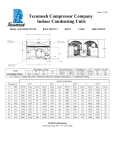
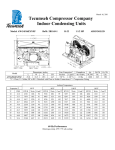
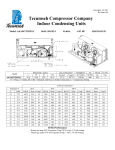
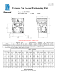
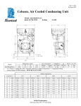
March 16, 2011 Tecumseh Compressor Company Indoor Condensing Units Model: AWA9511ZXNXF BoM: 2B1167-1 R-404A 1.5 HP AIRCOOLED Dimensions, inches Line Connection* Pumpdown Air L W H CH Suction Liquid 90 F 90% SCFM 25.0 33.5 19.5 14.7 7/8” S 3/8” S 16.46 lbs 1850 AWA9511ZXNXF * F = Flare, S = Solder, RF or RS = Rotolock with Flare or Solder Connections, C = Compression Fitting Model Oil Ch Oz. 38.5 Gr. Wt. Lbs. 190 Ambient Temperatures Evaporator T °F PSIG 80F BTUH Watts 90F Cond T 100F 110F BTUH Watts Cond T BTUH Watts Cond T BTUH Watts Cond T -5 28.1 5986 1514 98 5482 1501 103 4711 1481 110 3659 1455 119 0 32.8 6872 1614 100 6366 1603 104 5555 1587 111 4386 1567 120 5 37.9 7890 1714 101 7367 1705 106 6501 1693 112 5210 1681 121 10 43.3 9036 1811 103 8482 1805 107 7549 1799 114 6133 1796 123 15 49.1 10314 1908 104 9714 1906 109 8699 1906 115 7153 1911 124 20 55.5 11723 2004 106 11062 2006 110 9951 2013 117 8272 2028 126 25 62.2 13261 2099 108 12525 2106 112 11306 2120 119 9488 2145 128 30 69.5 14930 2192 110 14104 2205 114 12762 2227 121 10803 2263 129 35 77.2 16730 2285 112 15799 2303 116 14321 2334 122 12216 2382 131 40 85.5 18661 2376 114 17610 2401 118 15982 2442 124 13726 2502 133 45 94.3 20721 2466 116 19536 2498 120 17745 2550 126 15335 2623 135 60 Hz Performance Return gas temp. 40F Evaporator Temp. 20F or less, 5F sub-cooling Return gas temp. 65F for Evaporator Temp. > 20F, 5F sub-cooling March 16, 2011 Specifications/ Parts: Model Unit Bill of Material Nominal Volts-Hz-Ph Refrigeration Range Design Pressure Low Design Pressure High Voltage Range Min. Circuit Ampacity Max. Fuse Size (amps) Compressor Model Comp. Bill of Material Compressor RLA/LRA Overload Relay Run Capacitor Run Capacitor Rating Start Capacitor Start Capacitor Rating Contactor Unit Drawing Wiring Diagram AWA9511ZXNXF 2B1167-1 208-230-60-1 -5° to 45°F 181 450 187 to 254 14.9 25 AWA9490ZXN AW616ET-099-P2 10.6 / 51.0 INTERNAL 820ARR3H23 85PR370F17 35MFD 370V(M)VDE 85PS330D17 145-175 MFD 330V VDE 91014 DGU1918-58 91263-02 Fan Motor Fan Motor RLA Fan Blade Fan Guard Fan Shroud High Pressure Switch Low Pressure Control Oil Separator * Condenser Fan Switch Fan Switch Receiver Tank Liquid Valve Liquid Filter * Sight Glass * Suction Valve * Rotolock Valve Gasket Discharge Valve Suction Filter * Accumulator * Crankcase Heater Defrost Timer * Suction Shut Off Valve* Liquid Shut Off Valve* Shrader Valve Body* Valve Core* * = Equipped Units Only Electrical Diagram 810F050C20 (2) 0.7 Each 51568-1 (2) 70831 (2) 70648-2 84095-2 84026-2 704-00002 50855-1 84096-1 84096-2 51082-1 31592 70081 70084 31529-1 30233 56596 70082 TK00042000 91022-1 N/A 56500-K14 56500-K06 56510 56552