1
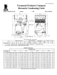
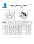
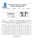
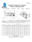
March 16, 2011 Tecumseh Compressor Company Indoor Condensing Units Model: AWA2457ZXDXF BoM: 2B3263-1 R-404A 1.5 HP AIRCOOLED Dimensions, inches Line Connection* Pumpdown Air L W H CH Suction Liquid 90 F 90% SCFM 25.0 33.5 19.5 14.7 7/8” S 3/8” S 16.46 lbs 1600 AWA2457ZXDXF * F = Flare, S = Solder, RF or RS = Rotolock with Flare or Solder Connections, C = Compression Fitting Model Oil Ch Oz. 38.5 Gr. Wt. Lbs. 200 Ambient Temperatures Evaporator T 80F °F PSIG BTUH -40 11.9 -35 15.0 -30 -25 90F 100F 110F Watts Cond T BTUH Watts Cond T BTUH Watts Cond T BTUH Watts Cond T 1960 954 2549 1045 85 1501 894 94 --- --- --- --- --- --- 86 1985 986 95 --- --- --- --- --- --- 10.7 3263 14.0 4039 1143 87 2607 1092 96 1949 1034 105 1284 971 114 1241 88 3294 1199 97 2560 1147 106 1814 1089 115 -20 17.1 4920 1343 89 4085 1311 98 3275 1268 107 2435 1214 116 -15 -10 19.3 5880 1448 91 4953 1426 99 4031 1391 108 3137 1345 117 24.5 6921 1553 93 5893 1543 101 4881 1518 110 3850 1478 118 -5 28.8 8056 1660 95 6929 1662 103 5794 1647 111 4697 1617 119 0 33.5 9320 1764 97 8095 1781 105 6810 1778 113 5588 1758 121 5 36.5 10531 1870 98 9189 1901 106 7892 1910 114 6552 1901 122 10 43.7 11970 1969 100 10460 2018 108 9022 2041 116 7609 2044 124 60 Hz Performance Return gas temp. 40F. 5F sub-cooling March 16, 2011 Specifications/ Parts: Model Unit Bill of Material Nominal Volts-Hz-Ph Refrigeration Range Design Pressure Low Design Pressure High Voltage Range Min. Circuit Ampacity Max. Fuse Size (amps) Compressor Model Comp. Bill of Material Compressor RLA/LRA Overload Relay Run Capacitor Run Capacitor Rating Start Capacitor Start Capacitor Rating Contactor Unit Drawing Wiring Diagram AWA2457ZXDXF 2B3263-1 208-230-60-1 -40° to 10°F 181 450 187 to 254 13.4 20 AWA2450ZXD AW615ET-099-A2 9.4 / 56.0 INTERNAL 820ARR3H23 85PR370F23 30MFD 370V(M)VDE 85PS330D16 130-156 MFD 330V VDE 91014 DGU1918-59 91263-04 Fan Motor Fan Motor RLA Fan Blade Fan Guard Fan Shroud High Pressure Switch Low Pressure Control Oil Separator * Condenser Fan Switch Fan Switch Receiver Tank Liquid Valve Liquid Filter * Sight Glass * Suction Valve * Rotolock Valve Gasket Discharge Valve Suction Filter * Accumulator * Crankcase Heater Defrost Timer * Suction Shut Off Valve* Liquid Shut Off Valve* Shrader Valve Body* Valve Core* * = Equipped Units Only Electrical Diagram 810F050C20 (2) 0.7 Each 51568-1 (2) 70831 (2) 70648-2 84095-2 84026-2 704-00002 50855-1 84096-1 84096-2 51082-1 31592 70081 70084 31529-1 30233 56596 70082 TK00042000 91022-1 84110 56500-K14 56500-K06 56510 56552