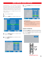
1
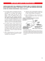
Model No:
DP50747
If you need additional assistance?
Call toll free 1.800.877.5032
We can Help!
Owner’s Manual
Table of Contents . . . . . . . . . . . 5
Frequent Asked
Questions (FAQ) . . . . . . . . . . . 47
© 2007 Sanyo Manufacturing Corporation
CAUTION
RISK OF ELECTRIC SHOCK DO NOT OPEN
CAUTION: TO REDUCE THE RISK OF ELECTRIC SHOCK, DO NOT REMOVE COVER (OR
BACK). NO USER-SERVICEABLE PARTS INSIDE. REFER SERVICING TO QUALIFIED
SERVICE PERSONNEL.
THIS SYMBOL INDICATES THAT DANGEROUS VOLTAGE CONSTITUTING A RISK OF ELECTRIC SHOCK IS PRESENT WITHIN THIS UNIT.
THIS SYMBOL INDICATES THAT THERE ARE IMPORTANT OPERATING
AND MAINTENANCE INSTRUCTIONS IN THE LITERATURE ACCOMPANYING THIS UNIT.
WARNING: TO REDUCE THE RISK OF FIRE OR ELECTRIC SHOCK, DO NOT EXPOSE THIS APPLIANCE TO RAIN
OR MOISTURE.
IMPORTANT SAFETY INSTRUCTIONS
CAUTION: PLEASE ADHERE TO ALL WARNINGS ON THE PRODUCT AND IN THE OPERATING INSTRUCTIONS.
BEFORE OPERATING THE PRODUCT, PLEASE READ ALL OF THE SAFETY AND OPERATING INSTRUCTIONS.
RETAIN THIS LITERATURE FOR REFERENCE. Follow all instructions...
1. Read these instructions.
2. Keep these instructions.
3. Heed all warnings.
4. Follow all instructions.
12. Use only with the cart, stand, tripod, bracket, or
table specified by the manufacturer, or sold with
the apparatus. When a cart is used, use caution
when moving the cart/apparatus combination to
avoid injury from tip-over.
5. Do not use this apparatus near water.
6. Clean only with dry cloth.
7. Do not block any ventilation openings. Install
in accordance with the manufacturer’s
instructions.
8. Do not install near any heat sources such as
radiators, heat registers, stoves, or other apparatus (including amplifiers) that produce heat.
9. Do not defeat the safety purpose of the polarized
or grounding-type plug. A polarized plug has
two blades with one wider than the other. A
grounding-type plug has two blades and a third
grounding prong. The wide blade or the third
prong are provided for your safety. If the provided plug does not fit fully into your outlet,
consult an electrician for replacement of the
obsolete outlet.
10. Protect the power cord from being walked on or
pinched particularly at plugs, convenience
receptacles, and the point where they exit from
the apparatus.
11. Only use attachments/accessories specified by
the manufacturer.
13. Unplug this apparatus during lightning storms
or when unused for long periods of time.
14. Refer all servicing to qualified service personnel.
Servicing is required when the apparatus has
been damaged in any way, such as powersupply cord or plug is damaged, liquid has been
spilled or objects have fallen into the apparatus,
the apparatus has been exposed to rain or moisture, does not operate normally, or has been
dropped.
(CONTINUED ON NEXT PAGE.)
2
IMPORTANT SAFETY INSTRUCTIONS
CAUTION: PLEASE ADHERE TO ALL WARNINGS ON THE PRODUCT AND IN THE OPERATING INSTRUCTIONS.
BEFORE OPERATING THE PRODUCT, PLEASE READ ALL OF THE SAFETY AND OPERATING INSTRUCTIONS.
RETAIN THIS LITERATURE FOR REFERENCE. Follow all instructions...
15. If an outside antenna is connected to the television equipment, be sure the antenna system is
grounded so as to provide some protection
against voltage surges and built up static
charges. In the U.S. Selection 810-21 of the
National Electrical Code provides information
with respect to proper grounding of the mast
and supporting structure, grounding of the leadin wire to an antenna discharge unit, size of
grounding conductors, location of antenna discharge unit, connection to grounding electrodes,
and requirements for the grounding electrodes.
16. An outside antenna system should not be
located in the vicinity of overhead power lines or
other electrical light or power circuits, or where
it can fall into such power lines or circuits. When
installing an outside antenna system, extreme
care should be taken to keep from touching such
power lines or circuits as contact with them
might be fatal.
17. Wall or Ceiling Mounting—The product should
be mounted to a wall or ceiling only as recommended by the manufacturer.
18. "Apparatus shall not be exposed to dripping or
splashing and no objects filled with liquids, such
as vases, shall be placed on the apparatus."
19. When the MAINS plug is used as the disconnect
device, the disconnect device shall remain
readily operable.
EXAMPLE OF ANTENNA GROUNDING ACCORDING
TO NATIONAL ELECTRICAL CODE,
ANSI/NFPA 70
“Note to CATV system installer:
This reminder is provided to call the CATV system installer’s attention to
Article 820-40 of the NEC that provides guidelines for proper grounding
and, in particular, specifies that the cable ground shall be connected to
the grounding system of the building, as close to the point of cable entry
as practical.”
3
TO THE OWNER
Welcome to the World of Sanyo
Thank you for purchasing this Sanyo High-Definition Digital Plasma Television.
You made an excellent choice for Performance, Reliability, Features, Value, and
Styling.
Important Information
Before installing and operating this DTV, read this manual thoroughly. This DTV
provides many convenient features and functions. Operating the DTV properly
enables you to manage those features and maintain it in good condition for many
years to come.
If your DTV seems to operate improperly, read this manual again, check
operations and cable connections and try the solutions in the “Helpful Hints”
sections of this manual.
If the problem still persists, please call
1-800-877-5032. We can help!
“Note to CATV system installer:
This reminder is provided to call the CATV system installer’s attention to
Article 820-40 of the NEC that provides guidelines for proper grounding
and, in particular, specifies that the cable ground shall be connected to
the grounding system of the building, as close to the point of cable entry
as practical.”
PROTECTING THE PLASMA SCREEN
The screen is likely to be damaged if it is
not maintained properly. Do not use hard
objects such as hard cloth or paper. Do not
use excessive pressure when cleaning the screen;
excessive pressure can cause permanent discoloration or dark spots.
NEVER spray liquids on the screen.
4
CONTENTS
TO THE OWNER . . . . . . . . . . . . . . . . . . . . . . . . . . . . . . 2
IMPORTANT SAFETY INSTRUCTIONS . . . . . . . . . . . . . 3 ~ 4
PROTECTING THE PLASMA SCREEN . . . . . . . . . . . . . . . . 4
FEATURES . . . . . . . . . . . . . . . . . . . . . . . . . . . . . . . . . . 6
SPECIFICATIONS . . . . . . . . . . . . . . . . . . . . . . . . . . . . . . 7
HANDLING PRECAUTIONS . . . . . . . . . . . . . . . . . . . . . . . .8
POSITIONING PRECAUTIONS . . . . . . . . . . . . . . . . . . . . . 8
REMOVING THE PLASMA STAND (OPTIONAL) . . . . . . . . . .9
WALL MOUNTING (OPTIONAL) . . . . . . . . . . . . . . . . . . . .9
HDTV BACK RIGHT SIDE PANEL—JACKS LOCATIONS
& FUNCTIONS . . . . . . . . . . . . . . . . . . . . . . . . . . . . . . . 10
HDTV BACK SIDE PANEL—JACKS LOCATIONS
& FUNCTIONS . . . . . . . . . . . . . . . . . . . . . . . . . . . 11 ~ 12
GLOSSARY OF CABLES . . . . . . . . . . . . . . . . . . . . . . . . 13
CHOOSE YOUR CONNECTION . . . . . . . . . . . . . . . . . . . . 14
GETTING STARTED (REQUIRED INITIAL SETUP) . . . . . . . . 15
Installing two “AA” Batteries . . . . . . . . . . . . . . . . . . . . . . . 15
Initial Signal Connections Integrated Digital (DTV) /
Analog (RF) Antenna Connection . . . . . . . . . . . . . . . . . . . 15
Connecting AC Power Cord . . . . . . . . . . . . . . . . . . . . . . . . 16
All Channel Search . . . . . . . . . . . . . . . . . . . . . . . . . . . . . . 17
DIGITAL AV CONNECTIONS
HDMI CONNECTIONS
OPTION 1: Connect a DVD Player or Game System . . . . . 18
Helpful Hints for HDMI Input 2/3 connections . . . . . . 18
OPTION 2: Connect a Set-Top (STB) to DVI . . . . . . . . . . . 19
Helpful Hints for HDMI Input 1 connections . . . . . . . . 19
VIDEO2 / VIDEO3 Component Jacks
OPTION 1: Connect a Set-Top (STB) . . . . . . . . . . . . . . . . . 20
Helpful Hints for Video2/3 connections . . . . . . . . . . . . 20
OPTION 2: Connect a DVD Player . . . . . . . . . . . . . . . . . . 21
Helpful Hints for Video2/3 connections . . . . . . . . . . . 21
OPTION 3: Connect a Game System . . . . . . . . . . . . . . . . . 22
Helpful Hints for Video2/3 connections . . . . . . . . . . . 22
ANALOG AV CONNECTIONS
VIDEO1 COMPOSITE JACKS
OPTION 1: Connect Analog Cable, Cable Box, VCR,
and an Antenna . . . . . . . . . . . . . . . . . . . . . . . . . . . . . . . . 23
Helpful Hints for Video1 connections . . . . . . . . . . . . . 23
OPTION 2: Connect Analog Cable, VCR, and an Antenna . . 24
Helpful Hints for Video1 connections . . . . . . . . . . . . . 24
OPTION 3: Connect a DVD Player . . . . . . . . . . . . . . . . . . . 25
Helpful Hints for Video1 connections . . . . . . . . . . . . . 25
AUDIO CONNECTIONS
Connecting an AV Receiver . . . . . . . . . . . . . . . . . . . . . . . 26
Helpful Hints for Digital Audio Out connections . . . . . 26
Connecting a Stereo Amplifier . . . . . . . . . . . . . . . . . . . . . . 27
Helpful Hints for Analog Audio Out connections . . . . . 27
USING THE REMOTE CONTROL
Remote Control Keys (functions) . . . . . . . . . . . . . . . 28 ~ 31
Helpful Hints for Remote Control . . . . . . . . . . . . . . . . 31
MENU OPTIONS
How to Operate the On-Screen Menu . . . . . . . . . . . . . . . . 32
Menu Navigation Map . . . . . . . . . . . . . . . . . . . . . . . . . . . . 32
DTV ADJUSTMENT AND SETUP
All Channel Search . . . . . . . . . . . . . . . . . . . . . . . . . . . . . . 33
Digital Cable Search (Optional) . . . . . . . . . . . . . . . . . . . . . 34
Helpful Hints for Digital Cable Search . . . . . . . . . . . . . 34
Digital Add-On Search . . . . . . . . . . . . . . . . . . . . . . . . . . . . 35
Helpful Hints for Digital Add-On Search . . . . . . . . . . . 35
Analog Antenna Signal (Optional) . . . . . . . . . . . . . . . . . . . 36
Helpful Hints for Analog Antenna Signal . . . . . . . . . . . 36
Channel Scan Memory: Deleting Channels . . . . . . . . . . . . 37
Helpful Hints for Channel Scan Memory . . . . . . . . . . 37
Channel Scan Memory: Adding Channels . . . . . . . . . . . . . 38
Helpful Hints for Channel Scan Memory . . . . . . . . . . 38
Digital Caption . . . . . . . . . . . . . . . . . . . . . . . . . . . . . . . . . . 39
Changing the Look of Digital Captioning . . . . . . . . . . . 39
To View Captions . . . . . . . . . . . . . . . . . . . . . . . . . . . . . 40
Helpful Hints for Digital Caption . . . . . . . . . . . . . . . . . 40
V-Guide (Parental Control) . . . . . . . . . . . . . . . . . . . . . . . . 41
To Block MPAA Movie or TV Programs . . . . . . . . . . . . 41
To Setup V-Guide Ratings . . . . . . . . . . . . . . . . . . . . . . 41
On-Screen View of Blocked TV program . . . . . . . . . . . 42
To Temporarily Unblock MPAA Movie or TV Rating . . 42
To Unblock All MPAA Movie or All TV Rating . . . . . . . 42
TV Ratings (Age and Content-Based)
Symbol Explanation . . . . . . . . . . . . . . . . . . . . . . . . . . . . . 43
MPAA Movie Ratings (Age-Based)
Symbol Explanation . . . . . . . . . . . . . . . . . . . . . . . . . . . . . 43
Picture/Sound Adjustment . . . . . . . . . . . . . . . . . . . . 44 ~ 45
Helpful Hints for Picture/Sound . . . . . . . . . . . . . . . . . 45
Menu Language . . . . . . . . . . . . . . . . . . . . . . . . . . . . . . . . 46
Energy (Power) Saver . . . . . . . . . . . . . . . . . . . . . . . . . . . . 47
Picture Rotation (Screen Saver) . . . . . . . . . . . . . . . . . . . . 48
White Pattern (Panel Repair) . . . . . . . . . . . . . . . . . . . . . . . 49
GLOSSARY OF TERMS . . . . . . . . . . . . . . . . . . . . . . . . . 50
FAQ (FREQUENTLY ASKED QUESTIONS) . . . . . . . . . . . . . 51
WARRANTY . . . . . . . . . . . . . . . . . . . . . . . . . . . . . . . . 52
5
FEATURES
50" Plasma HDTV
Channel Scan Memory
Detachable Stand
Receives 181 Analog Channels (VHF 2~13 and
Trilingual Menu Options (English, Spanish, or
Channels
French)
Integrated Digital/Analog Tuner
XDS (Extended Data Services) displays station
call letters, title of show, and ratings when
broadcast
Energy Saver Mode
Screen Savers:
UHF 14~69; Cable 14~125); and 99 Digital
White Pattern
Picture Rotation
Sleep Timer (3 hours)
32-Key Remote Control
Automatic Channel Search
3-D Y/C Comb Filter
V-Chip for Movies and TV guidelines rating
limits (parental control)
Closed-Captioning: Analog EIA-608
Digital EIA-708
Audio Modes:
Digital—Main and Sub
Analog—Stereo, Mono,
and SAP
TERMINAL and CONNECTORS:
RF Antenna Input Jack: Digital and Analog
HDMI (Three sets) (with HDCP, and one
DVI Connection
Component Video (Y-Pb-Pr) Input (Two Sets)
S-Video Input
Front speakers (two): 6 x 12 cm
Rear Composite AV Input Jacks
Factory preset adjustments for picture/sound:
Coaxial Digital Audio Out
Auto, Manual with Tone Control
Picture Shape: PIX1 ~ PIX4
Fixed Audio (Left/Right) Out
Service Port
Audio Format: Dolby® Digital for ATSC (DTV)
and Analog for NTSC
Receivable Formats: Digital Tuner for ATSC
terrestrial broadcasts and nonscrambled
(ClearQAM) cable channels.
NTSC analog tuner for VHF/UHF or CATV
6
SPECIFICATIONS
SCREEN SIZE:
50" Wide Screen (Measured
Diagonally)
Weight:
SCANNING FORMAT:
720p (All Signals are
Converted to 720p)
Specifications are subject to change without notice.
RESOLUTION:
1365 x 768 (WXGA)
RF ANTENNA INPUT:
75 ohm—Digital/Analog
POWER REQUIREMENT:
Source: AC 120V, 60Hz
POWER CONSUMPTION:
460 Watts (Average)
SOUND:
Two Speakers, size: 6 x 12 cm
MOUNTING BRACKET:
Vesa Standard or Universal
102.0 (lbs.) 46.3(Kg)
CAUTION: FCC Regulations state that improper modifications or unauthorized changes to this unit may void the user’s authority
to operate the unit.
Trademarks Information:
Manufactured under license from Dolby Laboratories.
“Dolby” is a trademark of Dolby Laboratories.
480 x 360 or 480 x 200
AMPLIFIER:
Built-in with 7.0W/ch
with a double “Z” is a registered trademark of
Sanyo Manufacturing Corporation.
JACKS / CONNECTORS:
VIDEO1
Composite Video and Audio R/L
S-Video
VIDEO2
Component (Y/ Pb / Pr) with
Audio R/L Input
VIDEO3
Component (Y/ Pb / Pr) with
Audio R/L Input
Digital Audio Output:
Dolby® Digital (Coaxial Cable)
Analog Audio Output:
Audio R/L
HDMI 1 Input:
19-pin connector
(Picture/Sound with HDCP)
HDMI1 with DVI Interface port
HDMI 2 Input:
19-pin connector
(Picture/Sound with HDCP)
HDMI 3 Input:
19-pin connector
(Picture/Sound with HDCP)
Download Jack
Service port for production use
only.
This symbol on the nameplate means the product is
Listed by Underwriters’ Laboratories Inc. It is designed
and manufactured to meet rigid U.L. safety standards
against risk of fire, casualty and electrical hazards.
“As an ENERGY STAR® Partner, Sanyo
Manufacturing Corporation has determined
that this product meets the ENERGY STAR®
guidelines for energy efficiency.”
ENERGY STAR
SIZE AND WEIGHT (APPROXIMATELY):
Horizontal Dim. (Width):
49.4 in. (1255mm)
Vertical Dim. (Height):
33.3 in. (846.0mm)
Depth Dim. (Thickness):
11.1 in. (281.0mm)
7
HANDLING PRECAUTIONS
• Handle the Plasma DTV carefully when installing.
Do Not Drop.
• Throughout the installation process, handling by
more than two people is recommended.
• When removing the stand, use a working space
that is larger than the screen size. The work
surface must be flat and covered with a soft cloth
or blanket to protect the screen surface.
• Before placing the Plasma DTV face down, make
sure there are no objects under the screen.
Leaving any object may cause damage on the
screen surface.
POSITIONING PRECAUTIONS
• Place this Plasma DTV as indicated here. Failure to
do so may result in a fire hazard. Allowing the proper
amount of space at the top, sides, and rear of the
Plasma DTV cabinet is critical for proper air circulation and cooling of the unit. The dimensions shown
here indicate the minimum space required. If the
Plasma DTV is to be built into a compartment or similarly enclosed, these minimum distances must be
maintained.
• Do not cover the ventilation slots on the Plasma
DTV. Heat build-up can reduce the life of your
Plasma DTV, and can also be dangerous.
• If the Plasma DTV is not to be used for an extended
period of time, unplug it from the power outlet.
Note: All dimensions
are in inches.
8
REMOVING THE STAND (OPTIONAL)
Tools Needed: Phillips screwdriver
Important Note: Place DTV face down on a padded
or cushioned surface that is larger than the screen
size to protect the screen and finish. Handling by
more than two people is recommended.
1
Remove four (4) screws from the metal bracket.
CAUTION: Hold the stand firmly as you remove
the last screw.
2
Carefully remove the stand.
WALL MOUNTING (OPTIONAL)
Use the threaded inserts on the back of your Plasma
DTV to secure it using a wall mounting kit.
Note: Wall Mounting kit is not supplied.
(UNIVERSAL standard interface 480 x 200 and 480 x
360.)
M6 Diameter, Length—12mm (maximum).
Mounting screws measurements:
9
RIGHT SIDE PANEL (VIEWED FROM FRONT)
POWER
VOLUME
+ –
CHANNEL
These keys operate exactly like the Remote Control keys.
(Go to page 28, for more detail information, if needed.)
10
HDTV BACK PANEL
Analog / Digital Antenna Input—Connect
an RF antenna or Analog Cable system to this
jack. See PAGE 15 for Signal connections.
HDMI INPUT1/2/3 (High-Definition
Multi-media Interface), PAGE 7—
Connect digital video equipment to this
jack. It takes only one cable (not supplied) to communicate between
audio/video equipment and this DTV.
HDMI (DVI) INPUT1 jack is compatible
with DVI equipped AV devices. (Separate audio connection and an adapter
are required for DVI device.) See
PAGES 18 and 19 for HDMI connection.
Analog Audio Out (L/R) Jacks—Connect
external audio equipment here. See PAGE
27 for Audio Out jack connections.
Digital Audio Output—Use a Phono-Type
Coaxial Digital Audio Out Cable to connect
Digital Audio Output to an advanced stereo
home theater system equipped with Dolby®
Digital 5.1. See PAGE 26 for Digital Audio
Out jack connection.
Audio/Video Input (VIDEO1)—Connect
analog video equipment here. See PAGES 23,
24, and 25 for AV VIDEO1 jack connection.
Note: S-Video connection overrides the (Video1) composite video connection.
(CONTINUED ON NEXT PAGE.)
11
HDTV BACK PANEL (Continued)
Service Port—For production use only.
Component Video Input (VIDEO2 or
VIDEO3)—Connect digital video equipment
to the Y (green), Pb (blue), Pr (red) and Audio
L/R jacks. These jacks will automatically
detect the type of signal being received. See
PAGES 20, 21, and 22 for Component jack
connections.
AC IN 120V—Connect power cord
here. See PAGE 16.
S-Video Input (VIDEO1)—To enhance video
detail use the S-Video jack instead of the Video
jack, if available on your external equipment.
(S-Video connection will override a connection
to the Video input jack [VIDEO1]). See PAGES
23 and 25 for S-Video connection.
12
GLOSSARY OF CABLES
Audio Cables—Provides analog left/right
audio
for
your
external
equipment
connections.
Coaxial Digital Audio—Use this cable to
connect the DTV‘s digital audio output to a
multichannel audio receiver.
Component: Y, Pb, Pr—Use these cables to
connect your component equipment. This
connection provides the best picture, but does
not include sound. (Cable colors: Y = green,
Pb = blue, and Pr = red.)
DVI (Digital Visual Interface) Cable—Use
this cable to connect your digital video equipment to the HDMI1 jack (adapter is required
(not supplied). Separate analog audio connections are required with this cable.
Composite Audio/Video (RCA type)—Use
these cables for standard analog audio/video
connections. Normally cables are color coded:
Yellow for Video, White for (L) Audio, and Red
for (R) Audio.
75 Ohm Coaxial Cable with F-Connector—
Used to connect a signal to your digital or
Analog RF Antenna In terminal.
HDMI (High-Definition Multimedia Interface) Cable—Use this one cable to receive
both digital and audio video, for the ultimate
picture resolution.
S-Video Cable—This cable provides separate
luminance and color signals for higher resolution and better picture
quality. Use this cable
instead of the regular
composite
video
cable (RCA type),
when available.
NOTE: None of these
cables are supplied with this DTV.
13
CHOOSE YOUR CONNECTION
This DTV is designed to handle several different connections making it compatible with Digital and Analog
devices.
Digital Signal
Connections
Compatible External
Equipment
Cables Needed
(Not Supplied)
VIDEO GAME
HDMI
Will accept HDTV
(High Bandwidth
Video component)
COMPONENT
(Y, Pb, Pr) IN
In order to receive the best performance from your DTV,
choose your connection using this chart; then go to the
specified page for detailed instructions.
18
19
DIGITAL SET-TOP BOX
or DVD PLAYER
COMPONENT VIDEO
CABLE
VIDEO GAME
Will accept HDTV,
EDTV, or SDTV Video
content.
DIGITAL SET-TOP BOX
or DVD PLAYER
(Requires separate
audio connections.)
DIGITAL AUDIO
OUT
(Only available when
received as part of the
Digital RF signal displayed on-screen.)
19 PIN HDMI
Go to
Page
AUDIO CABLE
20
21
22
COAXIAL DIGITAL
CABLE
26
AV RECEIVER
Analog Signal
Connections
Compatible External
Equipment
COMPOSITE VIDEO
OR
S-VIDEO IN
VIDEO GAME
LEFT / RIGHT
Cables Needed
(Not Supplied)
COMPOSITE VIDEO
CABLE
DVD PLAYER
Go to
Page
23
24
25
ANALOG AUDIO IN
S-VIDEO CABLE
VCR
AUDIO CABLE
ANALOG AUDIO
OUT JACKS
27
STEREO AMPLIFIER
SYSTEM
14
GETTING STARTED (REQUIRED INITIAL SETUP)
1
Install batteries in remote control (2AA, not included).
Match the “+” and “–”
signs on the batteries with
marks inside the remote
control.
PRECAUTIONS
To ensure safe operation, please observe the following
precautions:
Replace both batteries at the same time. Do not use a new
battery with a used battery.
Risk of explosion, if battery is replaced by an incorrect
type.
Do not expose the Remote Control Unit to moisture or
heat.
Signal to the DTV’s Integrated Analog / Digital
2 Connect
75 ohm Antenna Input terminal.
RF ANTENNA
OR
ANALOG / DIGITAL
ANTENNA IN
CABLE
OR
CABLE BOX OR SATELLITE BOX
THE TUNER IN THIS DTV CAN RECEIVE:
1. Digital and / or Analog Off-Air Signals from an RF
antenna.
OR
2. Analog or ClearQAM cable channels.
Note:You must search for ClearQAM channels using
the “Digital Cable Search” menu option.
OR
3. The output from a VCR or cable box.
Digital signals from a Set-top (STB) Box should be
received through the Component jacks.
This DTV can receive ANY unscrambled RF signal
being broadcast.
(CONTINUED ON NEXT PAGE.)
15
GETTING STARTED (REQUIRED INITIAL SETUP) Continued
3
Connect AC Power Cord (supplied) to the Plasma DTV and electrical outlet as shown here.
The AC outlet must be near this equipment and must be
easily accessible.
To POWER CORD CONNECTOR
on back of Plasma HDTV.
To 120 V AC outlet.
4
Press the POWER key.
(Follow on-screen instructions).
POWER
16
GETTING STARTED (REQUIRED INITIAL SETUP) Continued
5
Perform “All Channel Search.” The All Channel
Search will search for off-air digital and analog channels, and analog cable channels. The DTV can
receive cable or off-air channels, but not at the same
time. If after two searches the DTV still fails to
detect any channels, the DTV will tune to Video1.
Note: If EXIT is pressed, the DTV will skip
Channel Search and tune to Video1
without storing any channels in the
Channel Map databases.
INITIAL ON-SCREEN ALL CHANNEL SEARCH
EXIT
ANALOG CHANNELS
DIGITAL CHANNELS
17
HDMI INPUT 2 OR INPUT 3 CONNECTION: Connection Option 1
HDMI CONNECTIONS (INCLUDES HDCP COPY PROTECTION)—Receiving
the ultimate picture
1
2
Connect the external equipment’s HDMI Output to a DTV HDMI Input.
Press INPUT to select HDMI 2 or HDMI 3 to view the digital program.
DTV HDMI INPUT2 / INPUT 3
GAME
SYSTEM
DVD PLAYER
(or similar device)
INPUT
REMOTE CONTROL
OPERATING TIPS:
Press the INPUT key after connecting
cables to access the HDMI2 or
HDMI3 input. There is NO need to
tune to a blank channel.
HDMI CABLE
[Gently insert this cable
into HDMI jack for
Audio/ Video input.]
HDMI INPUT2, and HDMI INPUT3
jacks have identical functions with
HDMI INPUT1 having an additional
feature for DVI connection. Compatible video devices can be connected
to either set of jacks.
Refer to the owner’s manuals and
user’s guides that came with your
external equipment for connection
options.
HELPFUL HINTS (PROBLEMS/SOLUTIONS)
SYMPTOM
“No Signal” will appear randomly
on the screen when no signal is
detected at the HDMI jack.
CHECK THESE CONDITIONS
Check
Audio/Video connections.
Check
external equipment
connections.
Check
TRY THESE SOLUTIONS
Press the INPUT key.
Switch
on external equipment.
Set
external equipment setting.
external equipment output
connections to match input
connections.
If you continue to experience problems, please call toll free
1-800-877-5032.
We can Help!
18
HDMI INPUT1 CONNECTION: Connection Option 2
DVI TO HDMI INPUT1 CONNECTIONS (INCLUDES HDCP COPY
PROTECTION)—Receiving the ultimate picture
1
2
Connect the Set-top Box (STB) DVI Output to the
DTV’s HDMI INPUT1.
3
Press INPUT to select HDMI 1 to view the digital
program.
Connect the STB Audio out to the DTV’s
VIDEO3 Audio In L / R.
IMPORTANT FACT: Only the HDMI INPUT1 jack can
accept a DVI (digital video interface) signal.
Note:Check with your local electronics store for a DVI to
HDMI Adapter Cable that matches your equipment
and the DTV.
SET-TOP BOX (or similar device)
INPUT
AUDIO
CABLE
HDMI TO
DVI
CABLE
DTV HDMI INPUT1
(CABLES NOT SUPPLIED.)
REMOTE CONTROL
OPERATING TIPS:
Press the INPUT key after connecting
cables to access the HDMI1 input. There
is NO need to tune to a blank channel.
Use HDMI (DVI) INPUT1 to connect your
DVI device, make sure you connect Audio
out to the DTV’s VIDEO 3 Audio In.
The VIDEO 3 audio jacks are used to
receive the audio from the DVI device.
These video jacks cannot be used when a
DVI device is connected.
Refer to the owner’s manuals and user’s
guides that came with your external equipment for connection options.
HELPFUL HINTS (PROBLEMS/SOLUTIONS)
SYMPTOM
“No Signal” will appear randomly
on the screen when no signal is
detected at the HDMI jack.
CHECK THESE CONDITIONS
Check
Audio/Video connections.
Check
external equipment
connections.
Check
TRY THESE SOLUTIONS
the INPUT key.
Press
Switch
on external equipment.
Set
external equipment setting.
external equipment output
connections to match input
connections.
If you continue to experience problems, please call toll free
1-800-877-5032.
We can Help!
19
VIDEO2 & 3 COMPONENT JACKS: Connection Option 1
CONNECTING A SET-TOP (STB)
1
2
Connect a Component Cable to the VIDEO2 Green,
Blue, and Red video jacks.
3
Connect an Audio Cable to the matching VIDEO2
White and Red audio jacks.
Note:
Press INPUT to select Video 2 to view the program.
VIDEO2 and VIDEO3 jacks have identical functions.
Compatible video devices can be connected to either
or both sets of jacks.
INPUT
DTV VIDEO2
SET-TOP BOX
(HD Satellite, HD Cable, etc.)
GREEN, BLUE,
RED VIDEO
JACKS
AUDIO L/R
JACKS
REMOTE CONTROL
OPERATING TIP:
Refer to the owner’s
manuals and user’s
guides that came with
your external equipment
for connection options.
HELPFUL HINTS (PROBLEMS/SOLUTIONS)
SYMPTOM
“No Signal” will appear randomly
on the screen when no signal is
detected at the video jacks.
CHECK THESE CONDITIONS
Check
Audio/Video connections.
Check
external equipment
connections.
Check
TRY THESE SOLUTIONS
the INPUT key.
Press
Switch
on external equipment.
Set
external equipment setting.
external equipment output
connections to match input
connections.
If you continue to experience problems, please call toll free
1-800-877-5032.
We can Help!
20
VIDEO2 & 3 COMPONENT JACKS: Connection Option 2
CONNECTING A DVD PLAYER
1
2
Connect a Component Cable to the VIDEO3 Green,
Blue, and Red video jacks.
3
Press INPUT to select Video 3 to view the program.
Connect an Audio Cable to the matching VIDEO3
White and Red audio jacks.
Note:
VIDEO2 and VIDEO3 jacks have identical functions.
Compatible video devices can be connected to either
or both sets of jacks.
DTV VIDEO3
AUDIO L/R
JACK
GREEN, BLUE,
RED VIDEO
JACKS
INPUT
REMOTE CONTROL
OPERATING TIP:
Refer to the owner’s manuals and
user’s guides that came with your
external equipment for connection options.
DVD PLAYER
(HD Satellite, HD Cable, etc.)
HELPFUL HINTS (PROBLEMS/SOLUTIONS)
SYMPTOM
“No Signal” will appear randomly
on the screen when no signal is
detected at the video jacks.
CHECK THESE CONDITIONS
Check
Audio/Video connections.
Check
external equipment
connections.
Check
TRY THESE SOLUTIONS
Press the INPUT key.
Switch
on external equipment.
Set
external equipment setting.
external equipment output
connections to match input
connections.
If you continue to experience problems, please call toll free
1-800-877-5032.
We can Help!
21
VIDEO2 & 3 COMPONENT JACKS: Connection Option 3
CONNECTING A GAME SYSTEM
1
2
Connect a Component Cable to the VIDEO2 / 3
Green, Blue, and Red video jacks.
3
Press INPUT to select Video 2 or Video 3 to view
the program.
Connect an Audio Cable to the VIDEO2 / 3 White
and Red audio jacks.
DTV VIDEO2
GREEN, BLUE,
RED VIDEO
JACKS
AUDIO L/R
JACKS
GAME
SYSTEM
INPUT
REMOTE CONTROL
OPERATING TIPS:
Press the INPUT key after connecting cables to access the VIDEO2
or VIDEO3 input. There is NO need to tune to a blank channel.
VIDEO2 and VIDEO3 jacks have identical functions. Compatible
video devices can be connected to either or both sets of jacks.
Refer to the owner’s manuals and user’s guides that came with
your external equipment for connection options.
HELPFUL HINTS (PROBLEMS/SOLUTIONS)
SYMPTOM
“No Signal” will appear randomly
on the screen when no signal is
detected at the video jacks.
CHECK THESE CONDITIONS
Check
Audio/Video connections.
Check
external equipment
connections.
Check
TRY THESE SOLUTIONS
Press the INPUT key.
Switch
on external equipment.
Set
external equipment setting.
external equipment output
connections to match input
connections.
If you continue to experience problems, please call toll free
1-800-877-5032.
We can Help!
22
VIDEO1 COMPOSITE (ANALOG) JACKS: Connection Option 1
CONNECTING ANALOG CABLE, CABLE BOX, VCR, AND AN ANTENNA TO
THE DTV
1
2
3
Connect Analog Cable Box “Antenna Out” to the
VCR “Antenna In.”
4
Connect an Antenna to the DTV ANT terminal.
Connect the VCR AV out jacks to VIDEO1 Yellow,
White, and Red jacks.
5
6
Tune VCR to channel 3 or 4 to match your Cable
Box.
7
Select Cable channels with the cable box remote
control. Select Antenna channels with the DTV
remote control.
OPTIONAL FOR A SUPER VHS VCR
Connect VCR to the DTV S-Video In Jack. Disconnect the VIDEO1 yellow connector.
Press INPUT to select Video 1 to watch Analog
Cable channels OR to TV channels to watch
Antenna channels.
IMPORTANT FACTS:
(SDTV) resolution.
CABLE SYSTEM
(Service provider)
Composite jacks offer only 480i
DTV VIDEO1
VCR
CABLE BOX
S-VIDEO JACK
INPUT
VCR
(Optional)
YELLOW, WHITE,
& RED JACKS
ANTENNA
REMOTE CONTROL
DTV ANALOG/DIGITAL
ANTENNA IN (ANT)
OPERATING TIP:
Refer to the owner’s manuals and user’s
guides that came with your external
equipment for connection options.
HELPFUL HINTS (PROBLEMS/SOLUTIONS)
SYMPTOM
“No Signal” will appear randomly
on the screen when no signal is
detected at the video jack.
CHECK THESE CONDITIONS
TRY THESE SOLUTIONS
Check
Press
Audio/ Video connections.
Check
external equipment
connections.
Check
the INPUT key.
Switch
on external equipment.
Set
external equipment setting.
external equipment output
connections to match input
connections.
If you continue to experience problems, please call toll free
1-800-877-5032.
We can Help!
23
VIDEO1 COMPOSITE (ANALOG) JACKS: Connection Option 2
CONNECTING ANALOG CABLE, VCR, AND AN ANTENNA TO THE DTV
1
2
3
Connect Analog Cable system to the VCR
“Antenna In.”
Connect the VCR AV out jacks to VIDEO1 Yellow,
White, and Red jacks.
Connect an Antenna to the DTV ANT terminal.
4
Press INPUT to select Video 1 to watch Analog
Cable channels OR to TV channels to watch
Antenna channels.
5
Select channels with the VCR’s remote control.
Select Antenna channels with the DTV remote
control.
IMPORTANT FACT:
Composite jacks offer only
480i (SDTV ) resolution.
CABLE SYSTEM
(Service provider)
VCR
DTV VIDEO1
INPUT
ANTENNA
YELLOW, WHITE,
& RED JACKS
REMOTE CONTROL
DTV ANALOG/DIGITAL
ANTENNA IN (ANT)
OPERATING TIP:
Refer to the owner’s manuals and user’s guides that
came with your external equipment for connection
options.
HELPFUL HINTS (PROBLEMS/SOLUTIONS)
SYMPTOM
“No Signal” will appear randomly
on the screen when no signal is
detected at the video jack.
CHECK THESE CONDITIONS
TRY THESE SOLUTIONS
Check
Press
Audio/ Video connections.
Check
external equipment
connections.
Check
external equipment setting.
the INPUT key.
Switch
on external equipment.
Set
external equipment output
connections to match input
connections.
If you continue to experience problems, please call toll free
1-800-877-5032.
We can Help!
24
VIDEO1 COMPOSITE (ANALOG) JACKS: Connection Option 3
CONNECTING A DVD PLAYER TO THE DTV
1
2
3
Connect DVD Player to the TV S-Video In Jack.
Connect an Audio cable to the VIDEO1 White and
Red AV jacks.
DTV VIDEO1
Press INPUT to select Video1 to view a DVD.
S-VIDEO
JACK
WHITE & RED
AUDIO JACKS
INPUT
REMOTE CONTROL
OPERATING TIP:
Refer to the owner’s manuals
and user’s guides that came
with your external equipment
for connection options.
DVD PLAYER
HELPFUL HINTS (PROBLEMS/SOLUTIONS)
VIDEO1 jack connection
SYMPTOM
“No Signal” will appear randomly
on the screen when no signal is
detected at the S-Video jack.
CHECK THESE CONDITIONS
TRY THESE SOLUTIONS
Check
Press
Audio/ Video connections.
Check
external equipment
connections.
Check
external equipment setting.
the INPUT key.
Switch
on external equipment.
Set
external equipment output
connections to match input
connections.
If you continue to experience problems, please call toll free
1-800-877-5032.
We can Help!
25
DTV AUDIO OUT JACKS (DIGITAL & ANALOG)
CONNECTING AN AV RECEIVER TO THE DTV
1
Connect a Coaxial Digital Audio cable from the DTV Digital
Audio Output jack to a Coaxial Digital Audio In jack on an AV
Receiver.
2
Connect an Audio cable from the DTV Audio Out jacks to Audio
In jacks on the AV Receiver.
Note:
Dolby® Digital 5.1 audio is available only at the Digital Audio Output
and only when received as part of a Digital Antenna signal.
OPERATING TIP:
DTV AUDIO OUT
AUDIO OUT
[For Stereo
Sound]
Refer to the owner’s manual that
came with your external equipment
for connection options.
COAXIAL
CABLE
AV RECEIVER
HELPFUL HINTS (PROBLEMS/SOLUTIONS)
SYMPTOM
No Sound or Poor Sound
CHECK THESE CONDITIONS
TRY THESE SOLUTIONS
Check
Switch
external equipment
connections.
on external equipment.
If you continue to experience problems, please call toll free
1-800-877-5032.
We can Help!
26
DTV AUDIO OUT JACKS (ANALOG)
CONNECTING A STEREO AMPLIFIER TO THE DTV
1
Connect a Stereo Amplifier to the TV Audio
Out jacks as shown.
Note: Do not connect external speakers directly
to the DTV.
DTV AUDIO OUT
OPERATING TIP:
Refer to the owner’s manual that
came with your external equipment for connection options.
STEREO AMPLIFIER
HELPFUL HINTS (PROBLEMS/SOLUTIONS)
SYMPTOM
No Sound or Poor Sound
CHECK THESE CONDITIONS
TRY THESE SOLUTIONS
Check
Switch
external equipment
connections.
on external equipment.
If you continue to experience problems, please call toll free
1-800-877-5032.
We can Help!
27
REMOTE CONTROL OPERATION
POINT
TOWARDS TV
Key—Press to select the program source
Input
to watch: Analog RF Digital RF Video 1 Video
2 Video 3 HDMI 1 HDMI 2 HDMI 3 Analog RF.
Keys—Two keys must be pressed to
Number
select a direct channel. Example: Press 0 then 6 to
INPUT
select channel 6. (See item #5 below.)
POWER
1
2
3
4
5
6
7
8
9
INFO
RECALL
0
1--
MENU
Note:Numerical direct channel selection works for
either Analog or Digital channels in memory but
not both at the same time.
Menu Navigational Keys:
Menu—Press to display on-screen menu.
Cursor (up) (down) keys—Press these keys to
move the cursor up and down within the menu.
SLEEP
Cursor < (left) > (right) keys—Press these keys to
move the cursor left and right within the menu.
MUTE
Enter Key—Press to select an option from the menu
system, when required.
ENTER
Exit Key—Press to exit from the menu system.
Scanning (CH ) Keys—Press to scan
Channel
through the channels in memory.
Volume Keys—Press VOL – + to adjust.
PIX Shape Key—Use to change the video display
format.
Available options depend on signal received
and the broadcast’s aspect ratio.
CAPTION
CH
PIX SHAPE AUDIO
EXIT
Note:
If you cannot display picture on a full screen,
press the PIX Shape key to change setting.
VOL
RESET
(CONTINUED ON NEXT PAGE.)
28
REMOTE CONTROL OPERATION
POINT
TOWARDS TV
Key—Press to display the Digital and Analog Full
Info
Banner information. The banner contains the following: program title, station ID, program rating, signal
strength, channel number, tuner ID, and audio
information.
INPUT
POWER
1
2
3
4
5
6
7
8
9
INFO
RECALL
0
1--
DIGITAL INFO BANNER
SLEEP
MUTE
ANALOG INFO BANNER
MENU
ENTER
Key—Press to switch between the last two
Recall
channels selected. The Recall key cannot toggle
between a Digital channel and an Analog channel.
– Key—For Analog Cable channels above 100,
1–
press this key, then press the other two numbers.
Key—Captioning is text information transmitCaption
ted along with the picture and sound so it can be
displayed on the TV screen.
CAPTION
EXIT
Press CAPTION to select mode options: Digital
CC1 ~ Digital CC6, or Analog CC1 ~ CC4, OFF, or
QuikCap. (QuikCap switches captions on and off with
the Mute function.) Digital Captions can be changed
using the menu settings.
CH
VOL
11 Reset Key—Press this key twice to restore factory settings. The TV will automatically start Channel Search and
clear all customized settings.
PIX SHAPE AUDIO
RESET
Note: Channel scan memory database list of digital
and analog channels will be replaced. If desired, personal settings can be made again using the menu
options.
11
(CONTINUED ON NEXT PAGE.)
29
REMOTE CONTROL OPERATION (Continued)
12 Sleep Key—Press this key then the “0” key to set
the Sleep Off Timer. Time can be set in 30-minute
increments up to 3 hours.
POINT
TOWARDS TV
Note:
The Sleep Timer cancels when the TV is turned off or if
a power failure occurs.
INPUT
POWER
1
2
3
4
5
6
7
8
9
INFO
RECALL
0
1--
SLEEP
12
MUTE
13
MENU
ENTER
CAPTION
EXIT
CH
PIX SHAPE AUDIO
13 Mute Key—Press once to mute the sound. Press
again to restore the sound.
VOL
RESET
(CONTINUED ON NEXT PAGE.)
30
REMOTE CONTROL OPERATION (Continued)
14 Audio Key—Press to select the desired audio mode (if
available as part of the broadcast signal).
POINT
TOWARDS TV
INPUT
POWER
1
2
3
4
5
6
7
8
9
INFO
0
RECALL
1--
DIGITAL AUDIO MODE SELECTIONS
SLEEP
MUTE
Stereo
MENU
ENTER
Mono
SAP
CAPTION
ANALOG AUDIO MODE SELECTIONS
EXIT
CH
VOL
PIX SHAPE AUDIO
14
RESET
HELPFUL HINTS (PROBLEMS/SOLUTIONS)
SYMPTOM
Remote Control will NOT work
the T V.
CHECK THESE CONDITIONS
TRY THESE SOLUTIONS
Check
batteries.
Replace
Check
if TV is plugged in
Aim
batteries.
remote control at front of TV.
If you continue to experience problems, please call toll free
1-800-877-5032.
We can Help!
31
DTV ADJUSTMENT AND SETUP
HOW TO OPERATE THE MENU
1
2
Press the MENU key to display the Main menu.
Use the CURSOR keys to highlight menu
item.
MENU NAVIGATION MAP
(Composite view)
MAIN
SUB MENUS
All Channel Search
No
Digital Cable Search
Yes
No
< > keys to select or adjust
3
4
Use the CURSOR
menu item.
5
When you have finished making adjustments,
press the EXIT key to return to normal TV viewing.
Press ENTER to activate setting, if needed.
Yes
Digital Add-on Search
Note:
For menu items that have sub menus, follow
on-screen instructions to select and make
adjustments.
No
Yes
Analog Antenna Signal
Cable
VHF/UHF
Channel Scan Memory
Delete?
Add?
Digital Caption
Font Size
OPERATING TIPS:
Some Menu options are specific to Digital or
Analog signals. To access these options, you
must first tune the TV to a digital or Analog
channel Use the INPUT key on the remote to
step through the input options. (See INPUT key
on page 28.)
“Not Available” will be displayed on the screen
if an unavailable menu option is selected.
Font Style
Background Color
Foreground Color
Background Opacity
Foreground Opacity
V-Guide
Picture/Sound
o
o
Off
•
On
Auto
• Manual
Menu Language
REMOTE CONTROL NAVIGATION KEYS
MENU
ENTER
Energy Saver
1
2
4
5
7
8
INFO
RECALL
0
1--
EXIT
6
9
Contrast
Français
Brightness
Off
Low
High
White Pattern
Off
On
SLEEP
MUTE
ENTER
CAPTION
EXIT
PIX SHAPE AUDIO
Español
Sharpness
Tone
3
MENU
CH
Tint
Off
On
POWER
Color
English
Picture Rotation
INPUT
Adjust
MENU options:
VOL
RESET
CURSOR KEYS
Along with the on-screen instructions,
each menu feature is explained in
detail on the following pages.
32
MENU OPTION—ALL CHANNEL SEARCH
The All Channel Search will search for off-air digital and
analog channels, and analog cable channels. The DTV can
receive cable or off-air channels, but not at the same
time. If after two searches the DTV still fails to detect any
channels, the DTV will tune to Video1.
Press the MENU key to display the Main menu.
2
Use the CURSOR keys to highlight the All
Channel Search. Press ENTER.
Use the CURSOR key to select Yes. Press ENTER.
1
3
OPERATING TIPS:
DTV will select the correct Antenna
mode for the type of signal connected
automatically.
If you move the DTV to a new location, press
the RESET key twice after connecting the
signal and turning on the DTV.
33
MENU OPTION—DIGITAL CABLE SEARCH (Optional)
This DTV can receive unscrambled (ClearQAM) digital
cable channels, when available. However, not all cable
companies provide ClearQAM digital channels.
4
Use the CURSOR key to select Yes. Press
ENTER.
Digital Cable Search process will take about 10 minutes,
please be patient.
1
2
3
Tune to a Digital Channel.
Press the MENU key to display the Main menu.
Use the CURSOR keys to highlight the Digital
Cable Search. Press ENTER.
IMPORTANT FACTS: This DTV maintains only one
database of digital channels. Therefore, when you
search for ClearQAM digital cable channels, the database of antenna digital channels will be deleted. You
will be able to receive only those ClearQAM channels
your cable company provides.
To restore the antenna digital channel database, reconnect the antenna and use the menu system to perform
an All Channel Search.
NOTE: After Channel Search is complete, the DTV will tune
to the lowest Digital Cable channel.
HELPFUL HINTS (PROBLEMS/SOLUTIONS)
SYMPTOM
Cannot select menu option, DIGITAL
CABLE SEARCH.
CHECK THESE CONDITIONS
TRY THESE SOLUTIONS
Did
The
the word Not Available
appear on-screen?
DTV
must be tuned to a digital
channel.
DTV is in the Analog mode,
therefore, try performing another
“All Channel Search.”
If you continue to experience problems, please call toll free
1-800-877-5032.
We can Help!
34
MENU OPTION—DIGITAL ADD-ON SEARCH
To add new digital channels to the existing antenna
channel database, use Digital Add-on Search. Also, use
this feature to add channels when broadcast towers are
in multiple directions from your location.
For more info go to www.antennaweb.org and type in
your zip code to obtain specific tower and antenna information. Then adjust your antenna and repeat the Digital
Add-on Search.
1
2
3
Tune to a Digital Channel.
Press the MENU key to display the Main menu.
4
Use the CURSOR key to select Yes. Press
ENTER.
Use the CURSOR keys to highlight the Digital
Add-on Search. Press ENTER.
HELPFUL HINTS (PROBLEMS/SOLUTIONS)
SYMPTOM
Cannot select menu option, DIGITAL
ADD-ON SEARCH.
CHECK THESE CONDITIONS
TRY THESE SOLUTIONS
Did
The
the word Not Available
appear on-screen?
DTV
must be tuned to a digital
channel.
DTV is in the Analog mode,
therefore, try performing another
“All Channel Search.”
If you continue to experience problems, please call toll free
1-800-877-5032.
We can Help!
35
MENU OPTION—ANALOG ANTENNA SIGNAL (Optional)
Use this feature to switch between analog off-air
channels and analog cable channels.
1
2
4
Use the CURSOR keys to choose Cable or
VHF/ UHF. Press ENTER.
Tune to an Analog Channel.
Press the MENU key to display the Main menu.
3
2
Use the CURSOR keys to highlight Analog
Antenna Signal. Press ENTER.
HELPFUL HINTS (PROBLEMS/SOLUTIONS)
SYMPTOM
CHECK THESE CONDITIONS
TRY THESE SOLUTIONS
Cannot select menu option,
ANALOG ANTENNA SIGNAL.
Did
Press
NO Cable channels above
number 13
Cable
Switch
NO UHF; VHF Channels OK.
Cable
the word Not Available
appear on-screen?
Channel Indicator “C”
should appear next to channel
number.
Channel Indicator C should
not appear next to the channel
number.
INPUT Key to select TV
Analog mode.
Menu option–Analog
Antenna Signal selection to
CABLE.
Switch
Menu option–Analog
antenna signal to VHF/UHF.
If you continue to experience problems, please call toll free
1-800-877-5032.
We can Help!
36
MENU OPTION—CHANNEL SCAN MEMORY
DELETING ANALOG OR DIGITAL
CHANNELS FROM MEMORY
Channel Scan Memory is a list of active channels that
you can scan through using the Channel Scan CH (up)
CH (down) keys. This list can be customized by deleting and/or adding channels.
1
2
3
4
Use the CHANNEL (CH ) keys or numerical
0 ~ 9 keys to select desired channel.
Press the ENTER key to delete the channel. The
display will change to “deleted.”
Press the MENU key to display the Main menu.
Use the CURSOR keys to highlight Channel
Scan Memory. Press ENTER.
After 3 seconds the TV screen will display
“Add?”
OPERATING TIPS:
When a digital channel is deleted, all of that
channel’s sub-channels are deleted as well.
Only previously deleted digital channels can be
added back to the Channel Scan Memory.
HELPFUL HINTS (PROBLEMS/SOLUTIONS)
SYMPTOM
Cannot select or scan some
channels.
CHECK THESE CONDITIONS
TRY THESE SOLUTIONS
Channels
Select
may be removed from
memory.
Check
NO
antenna connections.
digital signal being broadcast.
Weak
Signal.
V-Guide
is set to block
programming.
Channel Scan memory and
manually add channels or start an
“All Channel Search.”
Turn
antenna, install signal
booster.
Set
V-Guide to “Off” or press
RESET key to clear all settings and
restart channel search.
If you continue to experience problems, please call toll free
1-800-877-5032.
We can Help!
37
MENU OPTION—CHANNEL SCAN MEMORY
ADDING DIGITAL OR ANALOG
CHANNELS TO MEMORY
Channel Scan Memory is a list of active channels that
you can scan through using the Channel Scan CH (up) CH (down) keys. This list can be customized by
deleting and/or adding channels.
1
2
3
4
Use the CHANNEL (CH ) keys or numerical
0 ~ 9 keys to select desired channel.
Press the ENTER key to add the channel. The
display will change to “added.”
Press the MENU key to display the Main menu.
Use the CURSOR keys to highlight Channel
Scan Memory. Press ENTER.
After 3 seconds the TV screen will display
“Delete?”
OPERATING TIP:
If one digital sub-channel is added back to the
Channel Scan Memory list, all of that channel’s
sub-channels will be added back.
HELPFUL HINTS (PROBLEMS/SOLUTIONS)
SYMPTOM
Cannot select or scan some
channels.
CHECK THESE CONDITIONS
TRY THESE SOLUTIONS
Channels
Select
may be removed from
memory.
Check
NO
antenna connections.
digital signal being broadcast.
Weak
Signal.
V-Guide
is set to block program-
ming.
Channel Scan memory and
manually add channels or start an
“All Channel Search.”
Turn
antenna, install signal
booster.
Set
V-Guide to “Off” or press
RESET key to clear all settings and
restart channel search.
If you continue to experience problems, please call toll free
1-800-877-5032.
We can Help!
38
MENU OPTION—DIGITAL CAPTION
Closed-Captioning is text information transmitted
along with the picture and sound. Turning Captioning
ON causes the DTV to open these captions (digital or
analog) and superimpose them on the screen. (Local
broadcasters decide which caption signals to transmit.)
5
< > keys to select the desired
Use the CURSOR
effect.
Digital Captions can be changed using the menu
settings as shown.
1
Tune to a Digital Channel.
2
Press the MENU key to display the Main menu.
OPERATING TIPS:
If Background Opacity is set to transparent,
captions may be difficult to see.
Only true EIA 708B Digital Closed-Captions
are affected by all of these settings.
QUIKCAP OPERATION
3
Use the CURSOR keys to highlight Digital
Caption. Press ENTER.
4
Use the CURSOR keys to highlight an option.
Press ENTER.
QuikCap turns captioning on and off with the Mute function. Press the MUTE key on the remote control to block
the TV sound; the captions display automatically, if available. Press the MUTE key again to restore the sound.
Captions will disappear.
INPUT
POWER
1
2
3
4
5
6
7
8
INFO
RECALL
0
1--
9
SLEEP
MUTE
MENU
ENTER
CAPTION
EXIT
CH
PIX SHAPE AUDIO
MUTE
VOL
RESET
(CONTINUED ON NEXT PAGE.)
39
MENU OPTION—DIGITAL CAPTION (Continued)
TO VIEW CAPTIONS
Press the CAPTION key to select caption modes.
Digital modes: Digital CC1 through Digital
CC6, QuikCap, and Off.
Analog modes: CC1 through CC4,
QuikCap, and Off.
INPUT
POWER
1
2
3
4
5
6
7
8
INFO
RECALL
0
1--
9
SLEEP
MUTE
MENU
ENTER
CAPTION
EXIT
CH
PIX SHAPE AUDIO
VOL
RESET
CAPTION
HELPFUL HINTS (PROBLEMS/SOLUTIONS)
SYMPTOM
CHECK THESE CONDITIONS
TRY THESE SOLUTIONS
NO Captioning
Check
Press
Cannot customize Caption.
Digital
if station is broadcasting a
Closed-Caption signal.
Caption signal not
broadcast.
CAPTION key to select
Captioning.
Press
CAPTION key to select
Analog captioning.
If you continue to experience problems, please call toll free
1-800-877-5032.
We can Help!
40
MENU OPTION—V-GUIDE (PARENTAL CONTROL)
NOTE: THIS FEATURE IS DESIGNED TO COMPLY
WITH THE UNITED STATES OF AMERICA’S FCC
V-CHIP REGULATIONS. THEREFORE, IT MAY NOT
FUNCTION WITH BROADCASTS THAT ORIGINATE IN
OTHER COUNTRIES.
TO SETUP V-GUIDE RATINGS
4
Use the CURSOR to select Adjust. Press ENTER.
5
Press CURSOR and < > keys to select MOVIE,
TV Rating, or Content Ratings. (A green square will
appear beside the selected item.)
Content ratings are represented by the initials: FV
(fantasy violence), L (adult language), S (sexual situations), V (violence), and D (suggestive dialog).
6
Press the ENTER key to Block or Unblock selected
option. A lock will appear beside the selected rating
option indicating it is blocked.
Use this feature to automatically block programs with
content you deem as inappropriate for children to view.
This Sanyo television is equipped with an electronic
V-Chip to interpret MPAA (Motion Picture Association of
America) and TV Parental Guidelines rating codes. When
these codes are detected, the DTV will automatically
display or block the program, depending upon choices
you make when setting up the V-Guide system.
TO BLOCK MOVIE OR TV PROGRAM
1
2
3
Press the MENU key to display the Main menu.
Use the CURSOR V-Guide. Press ENTER.
keys
to
highlight
Use the CURSOR keys to select ON. Press
ENTER.
(CONTINUED ON NEXT PAGE.)
41
MENU OPTION—V-GUIDE (PARENTAL CONTROL) Continued
ON-SCREEN VIEW OF BLOCKED TV
PROGRAM
TO UNBLOCK ALL MOVIE OR ALL
TV RATING
1
2
3
4
Press the MENU key to display the Main menu.
Use the CURSOR keys to highlight V-Guide.
Press ENTER.
Press ENTER to select Adjust.
Highlight the “Allow All” option using the
CURSOR and < > keys, if needed. Press
ENTER.
TO TEMPORARILY UNBLOCK MOVIE
OR TV PROGRAM
1
2
3
Press the MENU key to display the Main menu.
Use the CURSOR keys to highlight V-Guide.
Press ENTER.
Use the CURSOR keys to select OFF. Press
ENTER.
This will temporarily set V-Guide to OFF. When
V-Guide is reset to ON (follow steps 1~2), the DTV will
automatically revert to previously selected block ratings.
OPERATING TIPS:
You can block portions of a DTV rating by choosing one or
more of the Content ratings (D, L, S, and V). By blocking
just the L and S content ratings of TV-14, for example, TV14 rated programs with a D and/or V content rating could
still be viewed.
V-Guide limits on programming received via the Analog
antenna input, Digital antenna input, Video 1 input, and any
480i signals received through the Component jacks can be
controlled by this DTV.
V-Guide Limits on digital programming received through
the component jacks are controlled by the external equipment connected to these jacks. Refer to your external
device’s owner’s manual for instructions on setting
V-Guide Limits.
(CONTINUED ON NEXT PAGE.)
42
MENU OPTION—V-GUIDE (PARENTAL CONTROL) Continued
TV RATINGS (AGE/CONTENT-BASED)
ALL CHILDREN—Program is designed to
be appropriate for children ages 2-6.
DIRECTED TO OLDER CHILDREN—
Program is designed for children 7 and
above. Material may include mild fantasy
violence (FV) or comedic violence.
GENERAL AUDIENCE—Program suitable
for all ages. Contain little or no violence, no
strong language or sexual dialogue or situations.
PARENTAL GUIDANCE SUGGESTED—
Program contains material that may be
unsuitable for younger children. Material
contains one or more for the following:
moderate violence (V), some sexual situations (S), infrequent coarse language (L), or
some suggestive dialogue (D).
MATURE AUDIENCE ONLY—Program is
designed to be viewed by adults and therefore may be unsuitable for children under
17 years of age.
G
GENERAL AUDIENCES—All ages admitted.
PG
PARENTAL GUIDANCE SUGGESTED—Some
material may not be suitable for children.
PG-13 PARENTAL GUIDANCE CAUTIONED—Some
material may be inappropriate for children
under 13.
R
RESTRICTED—Under 17 requires accompanying parent or adult guardian
NC-17 NO ONE 17 AND UNDER ADMITTED
7
PARENTS STRONGLY CAUTIONED—
Some material is unsuitable for children
under 14 years of age. Parents are strongly
urged to use caution against letting children
under age 14 watch unattended. Material
contains intense violence (V), intense
sexual situations (S), strong coarse
language (L), or intensely suggestive
dialogue (D).
MPAA MOVIE RATINGS (AGE-BASED)
When codes are being transmitted and received, and
V-Guide is set to ON, the V-Chip blocks programming
according to the settings you choose.
43
MENU OPTION—PICTURE/SOUND
1
2
3
Press the MENU key to display the Main menu.
Use the CURSOR keys
Picture/Sound. Press ENTER.
to
highlight
Use the CURSOR keys to highlight Auto
(factory preset settings) or Manual. Press ENTER.
MANUAL ADJUSTMENTS
4
5
Use the CURSOR keys to select the option you
want to adjust.
Then use the CURSOR
adjustment.
< > keys to make an
(CONTINUED ON NEXT PAGE.)
44
MENU OPTION—PICTURE/SOUND (Continued)
MANUAL ADJUSTMENTS (CONTINUED)
4
5
Use the CURSOR keys to select the option you
want to adjust.
Then use the CURSOR
adjustment.
< > keys to make an
HELPFUL HINTS (PROBLEMS/SOLUTIONS)
SYMPTOM
No picture, sound
(Digital Picture)
CHECK THESE CONDITIONS
TRY THESE SOLUTIONS
Weak
Adjust
Signal.
antenna/external
connections.
Check
May
be station trouble, NO signal
broadcast.
Poor Picture/Sound
(watching Analog)
antenna. Install booster
MUTE
function may be on.
Check
if program is in color.
Check
antenna/external
connections.
Color or Tint misadjusted.
May be station trouble.
May be MUTE function is on.
Press
the RESET key to restart
channel search.
Try
a different channel.
Adjust
Try
Volume.
a different channel.
Adjust
antenna.
Press
the RESET key to restart
channel search.
If you continue to experience problems, please call toll free
1-800-877-5032.
We can Help!
45
MENU OPTION—MENU LANGUAGE
1
2
3
Press the MENU key to display the Main menu.
Use the CURSOR keys to highlight Menu
Language. Press ENTER.
Use the CURSOR keys to select English,
Español, or Français.
46
MENU OPTION—ENERGY (POWER) SAVER
This power saving feature reduces the brightness level.
The power saving function options:
• OFF – the feature is off and the power consumption is
normal.
• LOW – power saving level is low and the brightness
level is lower than normal.
• HIGH – power saving level is high and the brightness is
set to the lowest level.
1
2
3
Use the CURSOR keys to highlight
desired option.
Press the MENU key to display the Main menu.
Use the CURSOR keys to highlight Energy
Saver. Press ENTER.
47
MENU OPTION—PICTURE ROTATION (SCREEN SAVER)
Displaying a still picture for a long time may cause an
“afterimage” or “ghost” on the screen. To neutralize this
situation, use the Picture Rotation function.
Note:
1
2
3
Use the CURSOR keys to set Picture
Rotation Off or On.
When the Picture Rotation is set to ON, the DTV automatically changes the display position every 15 minutes
to avoid afterimage.
Press the MENU key to display the Main menu.
Use the CURSOR keys to highlight Picture
Rotation. Press ENTER.
48
MENU OPTION—WHITE PAT TERN (PANEL REPAIR)
Use this feature to repair the Plasma
screen.
3
Use the CURSOR keys to set White
Pattern Off or On.
If an afterimage occurs, use the White Pattern
feature immediately to repair the panel. The more severe
the afterimage, the longer the curing process may take. It
may be impossible to repair all cases of afterimage burn.
The sooner you remove a still picture and activate White
Pattern, the more likely it is that the panel can be repaired.
Notes: Afterimage (or image burn) is not covered under
warranty.
When the White Pattern is activated the screen
will instantly turn completely white. The On time is
automatically set for 30 minutes.
Pressing any key except Volume , Mute, and
Audio will cancel the curing process and return the
DTV to normal viewing.
1
2
Press the MENU key to display the Main menu.
Use the CURSOR keys to highlight White
Pattern. Press ENTER.
49
GLOSSARY OF TERMS
Analog—Commonly refers to the current NTSC transmission
standard for televisions.
Aspect Ratio—The ratio of the width to the height of a TV screen
independent of the screen size (x units wide by x units high). Analog
is 4:3; Digital can be 4:3 or 16:9 (also called wide screen).
ATSC—Advanced Television Systems Committee
AV Jacks—Audio Video Jacks
Bandwidth—The range of frequencies assigned to a broadcast
channel. A TV channel is 6 MHz wide.
Component Jacks (Y Pb Pr)—Green, Blue, and Red video jacks
that accept 480i, 480p, 720p, and 1080i signals. By separating the
Green (Y), Blue (Pb), and Red (Pr) video signal components, clearer,
more-defined images that exceed the performance of S-Video and
Composite video jacks are achieved.
Composite Jacks—White, Red, and Yellow AV jacks. The White
and Red jacks carry the Left and Right audio signals while the
Yellow jack carries the composite video signal.
Dolby® Digital (Formally known as Dolby AC-3)—A 5.1 channel
(Front L/R, Rear L/R, Center, and Bass) surround sound audio
standard for digital television.
Downconverting—The removal of pixels. Frame rate and/or scanning format may also change. Broadcasters may use this process to
make room in their bandwidth for additional services, such as,
sub-channels.
DTV (Digital Television)—Comprises four elements, HDTV,
EDTV, SDTV, and Multicasting.
DVI—Digital Visual Interface. A pure digital video interface that
can pass standard-definition and high-definition video signals. It
supports the HDCP copy protection standard, allowing transmission
of copy-protected digital content.
EDTV—Enhanced-Definition TV (480p)
HDMI—High-Definition Multimedia Interface. An all digital
audio/video interface that accepts uncompressed video signals for
the very best picture possible. It supports the HDCP copy protection
standard, allowing transmission of copy-protected digital content.
The signal can also include Dolby® Digital or PCM audio, when
available.
HDTV—High-Definition TV (720p, 1080i, & 1080p)
Input / Output Jacks—Used to receive (input) and send (output)
signals from one device to another. Such as, from a DVD player
(Output) to the TV (Input).
Interlaced Scanning—The process of scanning two fields of video
then combining (interlacing) them to make one frame of video (or
one complete image).
Letter Box—This term is used to describe a 16:9 ratio image being
displayed on a 4:3 ratio display device. Black bands appear at the top
and bottom of the screen.
MPEG2—A compression scheme for moving images and audio. It
was developed by the Motion Picture Experts Group. This makes
HDTV and multicasting possible.
Multicasting—The dividing of a station’s broadcast signal into subchannels of programming or data services. The resolution of the
main channel must be reduced to make room for sub-channels.
NTSC—National Television Systems Committee
Pillar Boxing—This term is used to describe a 4:3 ratio image being
displayed on a 16:9 ratio display device. Black bars (or pillars)
appear at the sides of the screen.
Pixel—Picture Element
Progressive Scanning—The process of scanning lines sequentially.
One scan produces one frame of video (or one complete image).
Set-Top Box (STB)—A device that receives and converts signals for
display on a television screen (can be digital or analog). Many digital
STBs have cable and over-the-air tuners.
SDTV—Standard-Definition TV (480i)
Signal—The picture, sound, and data transmitted or received
through the air to an antenna, over a Cable TV system, from a Satellite to a dish and receiver, or between external components of an
Audio/Video system.
Simulcast—Simultaneously broadcasting the same program on two
or more channels. This is required by the FCC during the transition
from analog to digital. Simulcasting is scheduled to end and only
digital broadcasts will continue after February 17, 2009.
S-Video Jack—A round 4-pin jack that accepts separated luminance
and chroma signals from a DVD player, Super VHS VCR, or similar
analog device. The resolution of this input exceeds that of a composite video input (yellow connector), but is lesser than the
resolution of component inputs (Y Pb Pr).
Terrestrial—An over-the-air broadcast to an antenna.
Upconverting—A process of converting original analog programming to digital for DTV broadcasting. Pixels may be duplicated and
inserted between existing pixels to simulate HDTV. This does not
increase the resolution. The resolution of an image is set during the
recording process. It cannot be increased through conversion
processes.
Wide Screen—Used to describe a 16:9 or greater aspect ratio. 16:9
is the standard aspect ratio for HDTV digital displays. Movies
screens are often slightly wider.
50
FREQUENTLY ASKED QUESTIONS (FAQ)
1. What channel do I put my television on to watch a DVD
player?
To determine where the DVD player is connected, turn the DVD
player and TV on and set the TV on channel 3. Then press the
INPUT key on the remote control to scroll through the signal
inputs to locate the DVD player startup screen.
2. I am not receiving all of my VHF and UHF channels or cable
channels?
Make sure an antenna or your cable service is connected to
the “ANT” Terminal. If there is a VCR connected, make sure it
is turned off. Press the RESET key on the remote two times to
begin an automatic channel search.
3. How do you turn the caption on and off?
To turn captioning on or off, press and release the CAPTION
key on the remote until the desired caption mode appears (CC1
and Digital CC1 are used most commonly).
4. I’m connected to a satellite system. How do I get my
television to go to channel 73?
Turn on the satellite receiver then press the RESET key on the
remote twice to begin a channel search. If after the search no
satellite channels appear. Tune the TV to channel 3. Press the
MENU key on the remote and select “Analog Antenna
Signal.” Use the CURSOR keys to select CABLE. Press the
EXIT key, then press in channel 73.
5. How do I get a full picture on the screen?
If you are connected to a Cable box or Satellite receiver, bring
up the box menus and select 16.9 as the screen aspect ratio.
Then press the PIX SHAPE key on the television remote
control for the desired screen shape.
6. Is my remote universal?
No, this remote control is designed to operate a Sanyo
television only.
7. When I do a channel search some of my digital channels
disappear. What is wrong?
Many digital stations are not on-the-air 24 hours a day. After
doing the initial channel search, always use the menu system
to perform a “Digital Add-on Search” to add new digital channels, so that stations not on-the-air during the search will not
be erased.
8. There is no picture, sound is ok?
Check appropriate video connection to make sure it corresponds to the audio connection being used. If the sound is
associated with component jacks on a DVD player, it may be
necessary to access the DVD menu to select the component
outputs or S-Video output.
9. There is no sound, picture is clear?
If you are connecting your television through the Composite
jacks (Video1), S-Video jack (Video1), or Component jacks
(Video2 or Video3) the matching audio jacks must also be
connected.
10. The picture is not as clear as it should be. Am I using the
best quality connection?
Picture quality is classified as follows:
Analog RF signal (off-air or cable) . . . . . . . . . . . . . . . . Basic
Video1 (Composite – yellow) . . . . . . . . . . . . . . . . . . . . . Good
Video1 (S-Video) . . . . . . . . . . . . . . . . . . . . . . . . . . . . . . . Better
Video2 (Component – green, blue, red) . . . . . . Exceptional
Video3 (Component – green, blue, red) . . . . . . Exceptional
Digital RF (off-air, when the signal is HD) . . . . . . . Ultimate
HDMI 1 / 2 / 3 . . . . . . . . . . . . . . . . . . . . . . . . . . . . . . . Ultimate
11. How do I register my television warranty?
No registration is necessary, just hold on to your sales receipt.
We will warranty the television from the date on the receipt.
12. Where is the code for a Sanyo television to program into
my universal remote?
You must obtain the code from the manufacturer of the remote
control you want to program. Refer to the remote’s owner’s
manual.
13. When I adjust the volume on the television why does the
volume level on the surround sound system remain steady?
The audio output jacks are set to a fixed level and do not vary
with the television volume. The volume control on the surround
sound system must be used.
14. My digital channel number doesn’t match the station
number.
On some digital channels the channel number displayed on the
television will be different than the channel ID number. This is
determined by the digital package broadcasted from the local
station through the digital signal.
15. What is the recommended method for cleaning the cabinet
and screen?
The screen is likely to be damaged if it is
not maintained properly. Do not use hard
objects such as hard cloth or paper. Do
not use excessive pressure when cleaning the screen; excessive pressure can
cause permanent discoloration or dark
spots.
NEVER spray liquids on the screen.
51
ONE-YEAR LIMITED PARTS AND LABOR WARRANTY
THIS LIMITED PARTS AND LABOR WARRANTY IS VALID ONLY ON SANYO TELEVISIONS PURCHASED AND
USED IN THE UNITED STATES OF AMERICA, CANADA, AND PUERTO RICO, EXCLUDING ALL OTHER U.S.
TERRITORIES AND PROTECTORATES. THIS LIMITED WARRANTY APPLIES ONLY TO THE ORIGINAL RETAIL
PURCHASER, AND DOES NOT APPLY TO PRODUCTS USED FOR INDUSTRIAL OR COMMERCIAL PURPOSES.
WARRANTY APPLICATION
FOR ONE YEAR from the date of original retail purchase Sanyo Manufacturing Corporation (SMC) warrants
this TV to be free from manufacturing defects in materials and workmanship under normal use and
conditions for parts and labor.
For the FIRST 90 DAYS from the date of original retail purchase, Sanyo Manufacturing Corporation will
replace any defective TV via exchange at the retailer. To ensure proper warranty application, keep the
original-dated-sales receipt for evidence of purchase. Return the defective TV to the retailer along with
the receipt and the included accessories, such as the remote control. The defective TV will be
exchanged for the same model, or a replacement model of equal value, if necessary. Replacement model
will be contingent on availability and at the sole discretion of Sanyo Manufacturing Corporation.
THE FOREGOING WARRANTY IS EXCLUSIVE AND IN LIEU OF ALL OTHER WARRANTIES OF
MERCHANTABILITY OR FITNESS FOR A PARTICULAR PURPOSE.
OBLIGATIONS
For one year from the date of purchase, Sanyo Manufacturing Corporation warrants this product to be free
from defects in material and workmanship under normal use and conditions. During the first 90 days under
this warranty for any manufacturing defect or malfunction Sanyo Manufacturing Corporation will provide
a new TV via exchange at the retailer.
HOW TO MAKE A CLAIM UNDER THIS WARRANTY
Please call 1-800-877-5032. Please be prepared to give us the television’s model number and serial number
when you call. The model number and serial number are printed on a label attached to the back of the unit.
For customer assistance, call toll free 1-800-877-5032.
Weekdays 7:30 AM – 7:00 PM Central Time
Saturday 7:30 AM – 4:00 PM Central Time
This warranty expresses specific contractual rights; retail purchasers may have additional statutory rights
which vary from state to state.
(EFFECTIVE: March 1, 2007)
For your protection in the event of theft or loss of this product, please fill in the information requested below and KEEP IN A SAFE
PLACE FOR YOUR OWN PERSONAL RECORDS.
Model No.______________________________
Date of Purchase _________________________
Serial No.______________________________
Purchase Price ___________________________
(Located on back of unit)
Where Purchased_________________________
AS
Sanyo Manufacturing Corp.
3333 Sanyo Road, Forrest City, AR 72335