1
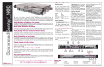
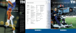
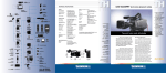
LDK 4482
SuperXpander
User’s Guide
3922 496 48661 St.01
Declaration of Conformity
We, Thomson Broadcast Solutions Nederland B.V., Kapittelweg 10, 4827 HG Breda, The Netherlands declare under
our sole responsibility that this product is in compliance with the following standards:
: Safety
EN60065
EN55103-1 : EMC (Emission)
EN55103-2 : EMC (Immunity)
following the provisions of:
a. the Safety Directives 73/23//EEC and 93/68/EEC
b. the EMC Directives 89/336/EEC and 93/68/EEC
FCC Class A Statement
This product generates, uses, and can radiate radio frequency energy and if not installed and used in accordance with
the instructions, may cause interference to radio communications.
It has been tested and found to comply with the limits for a class A computing device pursuant to Subpart J of part 15
of FCC rules, which are designed to provide reasonable protection against such interference when operated in a commercial environment.
Operation of this product in a residential area is likely to cause interference in which case the user at his own expense
will be required to take whatever measures may be required to correct the interference.
Copyright
Für diese Unterlage behalten wir uns
alle Rechte vor (Gemäß DIN 34).
Technische Änderungen im Zuge der
Weiterentwicklung vorbehalten.
Copying of this document and giving
it to others, and the use or communication of the contents thereof,
are forbidden without express authority. Offenders are liable to the
payment of damages. All rights are
reserved in the event of the grant of
a patent or the registration of a utility
model or design. Liable to technical
alterations in the course of further
development.
© Thomson Multimedia Broadcast Solutions 2002
Toute communication ou reproduction de ce document, toute exploitation ou communication de son
contenu sont interdites, sauf autorisation expresse. Tout manquement à cette règle est illicite et
expose son auteur au versement de
dommages et intérêts. Tous nos
droits sont réservés pour le cas de la
délivrance d'un modèle d'utilité. Sous
réserve de modification au cours de
l'évolution technique.
LDK 4482
SuperXpander
User's Guide
Contents
Location of Controls and Functions ................... 1-2
Location of Controls and Functions for HS ........ 1-4
02.38.3
Connections ..................................................... 1-10
Service Information .......................................... 1-14
User's Guide LDK 4482 - SuperXpander
1-1
Location of Controls and Functions
Rear Panel
1
2
FILTER
0
3
4
MSC.
0
1(CLR)
0
4
6
7
VIEWFINDER
Camera on
Pip
5
0
0
9
10
SIGN
0
R
Remote
8
0
Centre
cross
0
Lamp
off
Ext 1
Heater
0
0
2
0
0
3
1
0
0
Auto
white
5
On air
0
6
0
Optical filter selection
Pressing this switch starts the automatic white balance
process. This switch is in parallel with the AWB
switch at the front/left of the camera and operates in
the same way.
The LED in the switch flashes during the auto-white
process. (The operation of this switch depends on the
user level that has been set for the camera.)
3
0
0
Safe
zone
0
B
4
Automatic white balance switch
0
G
VF
Boost
Select the optical filter by touching the appropriate
numbered switch. Switch 1 : Clear filter
Switch 2 : ND 0.6 filter
Switch 3 : ND 1.2 filter
Switch 4 : ND 1.8 filter
Switch 5 : 4 Point Star filter
Switch 6 : 6 Point Star filter
The LED in the switch flashes during a change and
then lights continuously to indicate the selected filter.
(The operation of this switch depends on the user
level that has been set for the camera.)
2
0
Select
0
Ext 2
0
Focus
ind
Dimm
0
Y/ext
Call
LED indicators
CAMERA ON : lights when the camera is receiving
power.
REMOTE
: lights when the camera is in the
remote control mode.
HEATER
: lights when the lens heater is on.
ON AIR
: the red LED lights when the camera
is on air.
: the yellow LED lights when the ISO
signal is activated.
5
Viewfinder R, G and B switches
Switches the R, G or B signal from the camera for
display in the viewfinder. When an R, G or B switch is
deselected, the Y or Y + c signal is displayed.
The selection of the Y or Y+c (contours added) signal
is carried out in the Vf/Lens \ Vf Inst \ Vf mon menu
on camera.
6
Viewfinder indicators switch
Switches the centre cross, safe area and focus
indicators in the viewfinder on and off.
VTR switch
When pressed it starts or stops the VTR when the
camera is in the local control mode.
1-2
User's Guide LDK 4482 - SuperXpander
02.38.3
1
2
FILTER
0
3
4
MSC.
0
1(CLR)
0
4
6
7
8
VIEWFINDER
Camera on
Pip
5
0
10
SIGN
0
0
0
Centre
cross
R
Remote
9
0
Lamp
off
Ext 1
Heater
0
0
2
0
0
3
7
0
0
Auto
white
5
On air
0
6
0
Viewfinder EXT1, EXT2 and
Y switches
0
0
0
0
Ext 2
0
Focus
ind
B
8
0
Safe
zone
G
VF
Boost
Switches the Ext 1 and Ext 2 signal for display in the
viewfinder. Ext 1 and Ext 2 are also selectable with
the pan-bar switches.
Y/ext on switches a mix of Y and Ext 1 or Ext 2 signal
for display in the viewfinder.
Y/ext off switches only Ext 1 or Ext 2 signal for display
in the viewfinder.
If no switch is selected the previous signal is displayed
(R, G, B, Y or Y+c).
The Y or Y+c (contours added) signal is selected in
the Vf/Lens \ Vf Inst \ Vf mon menu on the camera.
Note: Viewfinder and External selection switches on
the camera are disabled.
02.38.3
0
Select
Dimm
0
Y/ext
Call
Dim
Switches the brightness of the on-air lamp on the
viewfinder up and down in steps.
9
On air lamp switch
If function On air is on you can switch the on air lamp
on the lens and 7-inch viewfinder on and off.
Note:
For function On air see Installation Manual Base
Station.
10 Call switch
Pressing this switch sends a signal to the control
panels calling for attention. An incoming call activates
the LED in the switch.
User's Guide LDK 4482 - SuperXpander
1-3
Location of Controls and Functions for HS
Rear Panel
1
FILTER
0
2
3
MSC.
0
1(CLR)
0
4
5
VIEWFINDER
Camera on
Pip
4
0
SIGN
0
0
R
Remote
0
Centre
cross
0
Lamp
off
Ext 1
Heater
0
0
2
0
0
3
1
0
0
Auto
white
5
0
0
0
Pip switch
4
VF Boost switch
0
Safe
zone
0
B
This switch is used to add an extra 18dB amplification
to the viewfinder contours.
This function can be used as a "focus assist" tool for
the camera man.
3
0
G
6
Switches on the PIP signal on the viewfinder screen.
2
0
On air
0
Ext 2
0
Focus
ind
Dimm
0
Y/ext
Call
Up switch
This up scroll switch is used to directly move through
frequently used menus, displayed in the viewfinder
screen.
5
Select switch
This switch, when pressed, selects the particular
menu that is pointed out by the cursor in the display
or sets an on/off function.
Down switch
This down scroll switch is used to directly move
through frequently used menus, displayed in the
viewfinder screen.
1-4
User's Guide LDK 4482 - SuperXpander
02.38.3
Left Panel
1
2
3
4
5
6
70 VA max
1
Triaxial cable connector
4
Connects the large lens adapter to the base station
and carries all signals and power.
2
This fuse protects the utility outlet. Replace only with
the same type - T1A/115V or T0.5A/230V.
3
Script light connector
A 3-pole socket which supplies +12 Vdc (500 mA) for
a script board light. (Script board LDK 6985/15 does
not connect to this socket but to the socket at the rear
of the camera.)
Utility outlet
Supplies power (maximum 70W) at the mains supply
voltage and frequency. (Loading or unloading this
outlet could interrupt camera operation.)
02.38.3
Lights when power is available at the utility outlet.
5
Utility outlet fuse
Utility outlet power indicator
6
Camera triaxial flying lead
Connects the large lens adapter to the camera.
User's Guide LDK 4482 - SuperXpander
1-5
Right Panel
1
2
3
4
5
7
6
8
POWER
WARNING
VF.2>
>VF.1
>External
THIS APPARATUS
MUST BE EARTHED
OFF
REMOTE
LOCAL
230V AC T1.6A
50-60 Hz
115V AC T4A
1
Second viewer socket (VF2)
A 12-pole male socket for the connection of a second
viewer.
2
CVBS input socket
Mains power supply input (Local
power)
Input voltage for NTSC version: 115 Vac (±15%)
Fuse: 4A Slow, 250 Vac
Input voltage for PAL version: 230 Vac (±15%)
Fuse: 1.6A Slow, 250 Vac
The frequency of the mains power supply must be
between 47Hz and 63Hz.
1-6
Mains power supply On/Off switch
Switches the mains power supply to the large lens
adapter on or off. (It does not switch off the power to
the utility outlet.)
6
Local / Remote power switch
Switches the large lens adapter to the local or remote
power mode.
7
A BNC socket which supplies a video signal for a
monitor or a second viewer connected to the VF2
socket.
4
LENS (cam)
Video 1 input socket
A BNC socket which supplies a video signal for a
monitor or a second viewer connected to the VF2
socket.
3
5
VF (cam)
Viewfinder flying lead
Connects the camera viewfinder signal and data bus
to the large lens adapter (the large lens adapter
passes the signal to the top-mounted viewfinder).
8 Lens flying lead
Connects the lens connector at the front of the large
lens adapter to the camera.
User's Guide LDK 4482 - SuperXpander
02.38.3
Assembly
Viewfinder Mount
Retaining Knob
LDK 10P
Support
rail slot
Lens
Locking
Handle
70 VA max
Lens
support
rail
Balance Knob
Bayonent Ring
Locking Lever
It is important that you assemble and disassemble the
units in the right order. The correct order of assembly
is as follows:
1. Attach the large lens adapter to the tripod.
2. Mount the lens onto the large lens adapter.
3. Attach the camera to the large lens adapter.
4. Mount the 7-inch viewfinder onto the large lens
adapter.
To disassemble the units follow this order in reverse.
Tripod
To mount the large lens adapter on a tripod, first
attach the tripod wedge plate to the underside of the
adapter as follows:
a. Lie the large lens adapter on its side.
b. Ensure that the flat side of the tripod wedge plate
is against the underside of the large lens adapter.
c. Secure the tripod wedge plate to the large lens
adapter by screwing four M6 x 16 screws into the
holes provided.
d. Slide the large lens adapter onto the tripod and lock
in place with the tripod locking bar and security pin.
02.38.3
Mounting a Lens
To mount the lens onto the large lens adapter, proceed
as follows:
a. Slide the viewfinder support back towards the rear
of the large lens adapter.
b. Hook the lens onto the support rail ensuring that
the upper lens pin fits into the slot in the support
rail.
c. Swing the lens downwards so that the lower lens
pin fits into the hole in the front of the camera.
d. Turn the lens locking handle clockwise to secure
the lens in place.
If the lens cannot be secured see Information
on the next page
To remove the lens, remove the camera from
the large lens adapter first, then follow this
procedure in reverse.
User's Guide LDK 4482 - SuperXpander
1-7
NOTE:
Due to tolerances it is possible
that the lens cannot be secured.
Therefore there are two knurled
screws on top of the Electronic
Unit with which the Camera
attachment block can be adjusted.
Turn the screws clockwise to raise
the
block
and
turn
counterclockwise to lower the
block.
2
Adjustment
screws
Camera
attachment
block
Adjustment
screws
Attaching the Camera
When using an LDK10P/00 or 01 before attaching
the camera remove from the handgrip items 19, 6,
7, 14 and 5. See Service Manual LDK10P.
Attach the camera to the large lens adapter only after
the lens is mounted. Proceed as follows:
a. Remove the 1.5 inch viewfinder support bracket at
the front of the camera handle.
b. Mount the bayonet ring locking lever to the front of
the camera and ensure that the bayonet ring is
open.
CAUTION
Do not tighten the screw to much as this could
deform the bayonet-ring.
Check that lever can close ring smoothly.
c. Place the camera onto the footbed but do not slide
it home yet.
d. Connect the lens cable from the large lens adapter
to the lens connector at the side of the camera.
e. Connect the viewfinder cable from the large lens
adapter to the viewfinder connector at the side of
the camera.
f. Push the camera all the way home along the
wedge-shaped groove so that the stud on the
footbed engages the bottom rear of the camera
and the bayonet ring engages the lens.
g. Turn the bayonet ring locking lever on the front of
the camera downwards so that the camera is
connected to the lens.
1-8
h. Plug the flying triax lead from the left side panel of
the large lens adapter into the rear of the camera.
i. Connect the triax cable from the base station to the
connector on the left side of the large lens adapter.
Camera Balance
When the lens and camera are mounted on the large
lens adapter it may be necessary to balance the large
lens adapter on the tripod as follows:
a. Loosen the balance knob on the side of the footbed
by turning it counterclockwise.
b. Move the footbed back and forth along the tripod
until the best balance is achieved.
Caution
Ensure that the ribs mesh correctly
c. Tighten the balance knob on the side of the footbed
by turning it clockwise.
User's Guide LDK 4482 - SuperXpander
02.38.3
Cable Clamp
Rain and Off-use Cover
When the lens and camera are mounted on the large
lens adapter it is necessary to clamp the camera
cable. Proceed as follows:
a. Loosen the cable clamp on the right side of the
footbed by turning it counterclockwise.
b. Put the cable into the clamp.
c. Tighten the cable clamp by turning it clockwise.
The rain and off-use cover LDK6989/00 must be used
when the camera system is in wet or damp environment.
This protection is necessary for personal safety
reasons. The cover can also be used in dusty
environments. It can also be useful if the camera is
being put into storage.
Dimensions
Mounting the Viewfinder
The dimensions of the large lens adapter are:
To mount the viewfinder on top of the large lens
adapter proceed as follows:
a. Slide the viewfinder along the rails on top of the
camera until it can go no further.
b. Push both locking levers inwards and slide the
viewfinder until it firmly engages the connector.
c. Release the locking levers and ensure they click
into the lock position.
d. Loosen the viewfinder mount retaining knob on top
of the large lens adapter.
e. Slide the viewfinder mount along the rails until it is
in the desired position.
f. Tighten the viewfinder retaining knob on top of the
large lens adapter.
Length: 600 mm
Width: 350 mm
Height: 390 mm
The weight of the large lens adapter does not exceed
17 Kg (excluding lens, camera and 7-inch viewfinder
but including wedge plate).
Mounting the Scriptboard
To mount the scriptboard onto the large lens adapter,
proceed as follows:
a. Mount the separately delivered scriptboard quick
mounting pin to the scriptboard clamp of the large
lens adapter. Tighten with screw 6 and secure with
screw 738. The scriptboard clamp can be mounted
on the right as well as on the left side of the large
lens adapter. The scriptboard quick mounting pin
can also be mounted on top of the camera.
b. Click the scriptboard over the quick mounting pin.
Quick mounting pin
Scriptboard clamp
736
02.38.3
User's Guide LDK 4482 - SuperXpander
1-9
Connections
Connector Signals
In each of the following figures the connectors are
shown as seen on the panels of the camera. Remember
to use the mirror image of the drawings to identify the
pins on the solder side of the connector. The part
numbers of the panel connectors can be found in the
spare parts lists of the service manual.
Utility Outlet Connector (X602)
3
1
Eurostyle 3-pin female
2
1. Neutral
2. Line
3. Earth
Voltage:
115/230 Vac
Maximum power: 70 VA
Script Light Connector (X604)
1
3-pin female
1. +12V (500mA)
2. GND (+12V return)
3. Housing
Shield of cable directly to the connector housing.
2
3
1-10
User's Guide LDK 4482 - SuperXpander
02.38.3
Monitor Connector (X608)
12-pin male
1
9
1. Housing
2. -80V
3. no connection
4. +13V
5. no connection
6. D-SCL
7. GND
8. D-SDA
9. D-INTN
10.Video 2 in
11.Video return
12.Video 1 in
10
2
3
8
11
12
4
7
6
5
Shield of cable directly to the connector housing.
Mains Supply Input Connector (X601)
3
Eurostyle 3-pin male
1
2
1. Neutral
2. Line
3. Earth
Viewfinder Flying Lead Connector (X612)
9
12-pin female
1
10
8
7
2
12
11
6
4
5
3
1. Shield
2. no connection
3. no connection
4. no connection
5. no connection
6. D-SCL
7. GND
8. D-SDA
9. D-INTN
10.no connection
11.Video return
12.VF video
Shield of cable directly to the connector housing.
02.38.3
User's Guide LDK 4482 - SuperXpander
1-11
Lens Flying Lead Connector (X611)
12-pin male
1
9
10
2
3
8
11
7
12
4
6
5
1. no connection
2. no connection
3. GND (power ret.)
4. no connection
5. Iris control
6. no connection
7. Iris follow
8. Iris auto/remote
9. no connection
10.Zoom follow
11.Focus follow
12.Spare
Shield of cable directly to the connector housing.
Top Viewfinder Connector (X605)
15-pin female
8
15
1
9
1.
2.
3.
4.
5.
6.
7.
8.
9.
10.
11.
12.
13.
14.
15.
VF video
CVBS/Ext. Video
no connection
GND (+12V return)
Housing
+12V
SDL
no connection
VF video return
CVBS/Ext. Video return
+12v
GND (+12V return)
Housing
On-air lamp
SDA
Shield of cable directly to the connector housing.
1-12
User's Guide LDK 4482 - SuperXpander
02.38.3
Lens Connector (X603)
36-pin female
18
1
36
19
1.
2.
3.
4.
5.
6.
7.
8.
9.
10.
11.
12.
13.
14.
15.
16.
17.
18.
19.
20.
21.
22.
23.
24.
25.
26.
27.
28.
29.
30.
31.
32.
33.
34.
35.
36.
not used
not used
not used
+12V
GND (power return)
GND (servo return)
Housing
R.E. A
R.E. B
R.E. C
not used
Iris F. (follow)
Zoom F. (follow)
Ext SW 1
Ext SW 2
not used
Iris
Iris A/R (auto/remote)
Zoom
Focus
On-airN (tally control)
ZF-L/R (zoom, focus local/remote)
Ext SW 3
Lens ID 0
Lens ID 1
Lens ID 2
Lens ID 3
not used
not used
Focus F. (follow)
not used
not used
Eng SW
Prod SW
not used
not used
Shield of cable directly to the connector housing.
02.38.3
User's Guide LDK 4482 - SuperXpander
1-13
Service Information
When using the Large Lens Adaptor with older
Viewfinders LDK4016/02 it is possible that a hum
appears in the picture. Also no text display will be
available. To solve these problems the following
changes in the Viewfinder LDK4016/02 have to be
performed.
Video Board 3922 406 81721 status 9
Remove C4
ZR27 was 3K3 becomes 12K code number
4822 051 51203
In place of the not mounted ZR20 mount a
capacitor of 22 nF (ZC22) code number 4822
122 31797
Old status 9
New status 10
Power/Deflection Board 3922 406 81731 status 9
Connect pin 5 of ZIC100 to the 0V pin 1 or 8 of
ZIC100
Old status 9
New status 10
1-14
User's Guide LDK 4482 - SuperXpander
02.38.3