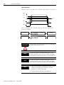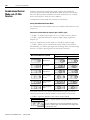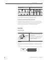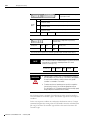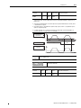
1
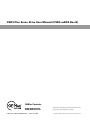
Maximum Value for OEMs
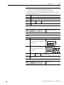
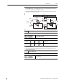
SM
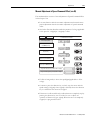
CSD3 Plus Servo Drive
(CSD3-xxBX2 Rev.B)
User Manual
Important User Information
Solid state equipment has operational characteristics differing from those of
electromechanical equipment. Because of this difference, and also because of
the wide variety of uses for solid state equipment, all persons responsible for
applying this equipment must satisfy themselves that each intended application
of this equipment is acceptable.
In no event will Rockwell Automation Korea, Ltd. be responsible or liable for
indirect or consequential damages resulting from the use or application of this
equipment.
The examples and diagrams in this manual are included solely for illustrative
purposes. Because of the many variables and requirements associated with any
particular installation, Rockwell Automation Korea, Ltd. cannot assume
responsibility or liability for actual use based on the examples and diagrams.
No patent liability is assumed by Rockwell Automation Korea, Ltd. with
respect to use of information, circuits, equipment, or software described in this
manual.
Reproduction of the contents of this manual, in whole or in part, without
written permission of Rockwell Automation Korea, Ltd., is prohibited.
Throughout this manual, when necessary, we use notes to make you aware of
safety considerations.
WARNING
IMPORTANT
ATTENTION
WARNING
BURN HAZARD
Identifies information about practices or circumstances that can
cause an explosion in a hazardous environment, which may lead to
personal injury or death, property damage, or economic loss.
Identifies information that is critical for successful application and
understanding of the product.
Identifies information about practices or circumstances that can
lead to personal injury or death, property damage, or economic loss.
Attentions help you identify a hazard, avoid a hazard, and recognize
the consequence
Labels may be located on or inside the equipment, for example, a
drive or motor, to alert people that dangerous voltage may be
present.
Labels may be located on or inside the equipment, for example, a
drive or motor, to alert people that surfaces may be at dangerous
temperatures.
CSD3 and CSD3P are trademarks of Rockwell Automation Korea, Ltd.
Trademarks not belonging to Rockwell Automation Korea, Ltd. are property of their respective companies.
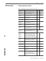
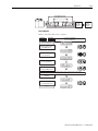
Table of Contents
Summary of Change
Preface
About This Publication . . . . . . . . . . . . . . . . . . . . . . . . . . . . . . . . . . . .
Who Should Use this Manual . . . . . . . . . . . . . . . . . . . . . . . . . . . . . . .
Conventions Used in This Manual . . . . . . . . . . . . . . . . . . . . . . . . . . .
Additional Resources. . . . . . . . . . . . . . . . . . . . . . . . . . . . . . . . . . . . . .
P-1
P-1
P-1
P-2
Chapter 1
Before Using the CSD3 Servo Drive Introduction . . . . . . . . . . . . . . . . . . . . . . . . . . . . . . . . . . . . . . . . . . . . . 1-1
Safety Precautions . . . . . . . . . . . . . . . . . . . . . . . . . . . . . . . . . . . . . . . . 1-2
How to Use This Manual . . . . . . . . . . . . . . . . . . . . . . . . . . . . . . . . . . 1-3
Terminology . . . . . . . . . . . . . . . . . . . . . . . . . . . . . . . . . . . . . . . . . 1-3
Notation Description . . . . . . . . . . . . . . . . . . . . . . . . . . . . . . . . . . 1-3
Manual Description Order . . . . . . . . . . . . . . . . . . . . . . . . . . . . . . 1-5
Others . . . . . . . . . . . . . . . . . . . . . . . . . . . . . . . . . . . . . . . . . . . . . . 1-5
Product Type and Each Part Name . . . . . . . . . . . . . . . . . . . . . . . . . . 1-6
Name of Each Part of the Drive . . . . . . . . . . . . . . . . . . . . . . . . . 1-6
Model Number of the Drive. . . . . . . . . . . . . . . . . . . . . . . . . . . . . 1-7
Drive Type (by capacity) . . . . . . . . . . . . . . . . . . . . . . . . . . . . . . . . 1-7
Name of Each Motor Part . . . . . . . . . . . . . . . . . . . . . . . . . . . . . . 1-8
Model Number of the Motor . . . . . . . . . . . . . . . . . . . . . . . . . . . . 1-9
Reducer . . . . . . . . . . . . . . . . . . . . . . . . . . . . . . . . . . . . . . . . . . . . 1-10
Chapter 2
Installation
Installation . . . . . . . . . . . . . . . . . . . . . . . . . . . . . . . . . . . . . . . . . . . . . . 2-1
Servo Motor. . . . . . . . . . . . . . . . . . . . . . . . . . . . . . . . . . . . . . . . . . 2-2
Servo Drive . . . . . . . . . . . . . . . . . . . . . . . . . . . . . . . . . . . . . . . . . . 2-4
Chapter 3
Wiring
i
Introduction . . . . . . . . . . . . . . . . . . . . . . . . . . . . . . . . . . . . . . . . . . . . . 3-1
Before You Begin . . . . . . . . . . . . . . . . . . . . . . . . . . . . . . . . . . . . . . . . 3-2
Electric Circuit . . . . . . . . . . . . . . . . . . . . . . . . . . . . . . . . . . . . . . . . . . . 3-3
Name and Function . . . . . . . . . . . . . . . . . . . . . . . . . . . . . . . . . . . 3-3
Electric Circuit Diagram . . . . . . . . . . . . . . . . . . . . . . . . . . . . . . . . 3-5
Using the Socket and Lever . . . . . . . . . . . . . . . . . . . . . . . . . . . . . 3-6
I/O Signal (CN1). . . . . . . . . . . . . . . . . . . . . . . . . . . . . . . . . . . . . . . . . 3-8
I/O Connection Diagram. . . . . . . . . . . . . . . . . . . . . . . . . . . . . . . 3-8
(CN1) Pin Arrangement . . . . . . . . . . . . . . . . . . . . . . . 3-9
(CN1) Input Signal . . . . . . . . . . . . . . . . . . . . . . . . . . . . . . . . . . . . . . 3-11
Sequence Input Signal (allocation) . . . . . . . . . . . . . . . . . . . . . . . 3-11
General Input Signal (fixed) . . . . . . . . . . . . . . . . . . . . . . . . . . . . 3-12
(CN1) Output Signal . . . . . . . . . . . . . . . . . . . . . . . . . . . . . . . . . . . . . 3-13
Sequence Output Signal (Allocation) . . . . . . . . . . . . . . . . . . . . . 3-13
General Output Signal (fixed). . . . . . . . . . . . . . . . . . . . . . . . . . . 3-13
(CN1) Input Circuit and Interface . . . . . . . . . . . . . . . . . . . . . . . . . . 3-15
Pulse Command Input Circuit . . . . . . . . . . . . . . . . . . . . . . . . . . 3-15
Analog Voltage Input Circuit . . . . . . . . . . . . . . . . . . . . . . . . . . . 3-16
Publication CSD3P-UM001E-EN-P — February 2008
ii
Sequence Input Circuit . . . . . . . . . . . . . . . . . . . . . . . . . . . . . . . .
Emergency Stop Signal . . . . . . . . . . . . . . . . . . . . . . . . . . . . . . . .
(CN1) Output Circuit and Interface . . . . . . . . . . . . . . . . . . . . . . . . .
Encoder Wiring (CN2). . . . . . . . . . . . . . . . . . . . . . . . . . . . . . . . . . . .
Pin Arrangement of (CN2) . . . . . . . . . . . . . . . . . . . . . . . . . . . . .
(CN2) Terminal Type. . . . . . . . . . . . . . . . . . . . . . . . . . . . . . . . . .
Encoder Signal Process . . . . . . . . . . . . . . . . . . . . . . . . . . . . . . . .
Wiringthe Battery (BATT) . . . . . . . . . . . . . . . . . . . . . . . . . . . . . . . . .
General Articles Wiring . . . . . . . . . . . . . . . . . . . . . . . . . . . . . . . . . . .
Precautions . . . . . . . . . . . . . . . . . . . . . . . . . . . . . . . . . . . . . . . . . .
Capacity of the Drive and Fuse . . . . . . . . . . . . . . . . . . . . . . . . . .
Noise Protection . . . . . . . . . . . . . . . . . . . . . . . . . . . . . . . . . . . . .
Wiring when Using Several Drives . . . . . . . . . . . . . . . . . . . . . . .
Connection to Peripheral Equipment . . . . . . . . . . . . . . . . . . . . .
3-17
3-17
3-19
3-21
3-21
3-22
3-23
3-31
3-32
3-32
3-33
3-34
3-37
3-38
Chapter 4
Operator, Basic Setting and
Startup
Introduction . . . . . . . . . . . . . . . . . . . . . . . . . . . . . . . . . . . . . . . . . . . . . 4-1
Before You Begin . . . . . . . . . . . . . . . . . . . . . . . . . . . . . . . . . . . . . . . . . 4-2
About Servo-ON Signal. . . . . . . . . . . . . . . . . . . . . . . . . . . . . . . . . 4-2
Table for Parameter Setting. . . . . . . . . . . . . . . . . . . . . . . . . . . . . . 4-4
Operator . . . . . . . . . . . . . . . . . . . . . . . . . . . . . . . . . . . . . . . . . . . . . . . . 4-6
Name and Function of Each Part . . . . . . . . . . . . . . . . . . . . . . . . . 4-6
Icons for the Key Buttons . . . . . . . . . . . . . . . . . . . . . . . . . . . . . . . 4-7
Structure of the Entire Mode . . . . . . . . . . . . . . . . . . . . . . . . . . . . 4-7
Status Display Mode . . . . . . . . . . . . . . . . . . . . . . . . . . . . . . . . . . . 4-8
Overview of the Parameter Setting Mode . . . . . . . . . . . . . . . . . . 4-9
Overview of the Monitor Mode . . . . . . . . . . . . . . . . . . . . . . . . . 4-10
Overview of the Operation Mode. . . . . . . . . . . . . . . . . . . . . . . . 4-11
Basic Setting . . . . . . . . . . . . . . . . . . . . . . . . . . . . . . . . . . . . . . . . . . . . 4-13
Overview of the Basic Setting . . . . . . . . . . . . . . . . . . . . . . . . . . . 4-13
Control Mode Setting . . . . . . . . . . . . . . . . . . . . . . . . . . . . . . . . . 4-14
Motor Setting . . . . . . . . . . . . . . . . . . . . . . . . . . . . . . . . . . . . . . . . 4-16
Main Power Selection . . . . . . . . . . . . . . . . . . . . . . . . . . . . . . . . . 4-20
Startup . . . . . . . . . . . . . . . . . . . . . . . . . . . . . . . . . . . . . . . . . . . . . . . . . 4-22
Before Startup . . . . . . . . . . . . . . . . . . . . . . . . . . . . . . . . . . . . . . . 4-22
Startup. . . . . . . . . . . . . . . . . . . . . . . . . . . . . . . . . . . . . . . . . . . . . . 4-22
Check up Items during Startup . . . . . . . . . . . . . . . . . . . . . . . . . . 4-25
Chapter 5
Function for Control Mode
Publication CSD3P-UM001E-EN-P — February 2008
Introduction . . . . . . . . . . . . . . . . . . . . . . . . . . . . . . . . . . . . . . . . . . . . .
Sequence I/O (Input/Output) Signal . . . . . . . . . . . . . . . . . . . . . . . . .
What is Sequence I/O Signal? . . . . . . . . . . . . . . . . . . . . . . . . . . . .
Function of Output Signal. . . . . . . . . . . . . . . . . . . . . . . . . . . . . . .
Input Signal Allocation Method . . . . . . . . . . . . . . . . . . . . . . . . . .
Output Signal Allocation Method . . . . . . . . . . . . . . . . . . . . . . . . .
Notice for Signal Allocation . . . . . . . . . . . . . . . . . . . . . . . . . . . . .
Position Control Mode. . . . . . . . . . . . . . . . . . . . . . . . . . . . . . . . . . . . .
5-1
5-2
5-2
5-5
5-5
5-7
5-8
5-9
iii
Overview . . . . . . . . . . . . . . . . . . . . . . . . . . . . . . . . . . . . . . . . . . . . 5-9
Standard Wiring Example . . . . . . . . . . . . . . . . . . . . . . . . . . . . . . 5-10
Position Command Pulse . . . . . . . . . . . . . . . . . . . . . . . . . . . . . . 5-11
Position Command Pulse Setting . . . . . . . . . . . . . . . . . . . . . . . . 5-13
Electrical Specifications of Position Command Pulse. . . . . . . . 5-14
Electronic Gear . . . . . . . . . . . . . . . . . . . . . . . . . . . . . . . . . . . . . . 5-15
Position Error Clear (/PCLR) . . . . . . . . . . . . . . . . . . . . . . . . . . 5-21
Pulse Command Inhibition</INHIB> Input . . . . . . . . . . . . . 5-21
Expansion of Electronic Gear Setting . . . . . . . . . . . . . . . . . . . . 5-22
The Second Group of Electronic Gear </GEAR> input . . . . 5-23
Position Completion Signal Detection </P-COM>, Approach
Signal Detection </NEAR> Output. . . . . . . . . . . . . . . . . . . 5-23
Output Width of Allowable Position Error. . . . . . . . . . . . . . . . 5-27
Input/Output Signal Timing diagram . . . . . . . . . . . . . . . . . . . . 5-27
Speed Control Mode . . . . . . . . . . . . . . . . . . . . . . . . . . . . . . . . . . . . . 5-28
Overview . . . . . . . . . . . . . . . . . . . . . . . . . . . . . . . . . . . . . . . . . . . 5-28
Standard Wiring Example . . . . . . . . . . . . . . . . . . . . . . . . . . . . . . 5-29
Speed Command Input . . . . . . . . . . . . . . . . . . . . . . . . . . . . . . . . 5-30
Zero Clamp </Z-CLP> Input. . . . . . . . . . . . . . . . . . . . . . . . . . 5-31
Rotation Direction Switch Input /C-DIR . . . . . . . . . . . . . . . . 5-32
Motor Rotation Start/Stop Input /START. . . . . . . . . . . . . . . . 5-33
Speed Coincidence Output Signal </V-COM> . . . . . . . . . . . . 5-34
Rotation Detection </TG-ON> Output . . . . . . . . . . . . . . . . . 5-35
Speed Limit Function and Speed Limit Detection </V-LMT>
Output . . . . . . . . . . . . . . . . . . . . . . . . . . . . . . . . . . . . . . . . . . . 5-36
Torque Control Mode . . . . . . . . . . . . . . . . . . . . . . . . . . . . . . . . . . . . 5-38
Overview . . . . . . . . . . . . . . . . . . . . . . . . . . . . . . . . . . . . . . . . . . . 5-38
Standard Wiring Example . . . . . . . . . . . . . . . . . . . . . . . . . . . . . . 5-39
Torque Command Input. . . . . . . . . . . . . . . . . . . . . . . . . . . . . . . 5-40
Torque Limit and Torque Limit Detection </T-LMT> Output . . .
5-41
Multi-Step Speed Mode . . . . . . . . . . . . . . . . . . . . . . . . . . . . . . . . . . . 5-45
Overview . . . . . . . . . . . . . . . . . . . . . . . . . . . . . . . . . . . . . . . . . . . 5-45
Standard Wiring Example . . . . . . . . . . . . . . . . . . . . . . . . . . . . . . 5-46
Multi-Step Speed Command Setting . . . . . . . . . . . . . . . . . . . . . 5-47
Combinational Control Mode and </C-SEL> Function . . . . . . . . 5-50
Chapter 6
Tuning by Gain Setting
Introduction . . . . . . . . . . . . . . . . . . . . . . . . . . . . . . . . . . . . . . . . . . . . .
Before you Begin . . . . . . . . . . . . . . . . . . . . . . . . . . . . . . . . . . . . . . . . .
Mark Explanation . . . . . . . . . . . . . . . . . . . . . . . . . . . . . . . . . . . . .
Gain Introduction . . . . . . . . . . . . . . . . . . . . . . . . . . . . . . . . . . . . .
Inertia Ratio . . . . . . . . . . . . . . . . . . . . . . . . . . . . . . . . . . . . . . . . . .
Gain Setting Configuration . . . . . . . . . . . . . . . . . . . . . . . . . . . . . . . . .
Automatic Gain Setting . . . . . . . . . . . . . . . . . . . . . . . . . . . . . . . . . . . .
Auto Tuning . . . . . . . . . . . . . . . . . . . . . . . . . . . . . . . . . . . . . . . . .
Off-line Auto Tuning . . . . . . . . . . . . . . . . . . . . . . . . . . . . . . . . . .
6-1
6-2
6-2
6-2
6-3
6-5
6-7
6-7
6-7
Publication CSD3P-UM001E-EN-P — February 2008
iv
On-line Auto Tuning . . . . . . . . . . . . . . . . . . . . . . . . . . . . . . . . . .
Manual Gain Setting . . . . . . . . . . . . . . . . . . . . . . . . . . . . . . . . . . . . . .
Gain Setting Flowchart . . . . . . . . . . . . . . . . . . . . . . . . . . . . . . . .
Basic Gain Setting . . . . . . . . . . . . . . . . . . . . . . . . . . . . . . . . . . . .
Position, Speed, Torque Related Gain Setting . . . . . . . . . . . . . . . . .
Torque Control Related Gain . . . . . . . . . . . . . . . . . . . . . . . . . . .
Speed Control Related Gain . . . . . . . . . . . . . . . . . . . . . . . . . . . .
Position Control Related Gain . . . . . . . . . . . . . . . . . . . . . . . . . .
Tip to get fast response . . . . . . . . . . . . . . . . . . . . . . . . . . . . . . . . . . .
Feed forward function . . . . . . . . . . . . . . . . . . . . . . . . . . . . . . . . .
Speed Bias Function. . . . . . . . . . . . . . . . . . . . . . . . . . . . . . . . . . .
P/PI Mode Setting Function. . . . . . . . . . . . . . . . . . . . . . . . . . . .
Initial Torque Bias . . . . . . . . . . . . . . . . . . . . . . . . . . . . . . . . . . . .
</G-SEL> Function. . . . . . . . . . . . . . . . . . . . . . . . . . . . . . . . . .
6-10
6-11
6-11
6-12
6-14
6-14
6-16
6-18
6-20
6-20
6-21
6-21
6-25
6-27
Chapter 7
Applications
Publication CSD3P-UM001E-EN-P — February 2008
Introduction . . . . . . . . . . . . . . . . . . . . . . . . . . . . . . . . . . . . . . . . . . . . . 7-1
Motor Suspension. . . . . . . . . . . . . . . . . . . . . . . . . . . . . . . . . . . . . . . . . 7-2
Overview . . . . . . . . . . . . . . . . . . . . . . . . . . . . . . . . . . . . . . . . . . . . 7-2
Servo Alarm (Refer to Chapter 8-6) . . . . . . . . . . . . . . . . . . . . . . . 7-2
Over Travel <P-OT>, <N-OT> . . . . . . . . . . . . . . . . . . . . . . . . . 7-2
Dynamic Brake. . . . . . . . . . . . . . . . . . . . . . . . . . . . . . . . . . . . . . . . 7-4
Motor Brake Control . . . . . . . . . . . . . . . . . . . . . . . . . . . . . . . . . . . . . . 7-6
Change of Motor Rotation Direction . . . . . . . . . . . . . . . . . . . . . . . . 7-10
Regeneration Resistor. . . . . . . . . . . . . . . . . . . . . . . . . . . . . . . . . . . . . 7-11
Regeneration Resistor . . . . . . . . . . . . . . . . . . . . . . . . . . . . . . . . . 7-11
External Regenerative Resistor . . . . . . . . . . . . . . . . . . . . . . . . . . 7-12
Regenerative Resistor Selection Standard . . . . . . . . . . . . . . . . . . 7-13
Setting for Smooth Operation . . . . . . . . . . . . . . . . . . . . . . . . . . . . . . 7-16
Speed Limiting Function . . . . . . . . . . . . . . . . . . . . . . . . . . . . . . . . . . 7-18
Position Feedback to the Host Controller . . . . . . . . . . . . . . . . . . . . 7-21
Direction Change of Output Pulse . . . . . . . . . . . . . . . . . . . . . . . 7-21
Pulse Dividing Circuit . . . . . . . . . . . . . . . . . . . . . . . . . . . . . . . . . 7-22
Analog Monitor Output . . . . . . . . . . . . . . . . . . . . . . . . . . . . . . . . . . . 7-25
Use of Absolute Encoder. . . . . . . . . . . . . . . . . . . . . . . . . . . . . . . . . . 7-27
What is an Absolute Encoder? . . . . . . . . . . . . . . . . . . . . . . . . . . 7-27
Contact with the Host Controller . . . . . . . . . . . . . . . . . . . . . . . . 7-28
Battery. . . . . . . . . . . . . . . . . . . . . . . . . . . . . . . . . . . . . . . . . . . . . . 7-28
Reset of Absolute Encoder . . . . . . . . . . . . . . . . . . . . . . . . . . . . . 7-30
Data Transmission of Absolute Encoder . . . . . . . . . . . . . . . . . . 7-32
Operation Mode Function . . . . . . . . . . . . . . . . . . . . . . . . . . . . . . . . . 7-35
Things to Know First. . . . . . . . . . . . . . . . . . . . . . . . . . . . . . . . . . 7-35
Jog Operation (run-00) . . . . . . . . . . . . . . . . . . . . . . . . . . . . . . . . 7-35
Off-line Auto Tuning Operation (run-01) . . . . . . . . . . . . . . . . . 7-36
Searching an Origin Pulse(run-02) . . . . . . . . . . . . . . . . . . . . . . . 7-38
Auto Adjustment of Speed Command Offset (run-03) . . . . . . . 7-38
Auto Adjustment of Torque Command Offset (run-04). . . . . . 7-39
v
Manual Adjustment of Speed Command Offset (run-05). . . . .
Manual Adjustment of Torque Command Offset (run-06) . . .
Adjustment of Current Feedback Offset (run-07). . . . . . . . . . .
Alarm Reset (run-08). . . . . . . . . . . . . . . . . . . . . . . . . . . . . . . . . .
Alarm History Clear (run-09) . . . . . . . . . . . . . . . . . . . . . . . . . . .
Absolute Encoder Reset (run-10). . . . . . . . . . . . . . . . . . . . . . . .
2-Group Gain Storing (run-11) . . . . . . . . . . . . . . . . . . . . . . . . .
Parameter Initialization (run-12). . . . . . . . . . . . . . . . . . . . . . . . .
Monitor Mode Function . . . . . . . . . . . . . . . . . . . . . . . . . . . . . . . . . .
Introduction of Monitor Function . . . . . . . . . . . . . . . . . . . . . . .
Key Button Operation . . . . . . . . . . . . . . . . . . . . . . . . . . . . . . . .
7-41
7-42
7-43
7-44
7-45
7-46
7-47
7-48
7-50
7-50
7-52
Chapter 8
Inspection and Protection
Functions
Introduction . . . . . . . . . . . . . . . . . . . . . . . . . . . . . . . . . . . . . . . . . . . . . 8-1
Inspection. . . . . . . . . . . . . . . . . . . . . . . . . . . . . . . . . . . . . . . . . . . . . . . 8-2
Inspection of Motor . . . . . . . . . . . . . . . . . . . . . . . . . . . . . . . . . . . 8-2
Inspection of Drive . . . . . . . . . . . . . . . . . . . . . . . . . . . . . . . . . . . . 8-2
Part Inspection . . . . . . . . . . . . . . . . . . . . . . . . . . . . . . . . . . . . . . . 8-3
Battery Inspection for absolute Encoder (7.9.3) . . . . . . . . . . . . . 8-3
Protection Function. . . . . . . . . . . . . . . . . . . . . . . . . . . . . . . . . . . . . . . 8-4
Servo Warning . . . . . . . . . . . . . . . . . . . . . . . . . . . . . . . . . . . . . . . . 8-4
Servo Alarm. . . . . . . . . . . . . . . . . . . . . . . . . . . . . . . . . . . . . . . . . . 8-6
Confirmation before Requesting for A/S . . . . . . . . . . . . . . . . . 8-14
Appendix A
Parameter List
Introduction . . . . . . . . . . . . . . . . . . . . . . . . . . . . . . . . . . . . . . . . . . . . . A-1
Parameter List . . . . . . . . . . . . . . . . . . . . . . . . . . . . . . . . . . . . . . . . . . . A-2
Summary of Parameters . . . . . . . . . . . . . . . . . . . . . . . A-2
Parameter Group 0. . . . . . . . . . . . . . . . . . . . . . . . . . A-7
Parameter Group 1 . . . . . . . . . . . . . . . . . . . . . . . . . . . . . . . . . . . A-15
Pr-1.14: Current Controller BW . . . . . . . . . . . . . . . . . . . . . . . . . A-20
Pr-1.15: Velocity Response Level . . . . . . . . . . . . . . . . . . . . . . . . A-21
Parameter Group 2 . . . . . . . . . . . . . . . . . . . . . . . . . . . . . . . . . . . A-21
Parameter Group 3 . . . . . . . . . . . . . . . . . . . . . . . . . . . . . . . . . . . A-25
Parameter Group 4 . . . . . . . . . . . . . . . . . . . . . . . . . . . . . . . . . . . A-29
Parameter Group 5 . . . . . . . . . . . . . . . . . . . . . . . . . . . . . . . . . . . A-32
Operation Mode Function List. . . . . . . . . . . . . . . . . . . . . . . . . . A-40
Monitor Mode Function List . . . . . . . . . . . . . . . . . . . . . . . . . . . A-42
Appendix B
Servo Drive Specification
Introduction . . . . . . . . . . . . . . . . . . . . . . . . . . . . . . . . . . . . . . . . . . . . .
Servo Drive Specification . . . . . . . . . . . . . . . . . . . . . . . . . . . . . . . . . .
Outline Drawing . . . . . . . . . . . . . . . . . . . . . . . . . . . . . . . . . . . . . .
Specification. . . . . . . . . . . . . . . . . . . . . . . . . . . . . . . . . . . . . . . . . .
B-1
B-2
B-2
B-4
Publication CSD3P-UM001E-EN-P — February 2008
vi
Publication CSD3P-UM001E-EN-P — February 2008
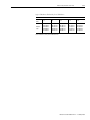
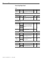
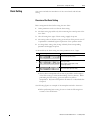
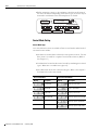
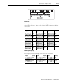
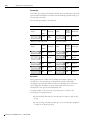
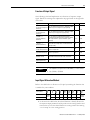
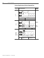
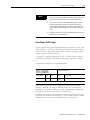
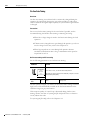
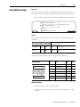
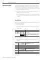
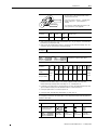
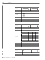
Summary of Change
You will see change bars to the left or right of a paragraph throughout this
manual to help you quickly indentify revisions.
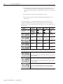
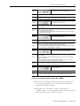
Manual Revision
Changes
Date
A
N/A
N/A
B
Initial draft
October 2006
C
Correction of typos such as model name or
connect name
May 2007
D
Firmware Update V2.4 -> V2.5(1)
November 2007
E
Changes added to CSD3-xxBX2 Rev.B Servo Drive February 2008
1. New Parameter
• Pr-1.15 (Velocity Response Level) A-21(2)
2. Changed Prameter Values
• Pr-0.03 (Autotuning mode) A-2(2)
• Pr-0.14 (Protocol, Data Format, Baudrate)
A-13(2)(3)
• Pr-1.00 (System Gain) A-15(2)
• Pr-1.07 (Vibration Suppression Filter)
A-18(2)
3. Max. Frequency of Pulse Command (Open
Collector) is changed to 200kpps (300kpps
before). 3-15
4. Contact Input is changed to bi-directional
(unidirectional before). 3-8
(1)
For more information on firmware update, refer to CSD3 Plus Firmware Update Release Note, Ver2.50 (Publication No. CSD3-RN002A).
(2)
For more information on each changed parameter, refer to the corresponding page.
(3)
For more information on ASCII & Modbus-RTU Protocol, refer to ‘CSD3 Servo Drive ASCII & Modbus-RTU Protocol Reference Manual (Publication CSD3-RM001).’
1
Publication CSD3P-UM001E-EN-P — February 2008
SOC-2
Summary of Change
Publication CSD3P-UM001E-EN-P — February 2008
Preface
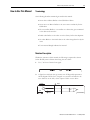
Read this preface to familiarize yourself with the rest of the manual.
About This Publication
This manual provides detailed installation instructions for mounting, wiring,
and troubleshooting your CSD3 Plus servo drive drive, and system integration
for your drive/motor combination with a Motion Card.
Who Should Use this
Manual
This manual is intended for engineers or technicians directly involved in the
installation and wiring of the CSD3 Plus servo drive drive, and programmers
directly involved in the operation, field maintenance, and integration of the
CSD3 Plus servo drive drive with a Motion Card.
If you do not have a basic understanding of the CSD3 Plus servo drive drive,
contact your local OE Max sales representative before using this product, for
information on available training courses.
Conventions Used in This
Manual
The conventions starting below are used throughout this manual.
• Bulleted lists such as this one provide information, not procedural steps
• Numbered lists provide sequential steps or hierarchical information
1
Publication CSD3P-UM001E-EN-P — February 2008
2
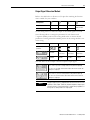
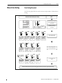
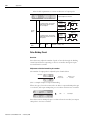
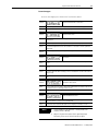
Additional Resources
The following documents contain additional information concerning related
CSD3 Plus servo drive products.
For
Read This Document
Publication Number
Information on the installation of your CSD3 Plus servo drive
CSD3 Plus Servo Drive Installation Instructions
CSD3-IN001
Information on the motors used together with CSD3 Plus servo
drive
Servo Motor User Manual
SMOTOR-UM002
You can view or download publications at
http://www.oemax.co.kr or http://www.oemax.com To order paper copies of
technical documentation, contact your local Rockwell Automation Korea
distributor or sales representative.
Publication CSD3P-UM001E-EN-P — February 2008
Chapter
1
Before Using the CSD3 Servo Drive
Introduction
1
This chapter describes the general matters and optional specifications that you
should know before using the OEMax CSD3 SERVO DRIVE.
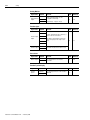
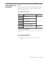
Topic
Page
Introduction
1-1
Safety Precautions
1-2
How to Use This Manual
1-3
Product Type and Each Part Name
1-6
Publication CSD3P-UM001E-EN-P — February 2008
1-2
Before Using the CSD3 Servo Drive
Safety Precautions
This user’s manual describes safety matters using the following marks.
Safety marks deals with the important matters. If the following marks and
contents of each mark are indicated in the contents of this user's manual, you
must be fully aware of them and follow them.
1. The following is a warning mark. This indicates general precautions.
WARNING
When handled incorrectly, dangerous situations or physical damages
may happen.
2. The following is a caution mark. This indicates an important precaution
against an electric shock.
WARNING
When handled incorrectly, dangerous situation (electrocution) may
happen and cause death or severe injury.
3. The following is a caution mark. This indicates precautions against a burn.
WARNING
When handled incorrectly, dangerous situation (burn) may happen and
cause death or severe injury.
4. General Precaution
• This user’s manual may contain some drawings with the cover or
protective shields removed for more detailed and clear explanation.
Make sure to reassemble the device before operation.
• Any modification of the product made by the user is not covered by the
guarantee of quality.
• Rockwell Samsung Automation is not responsible for all injuries or
physical damage caused by any modification of the product made by the
user.
• Contact your Rockwell Samsung Automation agent to order a copy of
this manual if it has been damaged or lost.
Publication CSD3P-UM001E-EN-P — February 2008
Before Using the CSD3 Servo Drive
How to Use This Manual
1-3
Terminology
The following describes terminologies used in this manual.
• Servo drive or Drive: Refers to the CSD3 Servo Drive.
• Servo motor or Motor: Refers to the servo motor exclusively for the
CSD3 drive.
• Host controller: Refers to a controller or a device that gives command
to the drive and controls it.
• Initial value: Refers to the value set at the factory before the shipment.
• Set value: Refers to the initial value or the value changed and set by the
users.
• User’s manual: Simply indicated as ‘manual’.
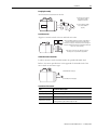
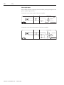
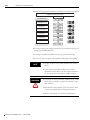
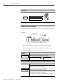
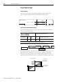
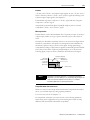
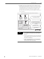
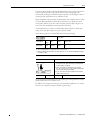
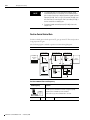
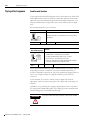
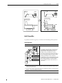
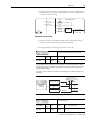
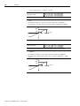
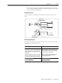
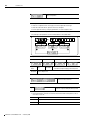
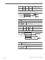
Notation Description
Within the sentences of this manual, the following is expressed as shown
below. Be fully aware of them when using the servo drive.
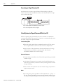
1. Use ‘/’ in front of Active Low signal.
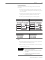
2. A figure box with both the top corners cut off diagonally represents a
circuit diagram. If CN1 for I/O signal or a connector attached to the
servo driver is on the left, it is the output of CN1 or servo drive.
Output
Example
R1
CN1
0[V]
Host controller
Publication CSD3P-UM001E-EN-P — February 2008
1-4
Before Using the CSD3 Servo Drive
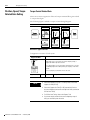
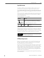
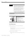
3. If CN1 for I/O signal or a connector attached to servo driver is on the
right, it is the input from the host controller to CN1 or servo drive.
Example
Input
Speed Command
-10[V] ~ +10[V]
P
V-REF
19
V-REF SG
20
CN1
Host controller
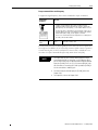
4. The following shows the symbols used on the circuit diagram.
Symbol
Description
Side A Side B
Contact Point
• The figure represents the pin number of the connector, which can be
marked with alphabets rather than the numbers.
• The contact point is the connection between the side A and side B with
the connector.
5. The following figure shows a symbol used to show a twist pair wires to
prevent the noise generation.
Symbol
Figure
Description
Twist the wires where this symbol is located for the noise
prevention.
P
6. The following figure shows a symbol used to show a shield pair wire to
prevent the noise generation.
Symbol
Figure
FG
Publication CSD3P-UM001E-EN-P — February 2008
Shield
Description
Shield the wires where this symbol is located for the noise
prevention.
Before Using the CSD3 Servo Drive
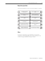
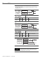
1-5
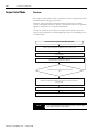
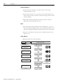
Manual Description Order
This manual is described in the view of users from the purchase to operation.
1
Describes things to know before
using the product.
Describes the outline of product and
marking.
2
3
Describes precautions upon product
installation.
Describes wiring with the host
controller and peripheral equipment.
4
5
Describes the operator for various
settings.
Describes brief functions of the
product.
6
7
Describes the basic settings that
users should set.
Describes the function of the product
for each control modes.
8
9
Describes the tuning to implement
optimum performance of load system.
Describes simple supplementary
functions.
10
11
Describes the protective function,
fault diagnosis and troubleshooting.
Descr i bes i tems cor r espondi ng to
v ar i ous numer i cal data i n the Appendi x .
12
Others
Each chapter or paragraph has a page called Before you begin before
description. For easier understanding of this manual, be fully aware of the
contents of this page called Before you begin in advance.
Publication CSD3P-UM001E-EN-P — February 2008
1-6
Before Using the CSD3 Servo Drive
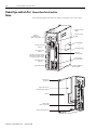
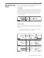
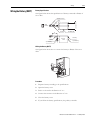
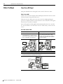
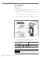
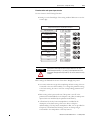
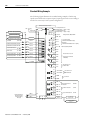
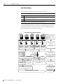
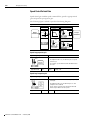
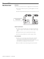
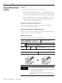
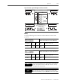
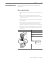
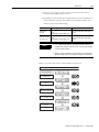
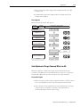
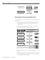
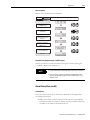
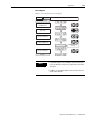
Product Type and Each Part Name of Each Part of the Drive
Name
The following figure introduces the name of each part of the servo drive.
Optional Connector
<CN4>
Battery Connector
<CN5>
Operator
See Chapter 4 for
details of the operator.
Drive Nameplate
AC main Power Input
Terminal
Rated Output Label
Control power input
Terminal
1. DC Main Power Input terminal.
2. DC Reactor Connection Terminal
for suppressing high frequency
Regenerative Resistor
Terminal
Motor Cable Terminal
Mounting Hole
(Top, Bottom)
Regenerative Resistor
(400 [W]or Higher Attached)
Heat Sink
Wiring Socket
(6P, 4P and 3P) 3 Part
Ground Terminal (heat sink)
Publication CSD3P-UM001E-EN-P — February 2008
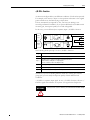
I/O Signals
Connector <CN1>
Encoder Cable
Connector <CN2>
Communication and Operator
Connector <CN3>
Before Using the CSD3 Servo Drive
1-7
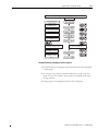
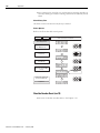
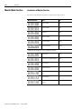
Model Number of the Drive
The following figure describes the model name on the nameplate of the servo
drive.
• The nameplate is attached on the side of the drive case.
• Check the model name on the nameplate, and check if it corresponds to
the product ordered.
• The drive type is Rockwell Samsung Automation Servo Drive CSD3
Series.
• The serial number is included on the nameplate. Be careful not to erase
the serial number during the use.
Nameplate is attached to the drive. Check the model on the nameplate.
Drive Type
C
S
D
Example of Drive Specification
3
0
1
B
X
2
Design Sequence
Mark Rated Output
A5
50 [W]
01
100 [W]
02
200 [W]
04
400 [W]
10
1 [kW]
15
1.5 [kW]
Mark
Voltage
B
AC220 [V]
Drive Type (by capacity)
The table below shows the capacity of drive (rated output) and the capacity of
the applied motor.
Drive Model Name
Drive Capacity
Capacity of the Applied Motor
1
CSD3-A3BX1 (P)
30 [W]
30 [W]
2
CSD3-A5BX1 (P)
50 [W]
50 [W]
3
CSD3-01BX1 (P)
100 [W]
100 [W]
4
CSD3-02BX1 (P)
200 [W]
200 [W]
Publication CSD3P-UM001E-EN-P — February 2008
1-8
Before Using the CSD3 Servo Drive
5
CSD3-04BX1 (P)
400 [W]
300 [W] to 400 [W]
6
CSD3-10BX1 (P)
1 [kW]
500 [W] to 1 [kW]
7
CSD3-15BX1 (P)
1.5 [kW]
1.2 [kW] to 1.5 [kW]
Name of Each Motor Part
The following figure shows the name of each motor part.
• A motor without a brake does not have a brake cable.
• The name of each motor part may differ from the following figure according to
the motor type.
Break Cable
Motor Power Cable
Encoder Cable
Encoder
Nameplate of the
Motor
Motor Frame
Motor Shaft
Mounting Hole
Publication CSD3P-UM001E-EN-P — February 2008
Before Using the CSD3 Servo Drive
1-9
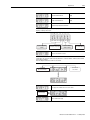
Model Number of the Motor
The following figure describes the model name of the motor on the
nameplate.
The nameplate is attached to the motor. Check the model on the nameplate.
Motor Type
Example of Motor Specification
R S M Z -
0 1 B A 1 A N M 3
Rated Output
Voltage
Encoder Type
Design Sequence
Motor Axis Key Status
Option
Manufacturer
Shaft Specification
This is the description of the model on the nameplate of the motor.
Motor Type
CSM
CSMT
CSMR
CSMQ
CSMZ
CSMD
CSMH
CSMK
RSMD
RSMF
RSMS
RSMH
RSMK
RSML
RSMQ
RSMZ
CSMS
Rated Output
A3
A5
01
02
04
~
~
10
~
50
30 [W]
50 [W]
100 [W] 200 [W] 400 [W] ~
~
1 [kW]
~
5 [kW]
Voltage
A
B
C
D
AC 110 [V]
AC 220 [V]
DC 24 [V]
AC 110/220 [V]
Encoder Type
Motor Model: CSMT/R, RSMS/D/H/F/K/L/Q/Z
Mark
Resolution/1 Encoder Type
Rotation
Mark
Resolution/1 Encoder Type
Rotation
Q
131072
R
131072
Serial Absolute Type
Serial Incremental Type
Publication CSD3P-UM001E-EN-P — February 2008
1-10
Before Using the CSD3 Servo Drive
Motor Type: CSM, CSMT/R
CSMQ/Z/S/D/H/K
RSMS/D/H/F/K/L/Q/Z *1)
Motor Type
Mark
Pulse/1
Rotation
Encoder Type
S
2048
15wire Inc.
Mark
Pulse/1 Rotation
Encoder Type
2500
11wire Inc.
B
2048
9wire Inc.
A*1)
A
2048
Absolute Type
H
2048
Compact
Absolute Type
D
2500
15wire Inc.
M*1)
10000
15wire Inc.
C
2000
15wire Inc.
K
5000
15wire Inc.
K
5000
15wire Inc.
L
6000
15wire Inc.
Motor Axis Key Status
Option
A
B
N
B
S
T
Key
No Key
No Option
With Brake
With Oil Seal
With Brake &
Oil seal
Motor axis specifications
1
2
3
4
Circular
(Coupling
Tightening)
2 Side Slice
(Set screw
tightening)
Key Tightening Tapper
Tightening
5
6
General
Reducer
Harmonic
Drive
Attachment
Reducer
The following figure describes the model name of the reducer on the
nameplate.
Nameplate is attached to the reducer. Check the model on the nameplate.
Reducer Type
Example of Reducer Specification
V R S F - 2 5 C - 2 0 0 - S P T
Mark Reduction Ratio
1/3
Mark
Backlash Grade
Mark
Applicable Motor
Capacity
Mark
Applicable Motor
Model
05
1/5
B
0.7°
030
30 [W]
SPT
CSM Motor
09
1/9
C
050
30 [W]
15
1/15
D
25
1/25
E
0.5°
~
03
800
800 [W]
The backlash grade of the reducer is set at the factory.
Publication CSD3P-UM001E-EN-P — February 2008
Before Using the CSD3 Servo Drive
1-11
Type of Reducers Exclusively for CSM Motor
VRSFReduction
Ratio
1/3
1/5
1/9
1/15
1/25
Reducer
Type
03B-50-SPT
03B-100-SPT
03B-200-SPT
03B-400-SPT
03C-600-SPT
03C-800-SPT
05B-50-SPT
05B-100-SPT
05B-200-SPT
05C-400-SPT
05C-600-SPT
05C-800-SPT
9B-50-SPT
9B-100-SPT
9C-200-SPT
9C-400-SPT
9B-600-SPT
9B-800-SPT
15B-50-SPT
15B-100-SPT
15C-200-SPT
15C-400-SPT
15D-600-SPT
15D-800-SPT
25B-50-SPT
25C-100-SPT
25C-200-SPT
25D-400-SPT
25E-600-SPT
25E-800-SPT
The reducer is only for CSM motors
Publication CSD3P-UM001E-EN-P — February 2008
1-12
Before Using the CSD3 Servo Drive
Publication CSD3P-UM001E-EN-P — February 2008
Chapter
2
Installation
Installation
1
This chapter describes matters to consider when installing the servo drive and
the motor. Refer to the appendix for numerical data on the drive, motor, and
various peripheral equipment necessary for the installation.
Topic
Page
Installation
2-1
Publication CSD3P-UM001E-EN-P — February 2008
2-2
Installation
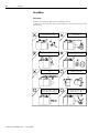
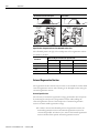
Servo Motor
Precautions
Refer to the following figures when installing a motor.
A motor is a precision part. Pay an extra attention to the encoder, motor shaft,
and bearing.
Publication CSD3P-UM001E-EN-P — February 2008
A shock is the major cause of degrading
the performance of the motor.
Do not connect the motor to the
power directly.
Protect the motor from water or oil.
Pay attention to the concentricity of
coupling connected to the load.
Do not apply continuous stress on the
wire.
The servo motor can be mounted
vertically or horizontally
The oil is applied to the shaft to
prevent it from rusting. Remove it
before installing the servo motor.
The ground wire of the servo motor
must be connected to the grounding
terminal of the servo drive.
Installation
2-3
Coupling Assembly
Avoid excessive instantaneous shocks.
An excessive shock during
the coupling assembly
damages the encoder.
Use the coupling assembly
tools and assemble it
properly.
Encoder
Load Connection
Align the connection shaft of motor and load each other.
After assembling coupling, measure the concentricity of
the motor shaft and the load shaft. By rotating it at
intervals of 90 degrees, measure 4 positions and adjust it
so that the difference between the maximum and minimum
value is less than 0.03 [mm].
If the centers of the axes are different, it leads to
the major cause of performance degradation.
Allowable Load on the Shaft
Loads in the motor shaft should be within the specified allowable load.
Refer to the motor specifications in the appendix for allowable load of the
motor shaft on each motor type.
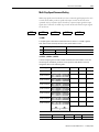
(Vertical)Radial Load [kg.f]
(Horizontal) Thrust Load [kg.f]
Installation Environment
Item
Installation Environment
Storing Temperature
Store it within -20 ~ 60[].
Operating Temperature
Use it within 0 ~ 55[]
Operating Humidity
Use it below 90[%] RH at a place without condensation.
Operating Environment
Use it indoors with well ventilation, at a place for easy checkup and
cleaning, and at a place without explosive gas.
Publication CSD3P-UM001E-EN-P — February 2008
2-4
Installation
Servo Drive
Precautions
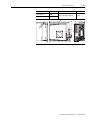
Refer to the following figures when installing the servo drive.
• The most important thing to consider when installing the drive is the ambient
temperature.
• Follow the operational temperature and mount the servo drive vertically.
Servo drive less than 400W applies the natural
convective cooling, and the servo drive with more
than 1kW uses the cooling fan. To increase the
cooling efficiency, install it vertically
<Fixing Bolt>
400 [W] or less : M4xL10
2 mounting holes at the top
& bottom
1 [kW] or more : M5xL10
2~4 mounting holes
depending on the capacity.
When installing several drives, you must the following criteria.
Install a cooling fan to prevent excessive temperature increase.
If the surrounding temperature is higher than the operational temperature, it reduces the performance.
More than
50 [mm]
Pane
More than
50 [mm]
More than 30 [mm]
Publication CSD3P-UM001E-EN-P — February 2008
More than 10 [mm]
Installation
Use the drive in a clean
enviroment where there is no
dust or humidity.
2-5
There is a grounding terminal at the bottom of
the heat sink.
200 [W] or less: 1 mounting hole for M4 bolt
400 [W] or above: 2 mounting holes for M4 bolt
If not grounded, it reduces the performance.
1. Installation Environment
Item
Installation Environment
Storing
Temperature
Store it within -20 to 80 [°C].
Operational
Temperature
Use it within 0 to 55 [°C].
Operational
Humidity
Use it below 90 [%] RH at a place without condensation.
Vibration
Use it below 0.5 [g] (4.9 [m/s2]).
Install a separate cooling device at a place with high ambient temperature and
use it within the operational temperature.
Operational
Location
Recommendations: To maintain reliability for a long time, use it within 0 to 45
[°C].
Use it indoors with well ventilation, at a place for easy checkup and cleaning,
and at a place without explosive gas.
Publication CSD3P-UM001E-EN-P — February 2008
2-6
Installation
Publication CSD3P-UM001E-EN-P — February 2008
Chapter
3
Wiring
Introduction
1
This chapter describes the information on motor, host controller and other
wiring connected to the servo drive, along with the circuit diagram.
Topic
Page
Introduction
3-1
Electric Circuit
3-3
I/O Signal (CN1)
3-8
(CN1) Input Signal
3-11
(CN1) Output Signal
3-13
(CN1) Input Circuit and Interface
3-15
(CN1) Output Circuit and Interface
3-19
Encoder Wiring (CN2)
3-21
Wiringthe Battery (BATT)
3-31
General Articles Wiring
3-32
Publication CSD3P-UM001E-EN-P — February 2008
3-2
Wiring
Before You Begin
Pay attention to the following precautions when wiring.
WARNING
• Wiring should be done only by the qualified personnel.
• High voltage remains in the drive even though the power is off.
Therefore, do not inspect components unless inside “Charge”
lamp is off.
• Pay attention to the polarity when wiring.
WARNING
• The heat sink of the drive generates high heat.
• Pay attention to the heat sink when wiring.
In this chapter, the circuit is divided into electric circuit and signal circuit for
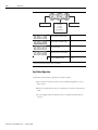
easier and convenient explanation.
Be fully aware of the names of each terminal when reading this user’s manual.
Signal Circuit
Optional Connector
<CN4>
Electric Circuit
Battery Connector
<CN5>
AC Power Terminal
Control Power Terminal
1.DC Power Terminal
2. DC Reactor Connection Terminal for
Suppressing High Frequency
Regenerative Resistor Terminal
Motor Cable Terminal
NOTE
Connector for I/O
Signals <CN1>
Encoder Cable Connector
<CN2>
Communication and
Operator Connector
<CN3>
• The I/O signal connector CN1, encoder cable connector CN2, and
battery connector CN5 are included only in the description of the
signal circuit.
• The description of other connectors are omitted.
Publication CSD3P-UM001E-EN-P — February 2008
Wiring
Electric Circuit
3-3
Name and Function
The terminal symbol is printed on the wiring socket at the electric circuit
terminal of the drive. Observe the drive to identify and understand the
terminals on the following table, and then wire accordingly.
Terminal
L1, L2, L3
AC Power Terminal
400 [W] or lower
Single phase 200 to 230 [V] (50/60 [Hz])
L3 port must not be used.
400 [W] or higher
3 phase 200 to 230 [V] (50/60 [Hz])
Terminal
L1C, L2C
No output division
Single phase 200 to 230 [V] (50/60 [Hz])
Control Power Terminal
• The main power and control power can be divided when connecting to the drive. Therefore, the
user can configure surrounding circuits when the main power is cut off in an emergency or when
the drive itself checks the status and cuts off the power.
• If the drive independently checks the status and only the main power is cut off, but not the control
power, the drive can display the cause of cut-off of the main power. The user can take appropriate
action after identifying the cause of cut-off of the main power.
• Refer to the Chapter 3 for the Electric Circuit Diagram of the power separation.
Terminal
U, V, W
Motor Cable Terminal
Connect the motor cable.
NOTE
• The motor cable connectors (U, V, W) are output terminals. Do not
connect the input power.
• It causes the fire.
Terminal
Grounding Terminal (Heat Sink)
Connect the power and motor cable to the grounding terminal.
Terminal
B1, B2
Regenerative Resistor Connection Port
200 [W] or lower
As the function for regenerative energy consumption is not required, the
regenerative resistor does not have to be mounted.
400 [W] or higher
If the capacity of mounted regenerative resistor is insufficient, remove it
or connect it to the mounted regenerative resistor in parallel.
Refer to the Chapter 7-11 for more information the Regeneration Resistor.
Publication CSD3P-UM001E-EN-P — February 2008
3-4
Wiring
Terminal
DC Main Power Terminal or
DC Reactor Connection Terminal for Suppressing
High Frequency.
DC-, P1, P2
The main power can be input by selecting either terminals (L1, L2 and L3) for the AC main power
terminal, or the terminals (DC- and P1) for the DC main power terminal.
Refer to the Chapter 4-8 for the selection method.
The initial setting is the AC main power input through the terminals (L1, L2 and L3).
When using the AC main power through terminals (L1, L2, L3), the terminals (P1, P2) can be used to
connect the DC reactor for RF control.
P1 and P2 are short-circuited when delivered.
DCP1
P2
External Equipment
Drive
DC Reactor Connection Terminal for Suppressing High Frequency.
P1
DC Reactor
External Equipment
WARNING
P2
Drive
• The main power can be input by selecting either terminals (L1, L2
and L3) for the AC main power terminal, or the terminals (DC- and
P1) for the DC main power terminal.
Connect only either AC main power terminal or the DC main power
terminal.
• When wiring the wiring socket, be careful not to expose the core
wire. It may case an electric shock.
NOTE
• When using the DC main power terminal for the main power
supply, refer to the Chapter 4-8 for information on the setting of
main power input selection.
• If the terminals DC-, P1 and P2 are not used for ‘DC main power
input’ or ‘DC reactor for RF control’, do not remove the short circuit
wire of the terminals (P1 and P2) which is short circuit when
delivered.
Publication CSD3P-UM001E-EN-P — February 2008
Wiring
3-5
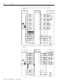
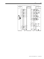
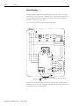
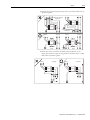
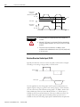
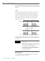
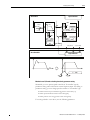
Electric Circuit Diagram
This is a circuit diagram where the main power is supplied from AC
main power input terminal.
Use single-phase power in servo drive whose rated output (capacity) is
400 [W] or lower. Thus, do not use the terminal L3.
POWER
MCCB (Molded Case Circuit Breaker)
MC (Magnetic Contactor)
1MCCB
NOISE
FILTER
1MC
1MC
For more than one second, press
<1> the Push Button S/W which allows
SW1 OFF
SW2 ON
Relay 1
<1>
<2>
Relay 1
the current to flow when pressed.
SUP
Connect this if the power needs to
<3>
<2> be cut-off.
Alarm Display Lamp
Attach a surge suppressor to
<3> the MC relay coil.
CSD3 SERVO DRIVE
All-In-One
MODE
SET
ENTER
1MC
L1
CHARGE
POWER
U
L2
L3
Servo Motor
V
Do not connect this to the drive
with less than 400 [W].
W
L1C
L2C
CN2
N
Regenerative
Resistor
B1
B2
Heat Sink
PG
M
Connect this to the grounding
terminal of th heat snk.
P1
P2
<Shield>
CN1
45
1/2
46
10
SALM+
Relay 1
+24[V]IN
24[V]
SALME-STOP
SW3
Publication CSD3P-UM001E-EN-P — February 2008
3-6
Wiring
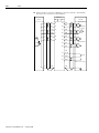
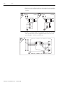
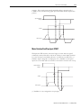
Using the Socket and Lever
This section describes the usage of wiring socket and lever provided
with servo drive.
• Connect only one wire at wire inlet of the socket.
• If the wire is pulled accidentally with an excessive force, rewire it
properly.
• The peeled wire can be used. (Keep the length of the peeled core wire less than
8 [mm].)
• The use of phenol terminal is recommended for the reliability of wiring.
• Use a lever for wires provided with the product.
The following figure shows the sequence of assembling wire at the socket.
• As shown in the figure, insert lever in the socket and press it.
• Insert wire into socket and release the lever.
• Pull it slightly to check if the connection between the socket and wire is normal.
1. Prepare the
wires
4. Strip off the
wires
3. PhenolTerminal
Compression
4. Assemble the
Socket
wire
Terminal
R
<Compress with the Phenol
Terminal Compressor>
Socket
Lever
(Keep the lenght of the peelde wire less than 8 [mm].)
The thickness of wire allowed by the socket is shown below.
Thickness of Wire
Single
Publication CSD3P-UM001E-EN-P — February 2008
∅0.5 to ∅0.8 [mm]
Thickness of Wire
Twist
AWG28 to AWG12
Wiring
WARNING
NOTE
Insert the wire completely.
3-7
If peeled core wire is exposed,
it may cause an electric shock.
The lever is a small tool, used when wiring. Keep it for other
wiring jobs.
Publication CSD3P-UM001E-EN-P — February 2008
3-8
Wiring
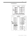
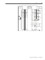
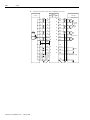
I/O Signal (CN1)
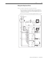
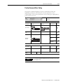
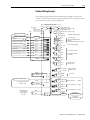
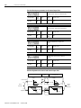
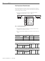
I/O Connection Diagram
This is the circuit diagram of a connector for I/O signal. It is divided into
input on the left and output on the right.
The Backup battery for absolute value encoder can be connected to (CN5) and
(CN1 49, 25). It must be connected to one side only.
DC + 24 [ V]
I/O 50 Pin Connector<CN1>
or
0 [ V]
Input
0 [ V]
Output
28
1
or
DC + 24 [ V]
D/ A
2
23
Sequence
Input Circuit
27
37
Initial Set Function
DI # 1
3
38
P- OT
DI # 2
4
39
N - OT
DI # 3
5
40
/ P- CON
DI # 4
6
/ SV - ON
/ A- RST
DI # 5
7
/ N - TL
DI # 6
8
/ P- TL
DI # 7
9
29
P
30
31
P
32
33
Emergency Stop
E- STOP
P
10
35
.
P
Position
Command
P
34
PULS +
11
PULS -
12
SIGN +
13
SIGN -
P
P
36
AM - SG
AL 1
AL 2
AL 3
AL - SG
Servo Alarm Code
Maximum Allowable Voltage : DC 30 [V]
Maximum Allowable Current : 20[mA]
Alarm Code Output
GND
EA +
EA EB +
Encoder A,B,C Phase
EB -
(Line Receiver SN75175
or MC3486)
EC +
EC PS +
PS -
Rotation Data of the
Absolute Value Encoder
17
/ Z - PULSE +
18
/ Z - PULSE -
14
45
P
Analog Monitor CH1
Output Range : -10 [V] to +10 [V]
Analog Monitor CH2
Output Range : -10 [V] to +10 [V]
AM-SG Analog Monitor Display GND
46
SALM +
Encoder Z-Pulse
OPEN Collector
Servo Alarm
SALM Sequence Output Circuit
41
Speed Command
-10[V]
to ~+10[V]
- 10 [ V]
+ 10 [ V]
Torque Command
-10[V]
to ~+10[V]
- 10 [ V]
+ 10 [ V]
Back-up battery
Back for
- Up
Battery
3.6[V]
absolute
3 . 6 [ V]
encoder
P
P
P
V- REF
19
V- REF SG
20
T- REF
21
T- REF SG
22
BAT +
49
BAT -
25
Publication CSD3P-UM001E-EN-P — February 2008
P
42
43
A/ D
P
44
47
P
24
26
50
X
X
X
48
DO # 1
/ P- COM
DO # 1 DO # 2 +
/ TG - ON
DO # 2 DO # 3 +
BK
DO # 3 -
Initial Set
Function
Wiring
3-9
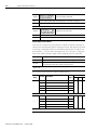
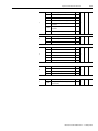
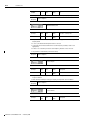
(CN1) Pin Arrangement
Specifications
Pin #
Symbol
1
2
+24 [V] IN
Wire Color
Red
Yellow
Electrical Features
External 24 [V] input for contact point input.
3
DI#1
Blue
4
DI#2
White
5
DI#3
Pink
6
DI#4
Orange
Pin for sequence input signal.
(Terminal input)
7
DI#5
Gray
Refer to the Chapter 5 for details.
8
DI#6
Red 1 Point
9
DI#7
Yellow 1 Point
10
E-STOP
Blue 1 point
11
PULS+
White 1 point
12
PULS-
Pink 1 point
13
SIGN+
Orange 1 Point
14
SIGN-
Gray 1 Point
15
PCLR+
Red 2 Points
16
PCLR-
Yellow 2 Points
17
Z-PULSE+
Blue 2 Points
18
Z-PULSE-
White 2 Points
19
V-REF
Pink 2 Points
20
V-REF SG
Orange 2 Points
21
T-REF
Gray 2 Points
22
T-REF SG
Red 3 Points
Signal input for torque control mode.
Analog torque command -10 [V] to +10 [V].
23
AM-CH2
Yellow 3 Points
Analog monitor CH2. -10 [V] to +10 [V].
24
-
-
-
25
BAT-
White 3 Points
Absolute encoder battery GND.
26
-
-
-
27
AM-SG
Orange 3 Points
Analog monitor output GND.
28
AM-CH1
Gray 3 Points
Analog monitor CH1. -10 [V] to +10 [V]
29
EA+
Red 4 Points
30
EA-
Yellow 4 Points
Encoder signal output.
(line drive output).
31
EB+
Blue 4 Points
32
EB-
White 4 Points
33
EC+
Pink 4 Points
34
EC-
Orange 4 Points
35
PS+
Gray 4 Points
36
PS-
Red/Line
Emergency signal input.
(Terminal input)
Signal input for position control mode.
(Input of line drive and open collector)
Encoder Z-PULSE output.
(Terminal output)
Signal input for speed control mode.
Analog speed command -10 [V] to +10 [V].
Encoder signal output.
(Line drive output)
Publication CSD3P-UM001E-EN-P — February 2008
3-10
Wiring
Publication CSD3P-UM001E-EN-P — February 2008
37
AL1
Yellow/ Line
38
AL2
Blue/ Line
39
AL3
White/ Line
40
AL-SG
Pink/ Line
41
D0#1+
Orange / Line
42
D0#1-
Gray / Line
43
D0#2+
Red / Line 1
44
D0#2-
Yellow / Line 1
45
SALM+
Blue / Line 1
46
SALM-
White / Line 1
47
D0#3+
Pink / Line 1
48
D0#3-
Orange / Line 1
Sequence output signal pin. (Terminal input)
Refer to the Chapter 5-2 for details.
49
BAT+
Gray / Line 1
Absolute encoder battery power. 3.6 [V]
50
-
-
-
Alarm code output.
(Open collector output)
Alarm code output GND.
Sequence output signal pin.
(Terminal input)
Refer to the Chapter 5-2 for details.
Servo alarm generation signal output.
(Terminal output)
Wiring
(CN1) Input Signal
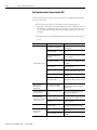
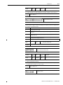
3-11
Sequence Input Signal (allocation)
Refer to the Chapter 5-2 for details of sequence input signal.
Type
Description
Mode
Reference
</SV-ON>
Servo-ON
If input is ON, the power is applied to the servo
motor, and if OFF, the power is cut off.
All
4-2
</A-RST>
Alarm reset
Resets the servo alarm status.
All
7-44
</G-SEL>
Gain group conversion
Use 2 group gain where the input is on, and use
existing gain where the input is off. Convert 2
types of gain groups.
All
6-27
</P-TL>
Limit forward torque
If signal is ON, limit forward torque by the
setting of [Pr-4.03].
All
</N-TL>
Limit reverse torque
If signal is ON, limit reverse torque by the
setting of [Pr-4.04].
All
<P-OT>
Prohibit forward
operation
If load mechanical part reaches the forward
limit, this prevents the motor from moving
further to that direction.
PSC
<N-OT>
Prohibit reverse
operation
If load mechanical part reaches the reverse
limit, this prevents the motor from moving
further to that direction.
PSC
</P-CON>
P/PI control conversion
Converts the speed controller from PI controller
type into P controller type.
Used to provide better response performance by
prohibiting the overshoot in transient response.
PSC
</C-SEL>
Control mode
conversion
Used to convert control mode when used as
combinational control mode.
Combinational Control
Mode Only
Refer to 5.6
</C-DIR>
</C-SP1>
</C-SP2>
</C-SP3>
</C-SP4>
Terminal speed
command
The rotation direction</C-DIR> and rotation
speed </C-SP1 to /C-SP4> of the motor are
determined by the above input in terminal speed
control mode. Rotation speed of </C-SP1 to /
C
C-SP3> is set in [Pr-2.05 to Pr-2.11]. Rotation
speed of </C-SP4> is set by analog speed
command voltage. </C-DIR> is used to change
motor roatation direction in speed control mode.
5-45
</Z-CLP>
Zero clamp
Disregard the input value if in speed control,
analog command value is smaller than the value
set at speed zero clamp level [Pr-5.04].
S
5-31
</INHIB>
Inhibit pulse command
Disregard position command pulse where the
signal is ON.
P
5-28
</ABS-DT>
Absolute Encoder Data
Transmission
Transmits absolute encoder data to host
controller through EA, EB when the signal is ON. P
7-32
</PCLR>
Clear position command, position feedback, and
position error.
P
5-21
/START
Control motor rotation start or stop by using
terminal signal in speed or terminal speed
control mode.
S, C
In position control mode, the 2nd electronic gear
parameters [Pr-3.05] and [Pr-3.06] are used when
input is ON. The basic electronic gear
parameters [Pr-3.01] and [Pr-3.02] are used when
input is OFF. Switch between two electronic
gear ratios.
P
/GEAR
5-41
7-2
6-21
5-33
5-23
Publication CSD3P-UM001E-EN-P — February 2008
3-12
Wiring
General Input Signal (fixed)
Power
Signal Name
Symbol
Function
Mode
Reference
External power
input
+24 [V]IN
As control power input for contact point
signal, +24 [V] power should be prepared
by users.
ALL
Signal Name
Symbol
Function
Mode
Reference
Emergency Stop
E-STOP
Connect and use an extra emergency stop
switch to quickly act upon emergency
situation,
ALL
3-17
Function
Mode
Reference
Receives position command by pulse
input. Can respond to both line drive
output and open collector output of host
controller.
P
Clears the position error.
P
Function
Mode
Reference
Receives analog speed command.
(-10 [V] to +10 [V])
S
5-28
Receives analog torque command.
(-10 [V] to +10 [V])
t
5-38
Symbol
Function
Mode
Reference
BAT+
Supplies the external battery power when
the absolute encoder is used.
ALL
7-27
Emergency Stop
Position Command
Signal Name
Symbol
PULS+
PULS-
Pulse command
SIGN+
5-9
SIGNPosition error
clear
PCLR+
Signal Name
Symbol
PCLR-
V-REF
Speed command
V-REF
input
SG
Torque
command input
T-REF
T-REF
SG
Battery Connection
Signal Name
Battery input
BAT-
Publication CSD3P-UM001E-EN-P — February 2008
Wiring
(CN1) Output Signal
3-13
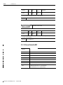
Sequence Output Signal (Allocation)
See Chapter 5-2 for details of sequence output signal.
Type
Description
Mode
Details
/P-COM (+, -)
(Positioning
Completion
detection)
It is ON when the position error is within the set value
of output width of position completion signal, [Pr-5.00],
P
/NEAR (+, -)
(Position approach
detection)
It is ON when the position error is within the setting
value of output width of position approach signal,
[Pr-5.01].
P
/V-COM (+, -)
(Speed coincidence
detection)
It is ON when error between speed command and motor
rotation speed is within the set value of output width of
speed coincidence signal, [Pr-5.02].
PSC
5-29
/TG-ON (+, -)
(Rotation
detection)
It is ON when the motor rotates at speeds higher than
the set value of rotation detection level, [Pr-5.03].
All
5-35
/T-LMT (+, -)
(Torque limit
detection)
It is ON when it reaches the set torque limit.
All
5-35
/V-LMT (+, -)
(Speed limit
detection)
It is ON when it reaches the set speed limit.
All
5-36
BK (+, -)
(Breaker control)
Signal for the control of brake mounted internally or
externally on the servo motor.
All
7-6
/WARN (+, -)
(Warning
detection)
It is ON if a servo warning is detected,
All
8-4
5-23
• In this manual, < > is applied to the names of sequence I/O signal.
NOTE
• ex) </SV-ON>, </P-COM>
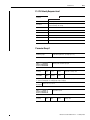
General Output Signal (fixed)
Alarm code
Signal Name
Symbol
AL1
Alarm code
AL2
AL3
AL-SG
Function
Mode
Reference
ALL
8-4
Upon servo alarm generation, it outputs
the types of the servo alarm with the 3-bit.
Maximum rating of open collector :
DC 30 [V], 20 [mA]
Publication CSD3P-UM001E-EN-P — February 2008
3-14
Wiring
Analog Monitor
Signal name
Analog Monitor
Output
Symbol
Function
Mode
Reference
AM-CH1
AM-CH2
Motor speed and torque, etc. are
displayed for monitoring.
ALL
7-25
AM-SG
Output range : -10 [V] to +10 [V].
Symbol
Function
Mode
Reference
ALL
7-21
Encoder signal
Signal name
EA+
EAEncoder Signal
Output
EB+
EBEC+
Displays multiplied encoder signal A, B, C
pulse in the form of line drive.
According to the parameter setting, the
drive can logically invert output of A, B
pulse.
ECAbsolute
Encoder S-pulse
PS+
PS-
Outputs the number of rotation by serial
data when the absolute encoder is used.
Symbol
Function
Mode
Reference
SALM+
It is displayed if the servo alarm is
generated.
ALL
7-25
Reference
Servo alarm
Signal name
Monitor Output
SALM-
Encoder Z-pulse display
Publication CSD3P-UM001E-EN-P — February 2008
Signal name
Symbol
Function
Mode
Encoder
Z-pulse
Z-PULSE +
It is displayed if Z-Pulse of the encoder is
detected.
ALL
Z-PULSE -
Wiring
(CN1) Input Circuit and
Interface
3-15
Describes the connection circuit for input from the host controller to the servo
drive.
Pulse Command Input Circuit
The drive receives the pulse output of host controller by position command in
position control mode.
• Host controller can output pulse in line drive or open collector type.
Select either of the two for use.
• Refer the Chapter 5-9 for the servo drive setting according to the
selection.
Input pin of CN1 that uses line drive and open collector output.
PULS +, PULS- (11, 12)
SIGN +, SIGN- (13, 14)
PCLR +, PCLR- (15, 16)
Line drive - Maximum allowable frequency 900 [kpps]
Line Drive
150[˟]
SN75174
Equivalent
4.7[k˟]
P
CN1
2.8[V]≤(H Level)-(L Level)≤3.7[V]
Host Controller
Open collector - Maximum allowable frequency 200 [kpps]
Vcc
Line Drive
R1
i
150[˟]
4.7[k˟]
P
VF
TR1
VF=1.5 to 1.8[V]
Host Controller
CN1
By using the example at the bottom, set the value of Pull Up resistor R1 so that
the input current i is within 7 [mA] to 15 [mA].
Vcc of the Host Controller
24 [V] ± 5 [%]
12 [V] ± 5 [%]
5 [V] ± 5 [%]
R1
2.2 [kW]
1 [kW]
180 [W]
Publication CSD3P-UM001E-EN-P — February 2008
3-16
Wiring
Maximum allowable frequency of host controller’s pulse command is
NOTE
• 900 [kpps] for the line drive,
• 200 [kpps] for the open collector,.
If the maximum allowable frequency is exceeded, “E.OvPUL” servo
alarm of position command pulse is generated.
Make sure the output of host controller does not exceed the maximum
allowable frequency.
Analog Voltage Input Circuit
The drive receives analog voltage output of the host controller with speed, speed of
torque control mode and torque command.
• Input impedance of speed and torque commands is about 5 [M ].
• Maximum allowable voltage range of input signal is -10 [V] to +10 [V].
Input pin of CN1 that uses analog voltage output of the host controller
Speed command V-REF, V-REF SG (19, 20)
Analog Input Circuit
Torque command T-REF, T-REF SG (21, 22)
Speed
Command
390[˟] (1/2W)
2[k˟]
1000:1
P
Torque
Command
390[˟] (1/2W)
+
T-REF
2[k˟]
1000:1
Host Controller
CN1
0[V]
Analog Input Circuit
12[V]
A/D
V-REF SG
Host Controller
Publication CSD3P-UM001E-EN-P — February 2008
+
V-REF
12[V]
P
T-REF SG
0[V]
A/D
CN1
Wiring
3-17
Sequence Input Circuit
Relay or open collector output of the host controller is used for the sequence input
circuit.
• Make sure that the input current i is within 7 [mA] to 15 [mA].
Relay Circuit
+24[V]IN
i
DC24[V] 50[mA]
or Higher
3.3[k˟]
P
CN1
Sequence Input Signal
(DI#1 to DI#7)
Host Controller
Open Colletor Circuit
i
DC24[V] 50[mA]
or Higher
3.3[k˟]
+24[V]IN
P
Sequence Input Signal
(DI#1 to DI#7)
Host Controller
CN1
Emergency Stop Signal
This drive has a built-in circuit for the emergency stop situation.
• To quickly respond to the equipment failure or dangerous situation, it receives
the emergency stop signal from #10 pin of CN1.
• Emergency stop input can be done by the relay contact output of host
controller and installing a separate switch.
#10 pin of CN1 assigned below is used as the input pin only for the emergency
stop.
Normal Operation
External Power 24[V]
E-STOP
E-STOP Switch
E-Stop
External Power 24[V]
E-STOP Switch
Install a host controller
or a separate switch.
+24[V] IN
+24[V] IN
E-STOP
1/2
10
1/2
10
CN
1
Publication CSD3P-UM001E-EN-P — February 2008
3-18
Wiring
NOTE
• If the emergency stop signal is input, “E.EStoP” servo alarm is
generated.
• Refer to the Chapter 8-4 more information on the servo alarm.
• If the emergency stop is released, reset the alarm by referring to
the Chapter 7-44.
NOTE
Publication CSD3P-UM001E-EN-P — February 2008
• You can check the status of emergency stop signal through the
monitor mode describe in the Chapter 7-50.
Wiring
(CN1) Output Circuit and
Interface
3-19
There are 3 types for the servo drive output circuits. Design the input circuit at
the host controller suitable for the each output circuit.
Line Drive Output
Output signal (EA+, EA-, EB+, EB-) that converted the encoder serial data
into 2 phase (A phase and B phase) pulse, zero point pulse signal (EC+, EC-)
and S phase rotation amount signal (PS+, PS-), are output to line drive circuit.
It is used to configure the position control loop from the host controller.
Receive the pulse signal with the line receiver circuit in the host controller.
Set R1 value to 330 [Ω].
R1
P
CN1
0[V]
Host Controller
Open collector output
The servo alarm code output signal is an open collector output circuit. The
figure below shows the connection in order of photo coupler, line receiver, and
relay circuit.
• The maximum allowable voltage of the open collector output circuit is
DC 30 [V], and the allowable current is 20 [mA].
DC 5 to 12 [V]
Photo-Coupler
P
0[V]
CN1
0[V]
Host Controller
DC 5 to 12 [ V ]
Line Receiver
P
0[V ]
CN1
0[V]
Host Controller
DC 5 to 12 [ V ]
Relay
P
CN1
0[V]
0[V]
Host Controller
Publication CSD3P-UM001E-EN-P — February 2008
3-20
Wiring
Photo coupler output
Servo alarm, sequence output signal and encoder Z-pulse signal output are the
photo coupler output circuits.
Connection to the relay circuit of the host controller.
DC 5 to 24 [V]
Relay
P
0[V]
CN1
Host Controller
Connection to the line receiver circuit of the host controller.
DC 5 to 12 [V]
Line Receiver
P
CN1
Publication CSD3P-UM001E-EN-P — February 2008
0[V]
Host Controller
Wiring
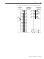
Encoder Wiring (CN2)
3-21
Pin Arrangement of (CN2)
The table below shows the pin arrangement for each encoder.
DRIVE
PIN
NO.
MOTOR
FUNCTION
CSM
CSMT
CSMR
CSMS/D/H/K
RSMS/D/H
RSMF/K/L
RSMQ
RSMZ
CSMT
CSMR
RSMQ
RSMZ
RSMS/D
RSMH/F
RSMK/L
9 wire
INC.
15 wire
INC.
ABS.
9 wire
INC.
ABS.
9 wire
INC.
15 wire
INC.
ABS.
17bit
Serial
Abs./Inc.
17bit
Serial
Abs./Inc.
E0 [V]
8
14
14
11
14
G
G
G
8
G
3
A
1
1
1
1
1
A
A
A
4
/A
2
2
2
2
2
B
B
B
5
B
3
3
3
3
3
C
C
C
6
/B
4
4
4
4
4
D
D
D
7
C
5
5
5
5
5
E
E
E
8
/C
6
6
6
6
6
F
F
F
7
7
11
K
K
4
K
9
9
8
12
L
5
L
1
2
9
10
U
11
RST
R
12
13
/U
8
14
V
9
M
15
/V
10
N
16
W
11
P
17
/W
12
R
18
BAT+
11
7
T
1
T
19
BAT-
12
8
S
2
S
20
E5 [V]
Frame
FG
L
7
13
13
10
13
H
H
H
7
H
9
15
10
15
12
10
15
J
J
J
3
J
Publication CSD3P-UM001E-EN-P — February 2008
3-22
Wiring
(CN2) Terminal Type
The table below shows the terminal type and specifications of the encoder
cable.
<Encoder Cable>
CON A.
CON B.
Connect this to CN2
of the servo drive
Connect this to the encoder
cable of the servo drive
Connector CON A for connection to CN2 of servo drive.
One type regardless of motor model and encoder.
Model Number
Manufacturer
10120-300VE
10320-52A0-008
3M
Connector CON B for connection to the encoder cable of servo motor.
Classification
CSM, CSMT, CSMR
RSMZ, RSMQ
RSMS, RSMD, RSMH,
RSMF, RSMK, RSML
CSMK
CSMT, CSMR
Publication CSD3P-UM001E-EN-P — February 2008
Model Number
9 wire Inc.
Serial Absolute
Serial Inc.
172161-1
15 wire Inc.
172163-1
Absolute Type
172163-1
9 wire Inc.
171162-1
Absolute.
172163-1
Manufacturer
AMP
9 wire Inc.
15 wire Inc.
DMS 3108B20-29S or
DMS 3106B 20-29S
DDK
Compact Absolute
NOTE
• Do not connect FG of servo drive to host controller if GND and FG
are common, or if there is no separate FG,
NOTE
• CSMG motor has a gear attached to CSM motor. Other motor
specifications are same.
Wiring
3-23
Encoder Signal Process
1. Incremental encoder (9 wire Inc.) connection of CSM, CSMT/R motors
CSD3
CN1
CN2
A 3
29 EA
Encoder
1
P
2
/A
4
30 /EA
B
5
31
/B
6
32 /EB
C
7
33
/C
8
34 /EC
3
P
4
5
P
6
E5[V] 20
7
P
8
E0[V] 1
FG 12
9
Host Controller
P
EB
P
EC
P
27
SG
0[V]
50
FG
0[V]
2. Absolute encoder connection of CSM, CSMT/R motoers
CSD3 Plus
encoder
1
2
P
3
4
P
5
6
P
7
8
P
9
11
12
P
13
14
P
controller
CN2
CN1
A
3
29
EA
/A
4
30
/ EA
B
5
31
EB
/B
6
32
/ EB
C
7
33
EC
/C
8
34
/ EC
RX
10
35
PS
/ RX
13
36
/ PS
RST
11
BAT +
18
BAT -
19
27
SG
0 [ V]
E 5 [ V ] 20
49
BAT +
E0 [ V] 1
25
BAT -
Serial I/F circuit
P
Up/Down
counter
P
P
Serial I/F circuit
P
0[ V]
P
DC 2.8 ~ 4.5 [ V]
15
FG
FG
Publication CSD3P-UM001E-EN-P — February 2008
3-24
Wiring
3. Incremental encoder (15-wire Inc.) connection of CSM, CSMT/R
motoers
CSD3 Plus
encoder
1
2
P
3
4
P
5
6
P
CN1
A
3
29
EA
/A
4
30
/ EA
B
5
31
EB
/B
6
32
/ EB
C
7
33
EC
/C
8
34
/ EC
U
10
35
PS
/U
13
36
/ PS
V
14
/V
15
W
16
/W
17
27
SG
0 [ V]
E 5 [ V ] 20
49
BAT +
E0 [ V] 1
25
BAT -
7
8
P
9
10
P
11
12
P
13
14
P
controller
CN2
Serial I/F circuit
P
Up/Down
counter
P
P
Serial I/F circuit
P
0[ V]
P
DC 2.8 ~ 4.5 [ V]
FG
15
FG
4. Incremental encoder (9 wire Inc.) connection of RSMS/D/F/H/K/L
motors
CSD3 Plus
encoder
A
B
P
C
D
P
E
F
P
controller
CN2
CN1
A
3
29
EA
/A
4
30
/ EA
B
5
31
EB
/B
6
32
/ EB
C
7
33
EC
/C
8
34
/ EC
Serial I/F circuit
P
Up/Down
counter
P
P
Serial I/F circuit
E 5 [ V ] 20
H
G
J
Publication CSD3P-UM001E-EN-P — February 2008
P
E0[ V] 1
FG
27
SG
0[ V]
FG
0[ V]
Wiring
3-25
5. Incremental encoder (15 wire Inc.) connection of RSMS/D/F/H/K/L
motors
CSD3 Plus
encoder
A
B
P
C
D
P
E
F
P
K
L
P
M
N
P
P
R
P
J
CN1
A
3
29
EA
/A
4
30
/ EA
B
5
31
EB
/B
6
32
/ EB
C
7
33
EC
/C
8
34
/ EC
U
10
/U
13
V
14
/V
15
W
16
/W
17
Serial I/F circuit
P
Up/Down
counter
P
P
Serial I/F circuit
E 5 [ V ] 20
H
G
controller
CN2
P
E0 [ V] 1
FG
27
SG
0 [ V]
FG
0[ V]
Publication CSD3P-UM001E-EN-P — February 2008
3-26
Wiring
6. Absolute encoder connection of RSMS/D/F/H/K/L motors
CSD3 Plus
encoder
CN2
A
B
P
C
D
P
E
F
P
K
L
P
R
P
J
Publication CSD3P-UM001E-EN-P — February 2008
3
29
EA
/A
4
30
/ EA
B
5
31
EB
/B
6
32
/ EB
C
7
33
EC
/C
8
34
/ EC
U
10
/U
13
RST
11
Serial I/F circuit
P
Up/Down
counter
P
P
Serial I/F circuit
WT
BATA
AT
19
E 5 [ V ] 20
H
G
A
BAT+ 18
T
S
controller
CN1
P
E0 [ V] 1
FG
27
SG
0 [ V]
FG
0[ V]
Wiring
3-27
7. Serial encoder connection of RSMS/D/F/H/K/L motors
CSD3 Plus
encoder
K
L
P
H
G
P
T
S
P
controller
CN2
CN1
SD +
10
29
EA
SD -
13
30
/ EA
E 5 [ V ] 20
31
EB
E 0 [ V] 1
32
/ EB
BAT +
18
33
EC
BAT -
19
34
/ EC
35
PS
36
/ PS
27
SG
0 [ V]
49
BAT +
25
BAT -
Serial I/F circuit
P
Up/Down
counter
P
P
Serial I/F circuit
P
0 [ V]
P
DC 2 . 8 ~ 4 . 5 [ V ]
J
FG
FG
Publication CSD3P-UM001E-EN-P — February 2008
3-28
Wiring
8. Absolute encoder connection of RSMQ/Z motors
CSD3 Plus
encoder
CN1
A
3
29
EA
/A
4
30
/ EA
B
5
31
EB
/B
6
32
/ EB
C
7
33
EC
/C
8
34
/ EC
BAT + 18
35
PS
BAT -
19
36
/ PS
9
RST
11
10
FG
1
2
P
3
4
P
5
6
P
7
8
P
11
12
P
13
14
15
Publication CSD3P-UM001E-EN-P — February 2008
controller
CN2
P
RX
10
27
SG
0 [ V]
/ RX
13
49
BAT +
E 5 [ V ] 20
25
BAT -
Serial I/F circuit
P
Up/Down
counter
P
P
Serial I/F circuit
P
0[ V]
P
DC 2 .8~ 4 .5[ V]
E0 [ V] 1
FG
FG
Wiring
3-29
9. Incremental encoder (9-wire Inc.) connection of RSMQ/Z motors
CSD3 Plus
encoder
1
2
P
3
4
P
5
6
P
11
12
CN1
A
3
29
EA
/A
4
30
/ EA
B
5
31
EB
/B
6
32
/ EB
C
7
33
EC
/C
8
34
/ EC
35
PS
36
/ PS
E 5 [ V ] 20
10
P
controller
CN2
27
SG
0 [ V]
49
BAT +
25
BAT -
Serial I/F circuit
P
Up/Down
counter
P
P
Serial I/F circuit
P
0[ V]
P
DC 2 .8~ 4 .5[ V]
E0 [ V] 1
FG
FG
Publication CSD3P-UM001E-EN-P — February 2008
3-30
Wiring
10. Serial encoder connection of RSMQ/Z motors (Absolute, Incremental)
(18 and 19 not necessary for Incremental)
CSD3 Plus
encoder
4
5
P
7
8
P
1
2
P
controller
CN2
CN1
SD +
10
29
EA
SD -
13
30
/ EA
E 5 [ V ] 20
31
EB
E 0 [ V] 1
32
/ EB
BAT +
18
33
EC
BAT -
19
34
/ EC
35
PS
36
/ PS
27
SG
0 [ V]
49
BAT +
25
BAT -
Serial I/F circuit
P
Up/Down
counter
P
P
Serial I/F circuit
P
0 [ V]
P
DC 2 . 8 ~ 4 . 5 [ V ]
3
Publication CSD3P-UM001E-EN-P — February 2008
FG
FG
Wiring
Battery Specifications
The figure below shows the specifications of battery connected to BATT of
servo drive.
MOLEX 5264-02
RED
+
+ RED
- BLACK
-
YELLOW TUBE
BLACK
12
Tube
+
Soldering
Less than 14.5
Wiringthe Battery (BATT)
3-31
DC 3.6V
AAA
-
Soldering
Spot Welding
Spot Welding
Wiring the Battery (BATT)
The figure below shows how to connect the battery to BATT of the servo
drive.
<2>
<1>
Procedure
1. Prepare a battery according to the specifications.
2. Open the battery cover.
3. Push it to the end in the direction of <1>.
4. Connect the connector in the direction of <2>.
5. Close the battery cover.
6. If you follow the battery specifications, the polarity coincides.
Publication CSD3P-UM001E-EN-P — February 2008
3-32
Wiring
General Articles Wiring
This part describes wiring to implement optimum performance of the servo
drive in wiring and noise.
Precautions
Electric Circuit
• Use a thick wire as earth wire if possible.
• Class 3 grounding is recommended. (Recommendation: grounding resistance
lower than 100Ω).
• Only 1 point must be grounded.
• Select ground phase and ground point considering the power conditions of
installation area. If the power is supplied by the ground phase, wire it so that L2
of AC main power input terminal (L1, L2, L3) becomes the ground phase.
• Use noise filter for the main power and control power.
• Electric circuit wiring and signal circuit wiring should be apart as much as
possible. (30 [cm] or more)
• Do not use same power with the electric ARC welding machine or discharge
processor equipment.
• The earth wire of the servo motor must be connected to the grounding
terminal of the drive. In addition, ground the grounding terminal of the drive.
• If the wiring is inside the metal pipe, ground the pipe with class 1 grounding.
Signal Circuit
• The host controller should be installed as closely as possible to the drive, and
the noise filter must be used.
• CN1 (I/O signal connector) and CN2 (encoder cable) should be twist pair wire
and batch shield wire. (Refer to the appendix for the Samsung's standardized
parts.)
• Note that the signal circuit wire is very thin, thus pay attention when handling
it.
• If the noise is generated at command input cable, ground 0 [V] line (SG) of the
input line before the usage.
Others
• Use the breaker or fuse for wiring to protect the servo drive.
• Make sure there is no continuous bending and stress to the wire.
• Use noise filter in radio noise.
• If used around residential area or the radio disturbance is concerned, install a
noise filter on the input side of power line.
• As the drive is for industrial use, there are no measures for radio disturbance.
• Attach a surge absorption circuit to the relay, solenoid, and coil of the magnetic
contactor.
Publication CSD3P-UM001E-EN-P — February 2008
Wiring
3-33
Capacity of the Drive and Fuse
The table below shows the capacity of servo drive and fuse.
Capacity
CSD3-
Power Capacity per 1
Drive
[kVA]
50 [W]
A5BX2
0.25
100 [W]
01BX2
0.40
200 [W]
02BX2
0.75
400 [W]
04BX2
1.2
8
1 [KW]
10BX2
2.3
7
1.5 [KW]
15BX2
3.2
10
Drive type
Power
Single phase 220V
MCCB or Fuse
Power Capacity
[Arms]
4
3 phase 220V
The fuse capacity is the value when 100 [%] load is applied. When selecting the MCCB (breaker for
wiring) or fuse capacity, select the fuse capacity considering the load ratio.
Cut-off features : 200 [%]-2 seconds or more. 700 [%]- 0.01 second or more.
NOTE
The high -speed cut-off fuse can not be used. As the power of the
drive is condenser input type, the fuse may be blown even during a
normal situation if the high-speed cut-off fuse is used
Publication CSD3P-UM001E-EN-P — February 2008
3-34
Wiring
Noise Protection
The high-speed switching device and microprocessor are used at the main
circuit of the servo drive. Thus, switching noise is affected by the connection
and grounding methods. Use the proper wiring and grounding method to
prevent any affects from the noise.
Use a wire of 3.5 [mm2] or thicker for the earth wire.
LINE FILTER
1
P
P
LINE
FILTER
2
P
AV
R
Ralay Sequence Circuit
Signal Generating Circuit
CSD3 SERVO DRIVE
L
1
L
2
L
3
L1C
CN1
U
Servo Motor
L2C
V
W
Heat Sink
CN2
P
G
M
Ground Plate
Earth Grounding
One Point Grounding<Class 3 Grounding or Higher>
Extra caution is required when wiring the noise filter. The following figure
describes precautions when wiring the noise filter. If the wiring is wrong, the
performance of the noise filter falls.
Publication CSD3P-UM001E-EN-P — February 2008
Wiring
3-35
• Separate the input and output wiring of the noise filter and do not tie
up them together.
Primary and Secondary
Interference
Secondary
Primary
Secondary
Primary
Filter
Filter
Primary and Secondary
Interference
Primary
Secondary
Secondary
Separation of
Circuit
Filter
Secondary
Primary
Secondary Primary
Filter
Primary
Separation of
Circuit
• Earth wire of the noise filter should be wired in distance to the
output wire and do not put other signal lines and earth wire in a same
duct and tie up them together.
Primary
Secondary
Secondary
Filter
Secondary
Primary
Secondary
Primary
Filter
Primary
Publication CSD3P-UM001E-EN-P — February 2008
3-36
Wiring
• Earth wire of noise filter should be solely attached in the earth plate.
Do not connect the earth wire of the noise filter to other earth wire
together.
Primary
Secondary
Secondary
Filter
Secondary
Primary
Secondary
Primary
Filter
Primary
• If there is noise filter inside the case (panel), connect all of the earth
wires and earth wires of other equipment inside of the case to the
grounding plate. And then, ground them.
Secondary
Primary
Filter
ٻ
Publication CSD3P-UM001E-EN-P — February 2008
Wiring
3-37
Wiring when Using Several Drives
This is an example of wiring when connecting several drives.
• Connect the alarm output (SALM) signal of each servo drive in a
series and run Relay 1 to detect the alarm. Normally, SALM+ and
SALM- are interconnected, and with 24 [V] supplied to Relay1, the
servo drive runs normally.
• If the servo alarm is generated, 24 [V] supplied to Relay1 is cut off.
1MCCB
NOISE
FILTER
1MC
1MC
Relay
SW1 OFF
SW2 ON
SUP
1
Alarm Display Lamp
1
1MC
+24[V]
L1
L2
L3
CN1
SALM+ 45
Relay 1
SALM- 46
L1C
+24[V]IN 1/2
+24[V]
L2C
E-STOP
10
0[V]
L1
L2
L3
CN1
SALM+ 45
SALM- 46
L1C
+24[V]IN 1/2
+24[V]
L2C
E-STOP
10
0[V]
L1
L2
L3
CN1
0[V]
SALM+ 45
SALM- 46
L1C
+24[V]IN 1/2
+24[V]
L2C
E-STOP
10
0[V]
Publication CSD3P-UM001E-EN-P — February 2008
3-38
Wiring
Connection to Peripheral Equipment
y z {
AC 220 [V] Power
MCCB
Breaks the circuit if large
inruch current flows on
power line.
Noise Filter
Removes the noise
from the power line.
Regenerative
Resistor
Magnetic
Contactor
ih{{
Battery
sX
sY
sZ
sXj
sYj
u
juX
Host
Controller
wX
wY
iX
iY
|
}
~
Magnetic Contactor
for the Motor Break
Control
juY
Motor Cable
Encoder Cable
Brake Cable
Motor Brake
Control Power
Motor Break
Control
Publication CSD3P-UM001E-EN-P — February 2008
juZ
Servo Motor
Portable Operator
Chapter
4
Operator, Basic Setting and Startup
Introduction
1
This chapter introduces the operator mounted on the servo drive. In addition,
it describes the basic setting of servo drive, and also an example for simple
startup.
Topic
Page
Introduction
4-1
Before You Begin
4-2
Operator
4-6
Basic Setting
4-13
Startup
4-22
Publication CSD3P-UM001E-EN-P — February 2008
4-2
Operator, Basic Setting and Startup
Before You Begin
About Servo-ON Signal
This part describes Servo-ON signal for the control of the servo drive.
What is Servo-ON?
Audio or TV can select and play music and display channel that the users want
from the moment the power switch is on.
However, the servo drive cannot run servo motor by simple applying the
power. To complete load the system and use the servo drive, Servo-ON signal
from the host controller is required.
Servo-ON signal should be applied and maintained from the host controller
for the servo drive to run the motor. In servo -OFF status, it cannot run the
motor.
Servo-OFF and Servo-ON
Servo-OFF Status
Servo-ON Status
• If the servo-ON signal is not applied after the • If the servo-ON signal is applied from the
host controller, the drive starts to apply
power application, it is same as the servo
voltage to the motor. At this time, if there is
driver and motor being separated completely.
no motor run command, the drive maintains
• This is a ready status to run the motor.
the motor stopped.
Power
Power
/SV-ON
Input of commands such as position, speed regarding servo-ON status and motor run.
• If the motor run command is input while the servo-ON signal of the host controller is maintained,
the drive can run the motor according to the command.
Power
/SV-ON
Input of command
such as position,
speed.
Motor
< Rotation >
Publication CSD3P-UM001E-EN-P — February 2008
Operator, Basic Setting and Startup
4-3
Servo-ON signal of the host controller and running the automobile
The following describes the servo drive in relation to the transmission of the
automobile.
Host
Controller
Apply power
to the drive
Receive servoON signal.
Receive command
such as position, speed.
Motor
Rotates.
Operator
Start
automobile.
Receive servoON signal.
Receive command
such as position, speed.
Motor
Rotates.
• As the transmission of the automobile should be positioned at 'D' to
start the automobile, the drive can be run only when the servo-ON of
the host controller is maintained.
• Commands to run the motor such as the position, speed of host
controller are invalid in Servo-OFF status.
In this manual, the Servo-ON signal is indicated as shown below.
Servo-ON, </SV-ON>
Servo -OFF
Servo-ON signal input
Servo-ON signal from host controller is received through the sequence input
signal of CN1. Refer to the Chapter 5-2 for the sequence I/O signals.
Servo drive's own Servo-ON
If the servo drive runs the motor without a command from the host controller
as in the operation mode (run-00), (run-01), the drive make itself Servo-ON
for the operation.
• Refer to the Chapter 7-35 for the operation mode (run-00) to (run-02).
• In addition, the operation mode (run-00) is described in the Chapter
4-22 Startup.
• (run-00),(run-01),(run-07),(run-08),(run-10),(run-12) are not operated in
Servo-ON status.
Alarm occurrence and Servo-ON status
If servo alarm is occurred by the self-diagnosis function of the drive while the
Servo-ON signal is applied to the drive, the drive make itself Servo-OFF to
stop the motor and displays the contents of servo alarm. Users should inspect
the contents of servo alarm, take necessary action, and reset the alarm (Refer
to the Chapter 7-44). At this time, if an appropriate action against the servo
alarm is taken and the servo-ON signal of host controller is maintained, the
drive returns to servo-ON status at the moment that alarm is reset.
Publication CSD3P-UM001E-EN-P — February 2008
4-4
Operator, Basic Setting and Startup
• Refer to the Chapter 8-6 for the information of the servo alarm.
• All parameter setting after Chapter 4-1 should be done for the
Servo-ON status and Servo-OFF status.
NOTE
• In this manual, ‘the servo drive status’ means whether the servo
drive is in servo-ON status or servo-OFF status.
Table for Parameter Setting
This manual uses the following table for parameter description.
Parameter Name
Parameter Setting Window Initial Value
Setting Value
0
1
Applicable Mode
ALL
Others
Servo-OFF > Setting > Power Off & On > End
Table Description
• Parameter at the top-left side shows the parameter being described.
• The setting window on the right of the parameter, is entered when the
ENTER key is pressed. The parameter must be set from the digit in
black color and the initial value shows the initial value of the parameter.
• It is classified into a parameter selected among already set values
(“selected parameter”) and a parameter, which the users give appropriate
values. The selected parameter, as shown in the example above, displays
both parameter and setting window, and the latter parameter displays
only the parameter and not the setting window.
• <Setting value> Describes the value selectable by the user and the
selected value.
• <Applicable mode> Alphabetically displays the corresponding control
mode in setting parameter, and displays (ALL) if all are included.
Alphabets display each mode
Mode
Position mode
Speed mode
Torque mode
Multi-step speed mode
Display
P
S
t
C
• Combinational control mode indicates the alphabets of two modes,
combined in a row.
Publication CSD3P-UM001E-EN-P — February 2008
Operator, Basic Setting and Startup
4-5
• ex) speed + position mode (SP), torque-speed mode (tS).
• <Others> Normally, as described in an example of automobile in the
Chapter 4-2, the driver cannot manipulate parking brake of a running
automobile, and the servo drive also should be divided into Servo-ON
status and Servo-OFF status when setting the parameter.
Others
Description
Setting > End
Set regardless of the drive status.
Servo-OFF > Setting > End
Set it in Servo–OFF status.
Servo-OFF > Setting > Power Off & On >
Completion
Set it in Servo-OFF status, and apply the power again.
Publication CSD3P-UM001E-EN-P — February 2008
4-6
Operator, Basic Setting and Startup
Operator
Name and Function of Each Part
The servo drive has a built-in operator for various status displays, parameter
setting, operation command, and monitoring.
• Displays various contents with six 7-segment LED display.
• Distinguish the type of the servo drive according to the front design of
the operator.
• Provides all key manipulation function without a separate external
operator.
• The following figure shows the front side of the operator on the servo
drive.
1
7
2
All-In-One
6
MODE
SET
3
ENTER
4
5
CHARGE
Publication CSD3P-UM001E-EN-P — February 2008
POWER
No.
Name
Function
1
7-Segment LED Display
Displays the status with 6-digit 7-segment LED display,
sets parameter, commands operation and displays
monitoring.
2
MODE/SET Key
Enters display mode shift and parameter setting value.
3
ENTER key
Enters into each window after changes the display mode.
Completes setting and exits from it.
4
Control Power Check Lamp
Checks if the control power is applied.
5
Main Power Check and
Discharge Check Lamp
Checks if the main power is applied, and if the capacitor of
the main circuit is discharged after the main power cut-off
6
Top, Bottom, Left/Right Key
Moves the digit of 7-segment LED display and functions as
the UP/DOWN of the number.
7
Drive Type
There are two types: All-In-One and Position-Control-Only.
Operator, Basic Setting and Startup
4-7
Icons for the Key Buttons
Describes the functions and icons of the key buttons.
• Icon is used in description throughout the manual. Thus, be fully aware
of the shape, name and function of icons.
Icon
Name
Up
Down
Left/
Right
Function
Icon
Increases and
decreases the value.
Press and hold this
icon to continuously
increase/decrease the
value.
Use this when setting
the value.
Shifts the digits.
Name
Function
Direction
Key
Used to indicate
up, down, left, right
keys altogether.
MODE/
SET Key
Changes the mode.
Saves the setting
value.
ENTER
Key
To enter/exit each
setting window
after changing the
mode.
Black key button represents that it is pressed.
Structure of the Entire Mode
As shown in the figure below, the servo drive is divided into 4 types of control
modes:
• The mode displayed after the power ON is the status display mode.
• Mode is changed whenever the MODE/SET key is pressed.
• Be fully aware of the following 4 mode types and read the following.
Power
Connection
Status Display Mode
Operation Mode
Status Display Mode
Monitor Mode
Publication CSD3P-UM001E-EN-P — February 2008
4-8
Operator, Basic Setting and Startup
• All parameter setting after Chapter 4-1 should be done for the
Servo-ON status and Servo-OFF status.
NOTE
• In this manual, ‘the servo drive status’ means whether the servo
drive is in servo-ON status or servo-OFF status.
Status Display Mode
This section describes contents of the status display mode.
• The figure below is an example of display for the description of the
status mode.
• The display on the right is separated for the convenience of description.
• Refer to the table below for the meaning of each display.
Row
Display 1
Row
Display 2
Control Mode
Control
Mode
Status
Point Display
Row
Display 3
Basic Control Mode
Combinational Control Mode
Display
Display
Description
Description
Position mode
Speed + position mode
Speed mode
Torque + speed mode
Torque mode
Torque + position mode
Multi-step speed
mode
Multi-step speed + position
mode
Multi-step speed + speed
mode
Multi-step speed + torque
mode
• Displays control mode in use. In Servo-ON status (in operation), the display of the
control mode flickers.
• In combinational control mode, it performs two types of selected mode
simultaneously for the operation. And at this time, the display of the current mode
is flickered. If the mode is changed, the display of new mode flickers, and the
previous mode does not.
Publication CSD3P-UM001E-EN-P — February 2008
Operator, Basic Setting and Startup
Display
Description
SERCOS
Network option
DeviceNet
Network option
4-9
Displays corresponding option upon the use of the
network option.
Refer to the Chapter 1-6 for the network option.
BASE-BLOCK means the preparation for the operation in Servo-OFF
status.
Status
Displays that it is running.
Displayed when forward operation prohibiting signal is input.
Displayed when reverse operation prohibiting signal is input.
• Displays corresponding character upon servo warning.
• Refer to the chapter 8 for details of the servo warning.
Description
Point
Display
It is on if the power is applied.
Refer to the reference pages on the right for more information on the row
display.
Description
Reference
When using as a position mode, if the difference between load position
and position command is smaller than [Pr-5.00] value, the servo drive
can display (</P-COM> position completion detection) signal. It is on
when </P-COM> signal is displayed.
5-23
When using as a speed mode, if the difference between motor speed
and speed command is smaller than [Pr-5.02] value, the servo drive can
display (</V-COM> speed coincidence detection) signal. It is on when
</V-COM> signal is displayed.
5-29
Row
Display 2
When the rotation speed of the motor is higher than the setting value of
rotation detection level [Pr-5.03], the servo drive can display (</TG-ON>
rotation detection) signal. It is on when </TG-ON > signal is displayed.
5-35
Row
Display 3
It is on when Z-pulse output of the encoder is detected.
Row
Display 1
Overview of the Parameter Setting Mode
This section includes brief explanation of the parameters in parameter setting
mode.
• The Parameter sets and saves various functions to make drive suitable
for equipment.
Publication CSD3P-UM001E-EN-P — February 2008
4-10
Operator, Basic Setting and Startup
• There is a parameter that can be always set regardless of the status of the
drive, and those that must be in certain status of the drive when setting
them. Be careful to set parameter in reference to the contents in the
Chapter 4-2.
• The table below is to aid the understanding of parameter group.
• The contents related to parameter setting are described in details in
Chapter 5, 6, 7, 8 and the Appendix along with the functional
description of the servo drive.
To
From
Parameter Group
Parameter Group Description
Group 0
0.00 to 0.14
15
User parameter related to basic setting and I/O signal
Group 1
1.00 to 1.15
16
User parameter related to gain and gain tuning
Group 2
2.00 to 2.13
14
User parameter related to speed control mode
Group 3
3.00 to 3.06
7
User parameter related to position control mode
Group 4
4.00 to 4.06
7
User parameter related to torque control mode
Group 5
5.00 to 5.14
15
User parameter related to supplementary function
Overview of the Monitor Mode
This section includes brief explanation of the parameters in monitor mode.
• Displays several numerical data generated as the motor is controlled by
the drive.
• The contents of the monitor mode can be checked regardless of the
status of the drive.
• Be fully aware of the numbers and units displayed in monitor mode
shown in the table below and refer to it when using the servo drive.
• The table below shows the brief contents of each item in the monitor
mode.
To
From
Publication CSD3P-UM001E-EN-P — February 2008
Monitor Contents
Item (Unit)
Monitor Contents
Item (Unit)
Monitor Contents
Item (Unit)
00
Speed feedback [rpm]
07
Position command pulse
frequency [kpps]
14
Torque command offset
[mV]
01
Speed command [rpm]
08
Electrical angle [°]
15
I/O status
Operator, Basic Setting and Startup
4-11
02
Speed error [rpm]
09
Mechanical angle [°]
16
Alarm history
03
Torque command [%]
10
Accumulated load rate of
regenerative resistor [%]
17
Firmware version
04
Position feedback
[pulse]
11
DC Link voltage [V]
18
Motor & Encoder Type
05
Position command
[pulse]
12
The number of rotation
data of absolute encoder
19
Analog speed command
voltage [0.01V]
20
Analog torque
command voltage
[0.01V]
21
Drive rated output
22
Absolute encoder
1-time rotation data
23
encoder feedback
counter
06
Position error [pulse]
NOTE
13
Speed command offset
[mA]
• The item of the monitor mode, whose value is more than 6 digits,
is not displayed at once by the 6-digit 7-segment LED display.
• Refer to the Chapter 7-50 for details on how to check such items.
Overview of the Operation Mode
This section includes brief explanation of the parameters in operation mode.
• The motor can be run in operation mode.
• Each item provides a special function, which can be used.
• Just as in the parameter setting mode, there is a status where the
operation is possible/impossible according to the status of the servo
drive, during the use of the operation mode. Refer to the Chapter 7-35
for details of operation mode.
• The table below shows the brief functions of each item in the operation
mode.
To
From
Item
Operation
Item
Operation
00
Jog operation
07
Adjustment of Current feedback
offset
01
Off-line auto tuning
08
Alarm reset
02
Homing
09
Alarm history clear
03
Auto adjustment of the Speed
command offset
10
Absolute encoder reset
Publication CSD3P-UM001E-EN-P — February 2008
4-12
Operator, Basic Setting and Startup
04
Auto adjustment of the torque
command offset
11
2-group gain storing
05
Manual adjustment of the speed
command offset
12
Parameter initialization
06
Manual adjustment of the torque
command offset
NOTE
Publication CSD3P-UM001E-EN-P — February 2008
Refer to the Chapter 7-35 for details of operation mode and key button
manipulation.
Operator, Basic Setting and Startup
Basic Setting
4-13
This section includes the introduction of the control mode and the basic
setting.
Overview of the Basic Setting
Basic setting must be done before using the servo drive.
1. Other parameters can be set after the basic setting.
2. The basic setting is possible only after connecting the control power of the
servo drive.
3. After all setting three types of basic setting, reapply the power.
4. The setting values of the basic setting are saved even if the power is cut off
or parameter is initialized by [run-12] function of the operation mode.
5. To change basic setting value, change it directly from corresponding
parameter and reapply the power.
As shown below, the basic setting uses three parameters to set 3 types.
Basic Setting Parameter
Setting
1
Control mode (optional) setting
2
Motor setting
Motor type setting
Motor capacity (rated output) setting
Encoder type setting
3
Main power input (optional) setting
• The key button manipulation flow chart is provided in the description
of the basic setting to aid the understanding of the key buttons. While
performing the basic setting, get accustomed to key button
manipulation. Key button manipulation flowchart is not described after
Chapter 5.
The following figure is an example of the nameplate attached to the motor.
• Before performing basic setting, be sure to check the following three
contents of the model name.
Publication CSD3P-UM001E-EN-P — February 2008
4-14
Operator, Basic Setting and Startup
• Before mounting a motor to the equipment, check the model name of
the motor in advance. Depending on the motor type, the motor may be
mounted in such direction that the nameplate is not visible.
Check the model name on the
motor nameplate.
Select a Motor
<Example of Model Name>
y z t
Motor Type
W X i h X h u r y
Rated Output
Encoder Type
GG
Control Mode Setting
Control Mode Type
As in the table below, there are 4 kinds of basic control modes and 6 kinds of
associated control modes.
• The drive has another drive exclusively for the position control. For this
drive, there is no need for a separate control mode selection. (Refer to
the Chapter 1-7)
• Combinational control mode cannot be used by combining more than 3
types. Make sure to combine two types only.
• The table below shows the control mode types. Refer to the chapter 5
for function for each control mode.
Basic Control Mode
Associated Control Mode
Display
Display
Description
Description
Position mode
Speed + position mode
Speed mode
Torque + speed mode
Torque mode
Torque+ position mode
Multi-step mode
Multi-step speed + position mode
Multi-step speed + speed mode
Multi-step speed + torque mode
Publication CSD3P-UM001E-EN-P — February 2008
Operator, Basic Setting and Startup
4-15
Control Mode Setting Method
Describes control mode setting method focusing on the key button
manipulation.
• Apply the power and set it as shown in the flowchart below.
Flowchart of the Control Mode Setting
Status Display Mode
Select Parameter Setting
mode by MODE/SET key.
Press ENTER Key and
Enter into the Setting
Window.
Using the direction key, create a control mode to set
Displays control mode by UP-DOWN key.
Shift position by LEFT-RIGHT key.
An alphabet representing each mode is displayed.
Multi-step speed
control
Torque Control
Speed Control
Position Control
Control mode selection completion.
Press MODE/SET key to save it.
The setting window blinks and it is saved.
To complete the setting, Turn power off and on again.
Publication CSD3P-UM001E-EN-P — February 2008
4-16
Operator, Basic Setting and Startup
Combinational Control Mode Setting
Combinational control mode should be set as below.
Associated Control Mode
Display
Speed + position control
(SP)
Torque + speed control
(TS)
Torque + position control
(TP)
Multi-step speed + position control
(CP)
Multi-step speed + speed control
(CS)
Setting Window Display
Precautions
The following are the precautions in setting associated control mode.
• Combinational control mode cannot be used by combining more than 3
types. Make sure to combine two types only.
• If the setting is correctly entered, the setting window blinks once when
MODE/SET key is used to save the data. However, if wrong setting is
entered, it does not blink nor is saved.
Wrong Input by entering more than 3 types
Motor Setting
Select a motor to connect to the servo drive and set three items of the motor.
• If a motor to connect to the drive is selected, verify the nameplate on
the motor. Motor setting is divided into three items as below.
• Motor setting should be done from the parameters [Pr-0.01]. As shown
in the following figure, the setting window of [Pr-0.01] has a predefined
place for each item, and the same alphabet as the ones on the model
name of the motor. (Use both capital letters and lowercase letters)
Publication CSD3P-UM001E-EN-P — February 2008
Operator, Basic Setting and Startup
C S M T
Motor Type
4-17
0 1 B A 1 AN T 1
Rated Output
Encoder Type
Motor Type
Motor types of the servo motor are indicated in 4 digits, and the code starts
with CSM for all motors. Thus, the first 3-digit, CSM, is omitted in the display
of the motor.
Display
Model
Display
Model
Display
Model
CSM
CSMD
RSMF
CSMT
CSMH
RSMK
CSMR
CSMK
RSML
CSMQ
RSMS
RSMQ
CSMZ
RSMD
RSMZ
CSMS
RSMH
Rated output (capacity)
Rated output (capacity) and display of the motor are shown below.
Display
Capacity
Display
Capacity
Display
Capacity
30 [W]
100 [W]
1 [kW]
50 [W]
200 [W]
1.5 [kW]
Publication CSD3P-UM001E-EN-P — February 2008
4-18
Operator, Basic Setting and Startup
Encoder Type
In encoder type setting, serial absolute encoder whose encoder type is Q and E
type transmit encoder data to the drive and automatically performs setting as it
is connected to the drive.
The encoder type display is shown below.
Motor Series : CSMT, CSMR, RSMS/D/H/F/K/L, RSMZ/Q
Display
Number
of Pulse/
1
Rotation
Encoder Type
131072
Serial
Absolute
Motor Series: CSM, CSMT, CSMR
Display
Number
of Pulse/
1
Rotation
Encoder Type
2048
15wire Inc.
2048
9wire Inc.
Display
Number
of Pulse/ Encoder Type
1 Rotation
131072
Serial Inc.
Motor Series: RSMZ/Q
Display
Number
of Pulse/ Encoder Type
1 Rotation
2500
11wire Inc.
2048
Full
Absolute
Motor Series: RSMS/D/H/F/K/L
2048
Compact
Absolute
10000
15wire Inc.
2500
15wire Inc.
5000
15wire Inc.
2000
15wire Inc.
6000
15wire Inc.
Precautions
Setting sequence is in order of motor model, rated output (capacity), and
encoder type. The encoder type is classified into group 1 and group 2,
according to motor model, and an encoder that corresponds to each motor
type is displayed. In addition, only the rated output of the motor that
corresponds to the type selected is displayed only.
A setting example of an encoder in the encoder type 1 is shown in the
following motor setting flowchart.
• In the following flowchart, the encoder type is in order of (S, B, A, D, C,
K, Q).
• In case of using a model in encoder type 2, the encoder type is displayed
in order of (A, B, D, H, J, M, E).
Publication CSD3P-UM001E-EN-P — February 2008
Operator, Basic Setting and Startup
4-19
The table below is a setting example for each motor type.
CSM-A3BB2ANT3
CSMZ-02BH1ANM3
CSMT-04BQ1ANT3
RSMD-10BA1ASK3
Motor setting flowchart
Flowchart of Motor Setting Selection
Status Display Mode
Select Parameter Setting
mode by MODE/SET Key.
Press ENTER key and Enter
into the Setting Window.
Find setting value from the setting items suitable for each digit.
Find setting value of the setting item by UP-DOWN key.
Move to the setting item by LEFT-RIGHT key.
Motor Model
Rated Output
Encoder Type
Motor setting completion.
Press MODE/SET key to save it.
The setting window blinks and it is saved.
To complete the setting, Turn power off and on againg Completion
Publication CSD3P-UM001E-EN-P — February 2008
4-20
Operator, Basic Setting and Startup
Main Power Selection
Main power input
The servo drive, as described in the Chapter 3-3, can accept two types of main
power input (Refer to the Chapter 3-3 for details.).
• Initial value is set so as to use AC power through terminals L1, L2 and
L3.
• Set this when DC voltage is used as the main power.
• The figure below is provided to help the understanding of the selection.
Initial Setting Value
For the use of AC voltage by connecting
the main power to the terminals L1, L2 and L3
Set Parameter
to
sX
AC Main Power Input.
sY
sZ
DC Main Power Input.
u
wY
For the use of DC voltage by connecting the
main power to the terminals N and P2
Set Parameter
to
• The following describes the allowable momentary power down time
setting according to the main power input selection.
Allowable Temporary Power Down Time
Setting Range
Initial value
Unit
Others
Servo OFF > setting > completion
20 to 1000
20
[msec]
Mode
ALL
Set the time to process the temporary power down by the servo alarm.
If main power is not input within the set time, it generates temporary power down servo alarm
(E.AcoFF). Refer to the chapter 8.2.2.
NOTE
Publication CSD3P-UM001E-EN-P — February 2008
The servo drive does not verify the status of temporary power down in
case of using DC main power input terminal with input of main power
from [Pr-0.02].
Operator, Basic Setting and Startup
4-21
Flowchart of the main power input selection
Set it as shown in the following flowchart.
• Setting is on the fourth digit of the setting window. Make sure to use the
correct digit.
Setting Flow Chart in case of Using DC Main Power Input
Status Display Mode
Select parameter setting mode
by MODE/SET key.
Enter for Pr-0.02 by direction
key.
Press ENTER and enter into
the setting window.
By direction key, enter 1000.
Press MODE/SET key to save it.
Blink!
Press ENTER to exit the setting
window.
End
WARNING
Main power can be input to either the input terminal of AC main
power through terminals (L1, L2 and L3) or the input terminal of DC
main power through terminals (N and P2). Be sure to connect it to only
of them.
Basic setting is all finished for the use of the drive. Reapply the power.
• To connect other motor type after completing the basic setting of motor
connected to the servo drive initially, or to change the parameter setting
at the basic setting, be sure to enter into corresponding parameter and
change it.
• Basic setting value is preserved even if the power is cut off or the
parameter is initialized (Refer to the Chapter 7-48). (But, the main power
input selection is initialized by the parameter initialization)
• A flowchart for the key button manipulation is included in the
description of the basic setting of the servo drive to help the
understanding of the key button manipulation. But, it is not provided in
Chapter 6,7 and 8. Read the following section on startup, and get
accustomed to the manipulation of the key buttons.
Publication CSD3P-UM001E-EN-P — February 2008
4-22
Operator, Basic Setting and Startup
Startup
Before Startup
1. Be well aware of wiring in Chapter 3 and connect main power and control
power normally. In addition, by configuring emergency stop input circuit,
clear the emergency stop status.
2. Connect the motor and encoder properly.
3. Perform basic setting in reference to the Chapter 4-6
4. Do not connect the load to the motor for safety purposes. If the motor is
mounted on the equipment, remove coupling of the motor shaft so that
load may not move.
Startup
Start up the drive by using jog operation function. (Startup 1)
• The jog operation is possible in Servo-OFF status. Remove the wiring
between the drive and the host controller, or apply Servo-OFF signal
from the host controller.
• The speed of the motor can be set from the drive for the jog operation.
• The initial value of the jog operation speed is 500 [rpm].
• At startup 1, run the drive at the factory setting speed, 500 [rpm].
• Startup the drive according to the following flowchart.
Publication CSD3P-UM001E-EN-P — February 2008
Operator, Basic Setting and Startup
4-23
Flowchart of the Startup Using Jog Operation run - 00
Turn Power On
Status Display Mode
Select run mode
by MODE/SET key
Create run-00 b y direction
key (Initial value is run-00)
Press ENTER and check
JOG operation.
Press MODE/SET key
prepare JOG-ON operation
The motor runs counter clockwise
w hile pressing the U P key.
The motor runs clockwise w hile
pressing the DOW N key.
Pree MODE/SET key and
clear JOG-OFF o peration.
Pree MODE/SET key and
clear JOG-OFF o peration.
End
Startup the drive by changing the speed. (startup 2)
• Start up the drive by changing the speed from the initial value, 500 [rpm]
to 1000 [rpm].
• The change of Jog operation speed should be done at [Pr-2.01]. The
speed set here is not related to other operation, and applied only upon
the Jog operation.
• Setting range is 0 to 5000 [rpm]. Initial value is 500 [rpm].
Publication CSD3P-UM001E-EN-P — February 2008
4-24
Operator, Basic Setting and Startup
• Change the Jog operation speed by according to the following flowchart.
Jog Operation Speed Change Flow Chart
Turn Power On
Status Display Mode
Select parameter setting
modeby MODE/SET key
Create Pr- 2.01 by
direction key.
Press ENTER and enter
into the seting window.
Create 1000 [rpm] by
direction key.
Press MODE/SET key
tosaveit. Blink!
Press ENTER to exit.
End
• If setting is wrong, the setting window does not blink when saving it by
pressing the MODE/SET key.
• If setting is completed normally, retry the Jog operation [run-00].
• You can see that the speed is changed from 500 [rpm] to 1000 [rpm].
NOTE
• At first, the drive is not tuned suitable for the load or
motor.
• Upon startup, first perform off-line auto tuning
described in the Chapter 7-36, then startup the drive to
run the motor more smoothly in a stable condition.
WARNING
• To prevent the injury, check the operation range of the
motor shaft or load upon operation, and keep it away
from the drive.
• Run the drive after preparing the E-stop circuit. Then,
you can cope quickly with an emergency situation.
• Refer to the Chapter 3-15 for E-stop information.
Publication CSD3P-UM001E-EN-P — February 2008
Operator, Basic Setting and Startup
4-25
Check up Items during Startup
You can check the servo motor status and the motion of the system whether
they occur noise or vibration or not during the jog operation.
NOTE
If noise and vibration occur from the servo motor, perform off-line
autotuning by referring to the Chapter 7-25. Then, you can run the
motor more smoothly in a stable condition.
Publication CSD3P-UM001E-EN-P — February 2008
4-26
Operator, Basic Setting and Startup
Publication CSD3P-UM001E-EN-P — February 2008
Chapter
5
Function for Control Mode
Introduction
1
This chapter describes the sequence input/output function of I/O signal
connector CNI and the function for each control mode.
Topic
Page
Introduction
5-1
Sequence I/O (Input/Output) Signal
5-2
Position Control Mode
5-9
Speed Control Mode
5-28
Torque Control Mode
5-38
Multi-Step Speed Mode
5-45
Combinational Control Mode and </C-SEL> Function
5-50
Publication CSD3P-UM001E-EN-P — February 2008
5-2
Function for Control Mode
Sequence I/O (Input/Output) What is Sequence I/O Signal?
Signal
To provide the optimum performance that is suitable for user’s equipment, 50
pin connector of CN1 is used to allow the drive can input/output signals that
has various functions.
• Input provides 16 functions and you can freely allocate input signal of
each function with 7 pins from CN1 No. 3 to CN1 No. 9.
• Output provides 8 functions and you can freely allocate output signal of
each function with three pairs of pins such as (41, 42), (43, 44) and (47,
48) of CN1.
Sequence I/O signal means the I/O signal of various functions that are
required for servo drive control by the host controller.
Sequence I/O signal is not to process input or output signal with the
designated pin of CN1, but to select the function that the user requires in
terms of circuit design of host controller and to directly allocate the selected
functions to the designated pin.
Therefore, the host controller can do the sequential control that fits to the
equipment to operate servo drive.
The following figure is sequence I/O part among 50 pins of CN1.
• Sequence Input is indicated as (DI#1) to (DI#7). (Digital Input
Channel)
• Sequence Output is indicated as (DO#1) to (DO#3). (Digital Output
Channel)
I/O 50-Pin Connector <CN1>
DC + 24 [ V]
Input
+ 24 [ V] IN
0 [ V]
Output
1
2
Sequence
Input Circuit
DI # 1
Sequence Output
Circuit
41
3
P
DI # 2
4
DI # 3
5
43
P
DI # 4
6
DI # 5
7
Publication CSD3P-UM001E-EN-P — February 2008
8
DI # 7
9
44
47
P
DI # 6
42
48
DO # 1 +
DO # 1 DO # 2 +
DO # 2 DO # 3 +
DO # 3 -
Function for Control Mode
5-3
Function of Input Signal
The following is the brief explanation on 16 functions of sequence input
signal. Details for each signal is explained in the reference pages listed on the
right side of the table.
Type
Description
Mode
Reference
</SV-ON>
Servo-ON
When input is ON, voltage is applied to the
servo motor and when input is off, the voltage is
cut off.
All
4-2
</A-RST>
Alarm reset
It releases the servo alarm.
All
7-44
</G-SEL>
Gain group conversion
Use 2 group gain for the section where input is
on, and current gain for the section where input
is OFF. It converts gain of 2 groups.
All
6-27
</P-TL>
Limit forward torque
When a signal is on, it limits forward torque by
the setting value [Pr-4.03].
All
</N-TL>
Limit reverse torque
When a signal is on, it limits reverse torque by
the setting value [Pr-4.04].
All
<P-OT>
Prohibit forward
operation
It prohibits a motor from rotating forward when
the load part reaches to the limit of available
section.
All
<N-OT>
Prohibit reverse
operation
It prohibits a motor from rotating to the reverse
direction when the load part reaches to the limit
of available section.
All
</P-CON>
P/PI control conversion
It converts Speed controller from PI controller
type to P controller type.
It is used for faster response completion as
restrain overshoot of transient state.
PSC
</C-SEL>
Control mode
conversion
It is used to convert the control mode when
using Mixed control mode.
Combinational Control
Mode Only
Refer to 5.6
</C-DIR>
</C-SP1>
</C-SP2>
</C-SP3>
</C-SP4>
Terminal speed
command
The rotation direction</C-DIR> and rotation
speed </C-SP1 to /C-SP4> of the motor are
determined by the above input in terminal speed
control mode. Rotation speed of </C-SP1 to /
C
C-SP3> is set in [Pr-2.05 to Pr-2.11]. Rotation
speed of </C-SP4> is set by analog speed
command voltage. </C-DIR> is used to change
motor roatation direction in speed control mode.
5-45
</Z-CLP>
Zero clamp
When analog command value in the speed
control is lower than the setting value of speed
zero clamp level [Pr-5.04], the input value is
ignored.
S
5-31
</INHIB>
Inhibit pulse command
It ignores position command pulse in the section
where the signal is on.
P
5-21
</ABS-DT>
Absolute Encoder Data
Transmission
Transmits absolute encoder data to host
controller through EA, EB when the signal is ON. P
7-32
5-41
7-2
6-21
Publication CSD3P-UM001E-EN-P — February 2008
5-4
Function for Control Mode
</PCLR>
Clear position command, position feedback, and
position error.
P
/START
Control motor rotation start or stop by using
terminal signal in speed or terminal speed
control mode.
S, C
In position control mode, the 2nd electronic gear
parameters [Pr-3.05] and [Pr-3.06] are used when
input is ON. The basic electronic gear
parameters [Pr-3.01] and [Pr-3.02] are used when
input is OFF. Switch between two electronic gear
ratios.
P
/GEAR
Publication CSD3P-UM001E-EN-P — February 2008
5-21
5-33
5-23
Function for Control Mode
5-5
Function of Output Signal
The following is the brief explanation on 8 functions of sequence output
signal. Details for each signal is explained in the pages listed on the right side
of the table.
Type
Description
Mode
/P-COM (+, -)
(Positioning Completion
detection)
It is on when the position error is within the output
width of position completion signal [Pr-5.00].
P
/NEAR (+, -)
(Position approach
detection)
It is on when the position error is within the output
width of position approach signal [Pr-5.01].
P
/V-COM (+, -)
(Speed coincidence
detection)
It is on when the speed difference between
command speed and the rotation speed are within
the output width of speed coincidence signal
[Pr-5.02].
PSC
5-29
/TG-ON (+, -)
(Rotation detection)
It is on when the motor rotates with the speed
more than the setting value of rotation detection
level [Pr-5.03].
All
5-35
/T-LMT (+, -)
(Torque limit detection)
It is on when motor torque is reached the setting
value of torque limit.
All
5-41
/V-LMT (+, -)
(Speed limit detection)
It is on when motor speed is reached the setting
value of speed limit.
All
5-36
BK (+, -)
(Breaker control)
It is the signal for control of the brake that is
mounted inside and outside of the servo motor.
All
7-6
/WARN (+, -)
(Warning detection)
It is on when the servo warning is detected.
All
8-4
NOTE
Details
5-23
• The sequence I/O signal name is indicated by < > in this manual.
• ex) </SV-ON>, </P-COM>
Input Signal Allocation Method
Refer to the table below to allocate to CN1 pin by searching the function that
is suitable for your condition.
Setting Value
Input Channel No. Always DI#7
valid
CN1 Pin No.
9
DI#6
DI#5
DI#4
DI#3
DI#2
DI#1
8
7
6
5
4
3
Always
invalid
• As shown in the table below, the related function is already allocated to
the sequence input parameter and its position in the setting window and
it means that you use the related function as setting certain value among
‘1 to 8’ except ‘0’ to the setting position.
Publication CSD3P-UM001E-EN-P — February 2008
5-6
Function for Control Mode
• For example, if you want to put certain function to CN1 No. 5 pin, you
can find the related parameter of that signal and the position in the
setting window according to the table below and enter ‘3’ as the setting
value.
• Set ‘0’ when the function of input signal is not used.
• If you want to make input signal ON all the time regardless to the
wiring, set ‘8’.
The following table is to arrange the parameter for each function and
7-segment number position in the setting window. Set so that the related
parameter of each signal and the number position in the setting window is not
in the wrong.
7-Segment
4th Position
3rd Position
2nd Position
1st Position
</P-CON>
Initial value 4
<N-OT>
Initial value 3
<P-OT>
Initial value 2
</SV-ON>
Initial value 1
</C-SEL>
</P-LT>
Initial value 7
</N-TL>
Initial value 6
</A-RST>
Initial value 5
</C-SP3>
</C-SP2>
</C-SP1>
</C-DIR>
</PCLR>
</G-SEL>
</INHIB>
</Z-CLP>
</GEAR>
</C-SP4>
</START>
Setting window of each
parameter
</ABS-DT>
The table below is the example to allocate sequence input signal.
Enter ‘7’ in the 4th position in setting window of the parameter [Pr-0.05].
This is to use </P-CON> function and it means that the CN1 No. DI#7 pin is
used as an input pin.
Enter ‘3’ in the 3rd position in setting window of the parameter [Pr-0.08].
This is to use </G-SEL> function and it means that the CN1 No. DI#3 pin is
used as an input pin.
Enter ‘8’ in the 1st position in setting window of the parameter [Pr-5.09].
This is to use </SV-ON> function and since it is set as ‘8’, it always
remains as servo-ON status after the power is allowed regardless of
wiring.
Publication CSD3P-UM001E-EN-P — February 2008
Function for Control Mode
5-7
Output Signal Allocation Method
Refer to the table below to allocate to CN1 pin after searching the function
that is suitable for your condition.
Setting Value
Output Channel No.
DO#3
DO#2
DO#1
CN1 Pin No.
47, 48
43, 44
41, 42
Always Invalid
Set the setting value as ‘0’ when the output of the related signal is not used.
The following table is to arrange the parameter for each function and
7-segment number position in the setting window. Set so that the related
parameter of each signal and the number position in the setting window is not
in the wrong.
7-Segment
4th Position
3rd Position
2nd Position
1st Position
</V-COM>
</BK>
Initial value 3
</TG-ON>
Initial value 2
</P-COM>
Initial value 1
</WARN>
</NEAR>
</ V-LMT>
</T-LMT>
Setting window of each
parameter
The table below is the example to allocate sequence output signal.
Set ‘1’ in the 1st position in setting window of the parameter [Pr-0.09].
It is set to use </P-COM> function and it means that we will use CN1 No.
DO#1 pin as output pin.
Set ‘3’ in the 4th position in setting window of the parameter [Pr-0.10].
It is set to use </G-SEL> function and it means that we will use CN1 No.
DO#3 pin as output pin.
NOTE
Sequence output signal is outputted when the situation that fits to the
condition of each output. Therefore, related to sequence output signal
allocation, there is no setting value that is output always regardless of
wiring such as setting value '8' for input signal.
Publication CSD3P-UM001E-EN-P — February 2008
5-8
Function for Control Mode
Notice for Signal Allocation
When you allocate the different functions to the same pin of CN1 as shown
below, the drive indicates servo warning in the status mode.
Set ‘4’ in the 2nd position in setting window of the parameter
[Pr-0.06].
It is set to use </N-TL>function and it means that CN1 No. DI#4 pin
is used as an input pin.
Set ‘4’ in the 2nd position in setting window of the parameter
[Pr-0.08].
It is set to use </INHIB> function and it means that CN1 No.
DI#4 pin is used as an input pin.
When you allocate more than two signals to the same pin as described above, the servo warning is
indicated.
Status Display Mode
In this case, when you reapply the power after completing the
input allocation, the status display mode indicates servo warning
(Pin).
Check if you allocate more than two signals to the same pin of
CN1.
NOTE
Through monitor mode in the 7-50, you can check if the sequence I/O
signal is input.
NOTE
E-STOP lamp (Emergency stop) uses the fixed input pin of CN1
contrary to sequence input according to the allocation.
SALM +,- lamp (Servo alarm) uses the fixed output pin of CN1 in
contradiction to sequence output according to the allocation.
NOTE
NOTE
Reapply the power after allocating the sequence I/O signal.
Servo drive has self-diagnostic function.
The (servo alarm) and (servo warning) is divided according to the
importance of error diagnostic. For the details, see chapter 8.
Publication CSD3P-UM001E-EN-P — February 2008
Function for Control Mode
Position Control Mode
5-9
Overview
The position control mode is used when the position command pulse is
received from the host controller to move the load to a target position.
To operate the servo drive in position control mode, connect the position
command pulse signal to PULS and SIGN input pins, connect other necessary
input signals such as PCLR signal, and set as follows.
Flowchart for Position Control Mode Operation
Select sequence I/O function and allocate them. [Pr-0.05 to Pr-0.11]
Set the position command pulse and signal type according to the host
controller output. [Pr-3.00]
Startup the motor in position control mode as low-speed pulse command
frequency is output.
Check the position pulse command in monitor mode(dis-07)
OK ?
Set the electronic gear. [Pr-3.01, Pr-3.02]
Check the speed command in monitor mode(dis-01)
OK ?
Check the speed command in monitor mode(dis-01)
OK ?
Tune the servo drive by adjusting the gain according to the load condition.
NOTE
Both All-In-One & Position-Control-Only model can support the
position control mode.
Publication CSD3P-UM001E-EN-P — February 2008
5-10
Function for Control Mode
Standard Wiring Example
The following figure illustrates the standard wiring example of position control
mode. You can set the sequence input/output signal, as you want if it is
necessary for the system configuration.
I/ O 50-Pin Connector < CN1>
DC + 24 [ V]
+ 24 [ V] IN
0 [ V]
1
D/ A
2
Sequence Input Circuit
28
Analog Monitor CH1
Output Range : -10 [V] to +10[V]
23
Analog Monitor CH2
Output Range : -10[V] to +10[V]
27
AM-SG
Recommended Setup Furction
37
/ SV - ON
Servo-ON
DI # 1
3
38
Prohibit Forward Rotation P- OT
DI # 2
4
39
Prohibit Reverse Rotation N- OT
DI # 3
5
40
P-Control Conversion
/ P- CON
DI # 4
6
29
Alarm Reset
/ A- RST
DI # 5
7
Reverse Torque Limit
/ N - TL
DI # 6
8
Forward Torque Limit
/ P- TL
DI # 7
P
30
31
P
9
32
33
E- STOP
P
10
35
Input for Pos ition Mode
P
Connect to Line
drive of upper
level controller
or Open
collector
34
Position
Command
P
PULS+
11
PULS-
12
SIGN+
13
SIGN-
14
PCLR+
15
P
P
36
Position
Error Clear
P
PCLR-
External Speed Limit
-10[V] to +10 [V]
P
V- REF SG
19
A/ D
20
42
43
P
44
47
Back-up Battery
For Absolute Encoder
DC 3.6 [V]
P
BAT +
49
BAT -
25
Publication CSD3P-UM001E-EN-P — February 2008
P
24
26
50
X
X
X
48
Servo Alarm Code
Maximum Voltage: DC 30[V]
Maximum Voltage: 20 [mA]
Alarm Code Output GND
EA +
EA EB +
EB -
Encoder Phase A, B & C
(Line Receiver SN75175
or MC3486)
EC +
EC PS +
PS -
/ Z - PULSE -
41
V- REF
AL - SG
/ Z - PULSE +
46
Alarm Code Output GND
AL 3
18
16
P
AL 2
17
45
P
AL 1
SALM +
Absolute Encoder
Rotation Data
Encoder Phase Z
OPEN Collector
Servo Alarm
SALM DO # 1
DO # 1 DO # 2 +
DO # 2 DO # 3 +
Position Completion
Singal Detection
Position Approach
Singal Detection
Rotation Detection
DO # 3 Output
Channel
Recommended
Setup Function
Sequence Output
Circuit
Function for Control Mode
5-11
Position Command Pulse
6 pins of CN1 receive 3 kinds of commands related to the position control
mode.
• Host controller sends the position command with the pulse input and
sign input.
• To clear the position error to ‘0’, send the PCLR command. Refer to the
Chapter 5-21 for details on PCLR.
Position Command Input
Pulse Input
w
Pulse Input
w
Position Command Input
w
w| szR
XX
w| szT
XY
zpn uR
XZ
zpn uT
X[
wjsyR
X\
wjsyT
X]
j uX
juX
When the position control mode is used, there are line drive method and open
collector method as the input types of the host controller. The servo drive
supports two types of input.
The output of host controller
Connection ex.1: When it is line drive output (maximum allowable frequency
900 [kpps])
Connection ex.2: When it is open collector output (maximum allowable
frequency 200 [kpps])
NOTE
Pay attention to the maximum allowable frequency.
For the line drive output: 900 [kpps]
For the open collector output: 200 [kpps]
Publication CSD3P-UM001E-EN-P — February 2008
5-12
Function for Control Mode
Cautions
In the figure above, when it is open collector method and TR1 of host
controller is ON, the servo drive identifies as low level input logic and if TR1 is
OFF, the servo drive identifies as high level input logic.
In addition, set the Pull Up resistor R1 value to be within 7 [mA] to 15 [mA] by
referring to the application example below.
Vcc of Host Controller
24 [V] ± 5 [%]
12 [V] ± 5 [%]
5 [V] ± 5 [%]
R1
2.2 [kW]
1 [kW]
180 [W]
• When you use open collector method for the output of
host controller, it is recommended to use 24 [V] for
Vcc. In doing so, the operation is stable even in the
environment with serious noise problem.
NOTE
• When input voltage of 12, 14 and 16 of CN1 is not
exactly low level (less than 0.6 [V]) or R1 value is higher
than the suggested value, an error can occur.
Therefore, use 24 [V] for Vcc of the host controller and
2.2 [K ] for R1.
Set the position command pulse type for the host controller.
Position Command Pulse Input Selection
Setting
Value
0
Use the line drive output of the host controller.
1
Use the open collector output of the host controller.
Applicable Mode
NOTE
P
Others
Servo-OFF > Setting > End
• Maximum allowable frequency of pulse command of
host controller is,
900 [kpps] for the line drive.
200 [kpps] for the open collector.
• If it exceeds the maximum allowable frequency,
excessive position command pulse "E.OvPUL" alarm
occurs.
• Please be careful not to exceed the maximum allowable
frequency.
Publication CSD3P-UM001E-EN-P — February 2008
Function for Control Mode
5-13
Position Command Pulse Setting
The position command supports 10 types as shown below. Check the
applicable specification with reference to electric specification of the
command pulse. If the electric specification such as timing is not appropriate, a
position error can occur.
Position Command Pulse Form
Selection
Positive Logic
Command
Pulse Form
Forward Direction
Operation
IsI
w|sz
CW + CCW
zpnu
Reverse Direction
Operation
Input
Multiplication
w|sz
-
zpnu
Setting
Value
IoI
Pulse Train +
Sign
`W⓸
Phase A +
Phase B
Duple
w|sz
zpnu
Quadruple
Negative Logic
CW + CCW
-
Pulse Train +
Sign
-
Applicable
Mode
NOTE
P
Others
Servo-OFF > Setting > End
You can verify the data related to the position through monitor mode
in the Chapter 7-50.
Publication CSD3P-UM001E-EN-P — February 2008
5-14
Function for Control Mode
Electrical Specifications of Position Command Pulse
Maximum
Allowable
Frequency
Command Electrical Specification
Pulse Form
t1
t2
t3
CCW
CW
+
CCW
T
CW
Forward Operation Command
Reverse Operation Command
t1, t2 0.1 [us]
τ 1.1 [us]
t3 > 3 [us]
τ/T x100 50 [%]
t7
t3
Line Drive:
900 [Kpps]
SIGN
T
Pulse Train
+ Sign
PULS
t4 t1
t5
t6 Reverse Operation
t4, t5, t6 > 3 [us]
τ 1.1 [us]
t2
Forward Operation Command
t1, t2, t3, t7 0.1 [us]
t1
Phase A
2 Phase
Pulse Train
of 90
Difference
(A, B Phase)
t2
PHASE A
T
Phase B
PHASE B
Forward Operation Command
t1, t2 0.1
[us]
Publication CSD3P-UM001E-EN-P — February 2008
Command
τ 1.1 [us]
Reverse Operation
Command
τ/T x100 50 [%]
Open
Collector:
200 [Kpps]
Function for Control Mode
5-15
Electronic Gear
Electronic gear
The electronic gear is to set the amount of load movement per input
command pulse.
The following is the example of Encoder that generates 2048 pulses per
rotation.
• Encoder that the number of pulse is 2048, rotates once when the host
controller transfers 2048 pulses to the drive. Then, is it possible to make
a motor rotate once as transferring 1000 pulse (or other number of
pulse)? (Yes, it can)
• Let's suppose that the ball screw load is operated by the pitch (Unit of
load to be moved per rotation) with 15 [mm]. When the host controller
transfers 2048 pulses, the load moves 15 [mm]. For easier calculation, is
it possible to move one pitch (15 [mm]) with 1500 pulses? (Yes, it can)
• When you want to control the accurate angle using the servo drive, and
if you control 360 degree with 2048 pulses, the number of pulse and the
moving unit of the last mechanical part are different. So it is difficult to
calculate.
• Therefore, the electronic gear is set for easier calculation of the input
pulse of the host controller in respect to the distance or angle that is the
moving unit of last mechanical part.
• When you use the electronic gear, the host controller can control
without considering the number of pulse of the encoder or the
reduction ratio of mechanical part.
Before setting the electronic gear
The following table explains the contents that you should know before setting
the electronic gear.
Description
Motor
Check the number of pulse of the encoder used. Refer to the Chapter 4-7.
Load
Check the reduction ratio applied from shaft to the mechanical part.
Reduction ratio
For the reduction ratio that is mentioned in electronic gear setting, refer to the
explanation below.
Publication CSD3P-UM001E-EN-P — February 2008
5-16
Function for Control Mode
The reduction ratio that is mentioned in electronic gear setting is the rotation ratio of motor and end
mechanical part.
Reduction
Ratio
Number of Motor Rotation
Rotation Number of the End
Mechanical Part
When the mechanical part rotates once while the motor rotates 5 times, then the reduction ratio is ‘5’.
When the device part rotates 5 times while the motor rotates once, then the reduction ratio is ‘0.2’.
Example 1 of electronic gear setting
The following example on ball screw will help you to understand the electronic
gear.
Example 1
Ritch of ball Screw
(Linear Movement Distance Per Rotation)
10[mm]
Number of Encoder Output Pulse Per Rotation = 5000[pulse]
• Ball screw is applied to the load above and the pitch is 10 [mm].
• When we suppose that the number of pulse of the encoder is 5000
[pulse], the reduction ratio is ‘1’ because it is 1:1.
Electronic Gear
Parameter
Electronic Gear
Setting Numerator
Setting
Electronic gear setting numerator parameter is as follows.
Number of Encoder Pulse
X
Reduction Ratio
Therefore, it is 5000 [pulse] X 1 so that setting value is 5000.
Enter the number of pulse to make a motor rotate once.
If you want to rotate a motor once by the host controller sending 1000 pulse
to the servo drive, enter 1000 as a setting value.
Electronic Gear
Setting Denominator
As a result, the ball screw rotates once with 1000 pulses, so the ball screw
with the movement pitch of 10 [mm] moves 10 [um].
If you want to rotate a motor once by the host controller sending 10000 pulse
to the servo drive, enter 10000 as a setting value.
As a result, the ball screw rotates once with 10000 pulses, so the ball screw
with the movement pitch of 10 [mm] moves 1 [um].
Publication CSD3P-UM001E-EN-P — February 2008
Function for Control Mode
5-17
Precautions
When you set up the denominator as 10000, the ball screw moves 1 [um] per pulse of the host
controller so that it shows better resolution than set with 1000.
If so, can you realize much better the resolution is if the denominator is set as 50000? No, you cannot.
The resolution of the encoder that is selected is 5000. So the electronic gear has to satisfy the
following formula because it is set according to the selected encoder.
Number of Encoder Pulse X Reduction Ratio X 4
≥
Setting Value of Pr-3.02
Therefore, the example 1 above can make a motor rotate with maximum of 20000 pulses from the
host controller.
Example 2 of electronic gear setting
• This chapter explains the electronic gear setting for a belt load with the
reduction ratio.
Example 2
When motor
rotates once
End mechanical
part 0.2 rotation.
Therefore,
reduction ratio is 5 .
Load
Diameter of Pulley
is 50 [mm]
• For the ball screw in the example 1, you can easily recognize the pitch
through the ball screw specification, but you cannot find the load pitch
that consists of belt and pulley. Therefore, let's suppose that the distance
we want to move is 100 [um] per pulse from the host controller.
• Let's suppose that the number of pulse of the encoder is 2048 [pulse]
and the reduction ratio is ‘5’.
Electronic Gear
Parameter
Electronic Gear
Setting Numerator
Setting
Electronic gear setting numerator parameter is as follows.
N u m b e r o f E n c o d e r P u lse
X
R e d u c tio n R a tio
Therefore, 2048 [pulse] X 5, so the setting value is 10240.
Publication CSD3P-UM001E-EN-P — February 2008
5-18
Function for Control Mode
Electronic Gear
Setting Denominator
Load movement amount per 1
load shaft rotation
3.14 X 50[mm]
=
=
1570
100[um]
Movement amount by 1 pulse
from the host controller
Rotate the pulley of the final mechanical part once with the 1570 pulses from the host controller.
In this case, the linear moving distance of the final load per pulse from host controller is 100 [um].
You can enter the numerator and denominator by reduction of fraction as the following.
Elec tro n ic G ear
N u m erato r
10240
=
Elec tro n ic G ear
D en o m in at
1024
=
1570
157
Example 3 of electronic gear setting
The following explains the electronic gear setting when it is a turn- table load
with the reduction ratio.
Example 3
Desired rotation distance per one pulse
from host controller = 0.1 [degree]
Rotation
Load
Load rotates once when motor rotates three
times
Reduction Ratio = 3
• Let's suppose the distance we want to rotate per command pulse from
the host controller is 0.1 [degree].
• Let's suppose that the number of pulse of the encoder 2048 [pulse] and
the reduction ratio is '3'.
Electronic Gear
Parameter
Electronic Gear
Setting Numerator
Setting
Electronic gear setting numerator parameter is as follows.
N u m b e r o f E n c o d e r P u lse
Therefore, 2048 [pulse] X 3, so the setting value is 6144.
Publication CSD3P-UM001E-EN-P — February 2008
X
R e d u c tio n R a tio
Function for Control Mode
Load m ovem ent am ount per
1 load shaft rotation
Electronic Gear
Setting Denominator
5-19
360[Degree]
=
=
3600
0.1[Degree]
M ovem ent angle by 1 pulse
from the host controller
Rotate the turntable load of the end mechanical part once with the 3600 pulses from the host
controller.
In this case, the rotation angle of the final load per pulse from host controller is 0.1 [degree].
The electronic gear is applied only when the position control mode is used.
You can easily adjust the distance or the angle of pulse command and load from the host controller by
setting the electronic gear.
NOTE
You should check two things below when setting the electronic gear.
• Check the number of pulse of encoder. Refer to the Chapter 4-7.
• Check the reduction ratio that is applied from shaft to the end
mechanical part.
Electronic gear setting
Set the electronic gear to the parameter below.
Electronic gear setting (Numerator)
Setting Range
Initial
value
Unit
Others
Servo-OFF > Setting > End
1 to 65535
Automatic
[pulse]
Applicable
Mode
P
Number of Encoder Pulse
Reduction Ratio
Electronic gear setting (Denominator)
Setting Range
Initial
value
Unit
Others
Servo-OFF > Setting > End
1 to 65535
Automatic
[pulse]
Applicable
Mode
P
The number of position command pulse of the host controller to rotate the load
(Load shaft) once
NOTE
• The Initial value of the electronic gear parameter is automatically
set as the number of pulse of related encoder at the same time
when the parameter is initialized (Run-12).
Publication CSD3P-UM001E-EN-P — February 2008
5-20
Function for Control Mode
Precautions and other Specification
Setting value of the electronic gear should satisfy the following relationship.
• [Number of pulse per rotation of motor] x [Reduction ratio] x 4 [Setting value of Pr-3.02]
• If the relationship above is not formed, you can use it as pulse command but the resolution is not
guaranteed.
Maximum resolution is
1 / [(Number of pulse per rotation of motor) X (Reduction ratio) X 4].
If the setting value of [Pr-3.02] does not satisfy the relationship above,
• Reduce the distance or angle needs to be moved with one command pulse. (=reduce the
resolution)
• Use the high-resolution encoder, which outputs the number of pulse higher than the value set in
[Pr-3.02] divided by 4, or increase the reduction ratio.
NOTE
• Position control resolution of CSD3 Servo drive is 1 [pulse].
• In the example 1 on ball screw load, [Pr-3.01]=5000 and the
maximum value for [Pr-3.02] is 5000 X 4=20000.
• Therefore, the minimum unit which moved by 1 command is 10
[mm] / 20000 = 0.5 [um].
• When actually applying, design with sufficient amount more than
the minimum unit.
NOTE
• Servo drive can output the encoder by the host controller.
• Refer to the Chapter 7-6 (position feedback with the host
controller) with the understanding of the electronic gear setting.
Publication CSD3P-UM001E-EN-P — February 2008
Function for Control Mode
5-21
Position Error Clear (/PCLR)
If this signal is inputted, the position command, position error, and encoder
feedback counter (dIS-23) are cleared to '0'. If the position command pulse is
not inputted any more, the motor can be stopped from the current state. Input
the Position Error Clear (PCLR) signal to (15,16) pin of CN1.
Position Error Clear Input
w
wjsyR
X\
wjsyT
X]
juX
Host Controller
In the parameter below, set the parameter for the signal trigger condition to
clear the error to '0' in position error clear input.
Select the trigger condition in the following parameter.
PCLR Input (Selection) Setting
0
It clears in H level.
Position error maintains ‘0’ as long as the H level is
maintained.
1
It clears just once at a rising edge.
2
It clears in L level.
Position error maintains ‘0’ as long as L level is
maintained.
3
It clears just once at a falling edge.
Setting
Value
Applicable Mode
P
Others
"H"
"L"
Servo-OFF > Set > End
Pulse Command Inhibition</INHIB> Input
The position command counter can be stopped in the position control mode
by setting the pulse command inhibition</INHIB> by the sequence input
signal.
While </INHIB> input is ON, it is ignored even though the host controller
sends the position command pulse to the servo drive.
Therefore, it locks the servo status in the current position. If </INHIB>
signal is ON/OFF while the host controller continuously sends the position
commands, the following operation occurs according to the </INHIB> signal
status.
In the figure below, Td is about 10 [msec].
Publication CSD3P-UM001E-EN-P — February 2008
5-22
Function for Control Mode
Position
Command
/INHIB
OFF
Position
Command
Counter
ON
Td
Motor
Opertion
Motro Rotation
OFF
Td
Motor Stop
Motor Rotation
</INHIB> is a sequence input signal. To use the </INHIB> signal, allocate
the </INHIB> signal with the reference to the sequence input/output signal
in the Chapter 5-2.
• If the setting value is '8' the setting signal is always valid
regardless of the wiring, as shown in Input signal allocation
method in the Chapter 5-5.
NOTE
• Therefore, when setting the pulse command inhibition </INHIB>
input as '8', the position command pulse is inhibited to lock the
servo and the servo motor does not run.
Expansion of Electronic Gear Setting
When the electronic gear ratio needs to be changed in position control mode,
the </GEAR> input can be used to switch from the first group of gear
parameters to the second group of electronic gear parameters in Pr-3.05 and
Pr-3.06. When the </GEAR> input is OFF, the first group of electronic gear
parameters in Pr-3.01 and Pr-3.02 will be used. The Details of the newly added
second group of electronic gear parameters are shown below.
Parameter
Publication CSD3P-UM001E-EN-P — February 2008
Parameter
Name
change the setting method of eletronic gear parameters Pr-3.01 and Pr-3.02
Setting value
0 - Change eletronic gear parameters only when Servo-OFF
1 - Change eletronic gear parameters no matter what Servo-OFF or Servo-ON
Initial value
0
Mode
P
Misc.
Servo-OFF > Setting > Complete
Function for Control Mode
5-23
The Second Group of Electronic Gear </GEAR> input
Parameter
Parameter
Name
Second electronic gear setting (numerator)
Description
The number of encoder pulses X deceleration ratio
Setting value
1~65535
Initial value
32768
Unit
Pulse
Mode
P
Misc.
Servo-OFF > Setting > Complete
Parameter
Parameter
Name
Second electronic gear setting (denominator)
Description
The number of position command pulses from a controller necessary to turn
load axis one revolution
Setting value
1~65535
Initial value
32768
Unit
Pulse
Mode
P
Misc.
Servo-OFF > Setting > Complete
ATTENTION
If the gear ratio is changed frequently or if the change in gear
ratio is large, severe machine vibration due to rapid
acceleration/deceleration may occur in Servo ON state.
Position Completion Signal Detection </P-COM>, Approach
Signal Detection </NEAR> Output
Position Completion Signal Detection </P-COM>
The position completion signal detection</P-COM> can be output with
sequence output signal.
When you set the position command completion time to Servo drive that
receives the position command from host controller, and the difference
Publication CSD3P-UM001E-EN-P — February 2008
5-24
Function for Control Mode
between position feedback and position command is less than Setting value,
the position completion signal detection </P-COM> can be output.
Publication CSD3P-UM001E-EN-P — February 2008
Function for Control Mode
5-25
Setting the output width of position completion signal
Set the output width of position completion signal (Standard) to output the
</P-COM> signal to the parameter below.
Output Width of Position Completion Signal
Setting Range
Initial
value
Unit
Others
Setting > End
0 to 1000
10
[pulse]
Applicable
Mode
P
When the number of position error pulse is within the value above, position completion signal
detection </P-COM> signal is generated.
Position approach signal detection </NEAR>
The position approach signal detection </NEAR> signal can be output with
sequence output signal.
When setting the position command approach signal time to the servo drive
that receives position command from the host controller, and the difference
between the position feedback and position command is less than setting
value, the position approach signal detection </P-COM> signal can be
output.
Setting the output width of position approach signal
Set up output width of position approach signal (Standard) to generate
</NEAR> signal to the parameter below.
Output Width of Position Approach Signal
Setting Range
Initial
Value
Unit
Others
Setting > End
0 to 1000
20
[pulse]
Applicable
Mode
P
When the number of position error pulse is within the value above, position Approach Signal
detection </NEAR> signal is generated.
Other explanation
Position approach signal detection </NEAR> signal with position
completion signal detection </P-COM> signal is useful to reduce the
necessary operation at the position completion signal time. First, check the
approach signal and preparing the next sequence before the host controller
verifies the position completion signal detection signal. The setting of these
parameters above do not influence on the accuracy of final position decision.
Therefore, you can adjust timing to output </P-COM> signal and </
NEAR> signal by adjusting the number of position error pulse of [Pr-5.00]
and [Pr-5.01].
If the position completion signal detection </P-COM> signal is detected, the
segment LED in line indication 1 of status indication mode is on. However,
</NEAR> signal is not on.
Publication CSD3P-UM001E-EN-P — February 2008
5-26
Function for Control Mode
Figure Explanation
Sequence output </P-COM> and </NEAR> signal output as shown below.
Position
Error
Pr-5.01
Pr-5.00
Time
0
/NEAR
ON
OFF
ON
/P-COM
ON
OFF
ON
Thus, </P-COM> and </NEAR> output are ON when satisfying the
following conditions.
G
Position Error
G
G
Position Error
WARNING
NOTE
NOTE
NOTE
c
Setting Value
/P-COM Output
c
Setting Value
/NEAR Output
When [Pr-5.00] is set with high value during the low-speed operation,
</P-COM> output signal remains ON.
</P-COM> and </NEAR> are sequence output signal. To use </
P-COM> and </NEAR> function, allocate </P-COM> and </NEAR>
signal and refer to sequence input/output signal in the Chapter 5-2.
</P-COM> and </NEAR> are sequence output signal. To use </
P-COM> and </NEAR> function, allocate </P-COM> and </NEAR>
signal and refer to sequence input/output signal in the Chapter 5-2.
• When position completion signal detection </P-COM> signal is
output, the servo drive turns line indication 1 on to allow
verification of </P-COM> signal output.
• For status indication mode, refer to the Chapter 4-6.
Publication CSD3P-UM001E-EN-P — February 2008
Function for Control Mode
5-27
Output Width of Allowable Position Error
Set allowable position error limit.
Output Width of Allowable Position Error
Setting Range
Initial
Value
Unit
Others
Setting > End
0 to 65535
20480
[pulse]
Applicable
Mode
P
If position error is bigger than setting value, the position error overflow servo alarm (E.PoSEr) occurs.
Input/Output Signal Timing diagram
The figure below is a timing diagram of Input/Output signal in position
control mode.
Servo-On
Command of Host
Controller
OFF
Servo-On
Operation by the
Drive
ON
OFF
T1
T2
Position Command
Sign Input
Position Command
Pulse Input
T3
Position Command
Phase A
Position Command
Phase B
/P-COM Output
T1
ON
T4
OFF
T2
Maximum 40 [ms] Maximum 6 [ms]
ON
T5
OFF
T3
T4
Minimum 40 [ms]
Minimum 2 [ms]
T5
Publication CSD3P-UM001E-EN-P — February 2008
5-28
Function for Control Mode
Speed Control Mode
Overview
The speed control mode is used to control the speed as inputting speed
command of analogue voltage type that is generated by the host controller to
servo drive even if the position control loop is formed in the host controller or
not.
In order to operate servo drive in speed control mode, connect the analog
speed command to the related input pin and set as the following.
Flowchart for the Speed Control Mode Operation
Select sequence I/O function and allocate them.[Pr-0.05 to Pr-0.11]
Run motor within 100[rpm] as increasing analog speed command voltage.
Reset external speed command input gain in Servo-OFF state and run it
again as making Servo-On.[Pr-2.00]
Check speed command[rpm] in monitor mode(dis-01) and check
speed feedback[rpm] in (dis-00).
OK ?
If motor rotates even you command 0[V], adjust motor not to rotate using
speed command offset adjustment function.[run-03, run-05]
If necessary, set the acceleration/deceleration time.[Pr-2.02, Pr-2.03]
Use the zero clamp function to reduce the offset of host controller
command.[Pr-5.04]
Tune the servo drive by adjusting the gain according to the load condition.
NOTE
Publication CSD3P-UM001E-EN-P — February 2008
For Position-Control-Only model, CSD3-xxBX1P, does not support the
speed control mode.
Function for Control Mode
5-29
Standard Wiring Example
The following figure illustrates the standard wiring example of the speed
control mode. You can set sequence input/output signal, as you want if it is
necessary for system configuration.
I/O 50-Pin Connector <CN1>
DC + 24 [ V]
+ 24 [ V] IN
0 [ V]
1
23
Analog Monitor CH1
Output Range : -10 [V] to +10 [V]
Analog Monitor CH2
Output Range : -10 [V] to +10 [V]
27
AM-SG
Analog Monitor Output GND
AL 1
Servo Alarm Code
Maximum Allowable Voltage
DC 30[V]
Maximum Allowable Current : 20 [mA]
28
D/ A
2
Sequence Input Cir cuit
Input Channel
Recommended Setup Furction
Servo-ON
/ SV - ON
37
DI # 1
3
38
Prohibit Forward Rotation P- OT
DI # 2
4
39
Prohibit Reverse Rotation N- OT
DI # 3
5
40
P-Control Conversion / P- CON
DI # 4
6
29
/ A- RST
DI # 5
7
DI # 6
8
Alarm Reset
Reverse Torque Limit / N - TL
Forward Torque Limit / P- TL
DI # 7
P
30
31
P
9
32
33
E- STOP
P
10
34
35
P
P
36
Speed Contr ol Mode Input
V- REF
Analog Speed Command
-10[V] to +10[V]
P
V- REF SG
19
A/ D
20
Back-up Battery for
Absolute Encoder
Back-Up Battery
DC 3.6[V]
P
BAT +
49
BAT -
25
24
26
50
X
X
X
EA -
Encoder Phase A, B & C
EB +
(Line Receiver SN75175
or MC3486)
EB EC +
EC PS +
Absolute Encoder
Rotation Data
PS -
/ Z - PULSE -
46
42
44
47
P
EA +
/ Z - PULSE +
43
P
Alarm Code Output GND
AL - SG
18
41
P
AL 3
17
45
P
AL 2
48
Encoder Phase Z
OPEN Collector
SALM +
Servo Alarm
SALM DO # 1
DO # 1 DO # 2 +
Speed Coincidence
Detection
Rotation Detection
DO # 2 DO # 3 +
Speed Limit Detection
DO # 3 Output
Channel
Recommended
Setup Function
Sequence Output
Circuit
Publication CSD3P-UM001E-EN-P — February 2008
5-30
Function for Control Mode
Speed Command Input
Speed Command
Two pins of CN1 receive one command related to the speed control mode.
Host controller sends the voltage command of analog type.
Speed Command
P
- 10 [ V] ~ + 10 [ V]
Host Controller
V- REF
19
V- REF SG
20
Speed Command Input Gain Setting
Set the relationship between the analog speed command voltage and the speed
to the parameter below.
External Speed Command Gain & External Speed Limit
Setting Range
Initial
value
Unit
Others
Servo-off> Setting > End
10.0 to 2000.0
500.0
[RPM/V]
Applicable
Mode
S
Set of speed command gain value [RPM] related to the analogue voltage 1 [V].
This setting is used as external speed limit function if the servo drive is not used in speed control
mode. For speed limit function, refer to the Chapter 7-18.
Speed command is given according to the following relationship.
Speed Command
[rpm]
=
Setting Value [rpm/V]
X
Input Voltage
[V]
Therefore, If input voltage 6 [V] according to initial value, motor rotates 3000
[RPM] as the rated speed of motor, If input voltage 10 [V], motor rotates 5000
[RPM] as the maximum speed of motor. (Rated speed and maximum speed
can be different according to motor type.)
NOTE
• Maximum allowable voltage of speed command input is DC -10 [V]
to +10 [V].
• If analog speed command voltage is more than the maximum
speed of set motor, over speed command servo warning (“OSC”)
occurs.
Publication CSD3P-UM001E-EN-P — February 2008
Function for Control Mode
5-31
• Motor can rotate even though the speed command is not output or
the host controller inputs speed command as 0 [V]. It is because of
the voltage offset between the host controller and the drive.
NOTE
• The rotation of the motor can be prevented by offset using the
automatic adjustment of speed command offset (Run-03) or
manual adjustment (Run-05) function. Refer to the Chapter 7-35.
for the automatic (manual) adjustment of the speed command
offset,
• In addition, the rotation of motor can be prevented using the zero
clamp function in the Chapter 5-31.
Zero Clamp </Z-CLP> Input
Even though the analog speed command of the host controller is 0 [V], some
offset voltage can exist in servo drive input, resulting in slow rotation of the
motor. In this case, prevent the subtle rotation of motor according to offset
voltage using the zero clamp function.
</Z-CLP> is a sequence input signal. To use </Z-CLP> function, allocate
</Z-CLP> by referring to the sequence input/output signal in the chapter
5.1.
Set speed zero clamp level to the parameter below.
Speed Zero Clamp Level
Setting Range
Initial
value
Unit
Others
Setting > End
0 to 5000
0
[RPM]
Applicable
Mode
S
Speed command that is below the value is ignored.
If you turn the signal on or off to the pin of CN1 where the zero clamp
function is allocated, the voltage command less than the zero clamp level
[Pr-5.04] or lower is ignored. When the speed command value is higher than
this level, the motor is accelerated to the command value.
In addition, if you set the sequence input as ‘8’ with the reference of the input
signal allocation method in the Chapter 5-7, the zero clamp function is always
valid and if it is set as ‘0’, the zero clamp function is not processed.
Publication CSD3P-UM001E-EN-P — February 2008
5-32
Function for Control Mode
Analog Speed
Command
(External Input Voltage)
Pr - 5. 04
Time
0
/Z-CLP Input
OFF
ON
Actual Speed
Command
Pr - 5. 04
Time
0
WARNING
• Do not use when you configure position control loop by host
controller.
• Although /Z-CLP input is not allocated, The Drive automatically
clamps the speed command as ‘0’ in case any value is in Pr-5.04
except ‘0’
• The position loop may malfunction. In addition, set the
acceleration time and deceleration time of (Pr-2.02) and (Pr-2.03)
as ‘0’ in this case.
Rotation Direction Switch Input /C-DIR
Typically the direction of motor rotation in speed control mode is changed
according to the analog voltage polarity as shown below.
Speed Command
Voltage
R
T
Normal Rotation
Motor Speed
Reverse Rotation
In some applications, the analog input used for speed command may not
support negative voltages (e.g. PLC 0-10V analog output). In this situation,
you can control the rotation direction using input </C-DIR>, which is also
used in Multi-step Velocity Control Mode (Pr-0.00 = C). When input </
C-DIR> is ON, the rotational direction of the motor will be inverted. For
example if the analog input speed command polarity is positive and </
C-DIR> is ON, then the analog input speed command will be interpreted as
Publication CSD3P-UM001E-EN-P — February 2008
Function for Control Mode
5-33
negative. If the analog input speed command polarity is negative and </
C-DIR> is ON, then the analog input speed command will be interpreted as
positive.
Speed Command
Voltage
ON
/C-DIR
Motor Speed
G
Motor Rotation Start/Stop Input /START
With previous FW revisions, the motor begins to rotate when the speed
command is entered after Servo-ON in the Velocity Control Mode (Pr-0.00 =
S) or the Velocity Control Mode (Pr-0.00 = C). With the new FW, if the </
START> input is assigned to an input pin, the </START> contact point
input acts as an enable and can be used to control motor rotation start or stop.
Speed Command
Voltage
ON
/START
Motor Speed
G
(</START> is only configured to an input pin.)
Publication CSD3P-UM001E-EN-P — February 2008
5-34
Function for Control Mode
Speed Coincidence Output Signal </V-COM>
The speed coincidence detection output is to indicate that the actual motor
speed matches up to command speed within the allowable error. Like position
completion output signal </P-COM> in position control mode, you can use it
as an inter-lock signal in the host controller.
</V-COM> is a sequence output signal. To use </V-COM> function,
allocate </V-COM> signal by referring to the sequence input/output signal
described in the Chapter 5-2.
Set output width of speed coincidence signal to the parameter below.
Output Width of Speed Coincidence Signal
Setting Range
Initial
Value
Unit
Others
Setting > End
1 to 1000
10
[RPM]
Applicable
Mode
ALL
If speed error is within setting value, speed coincidence detection </V-COM> signal is generated.
Speed coincidence detection </V-COM> output is ON when the following
conditions are satisfied
<
S p e e d E rro r
S e ttin g V a lu e
/ V - C O M O u tp u t
Therefore, you can adjust the timing to generate </V-COM> signal by
adjusting the difference between the speed command and actual rotation speed
to output width of speed coincidence signal [Pr-5.02].
Output width of speed coincidence signal [Pr-5.02] setting does not have
influence on the final speed control.
Sequence output </V-COM> signal is generated as shown in the figure below.
Rotation Speed
Setting Speed
Pr- 5. 02
Actual Speed
Time
0
/V - COM Output
NOTE
Publication CSD3P-UM001E-EN-P — February 2008
OFF
ON
OFF
</V-COM> is ON to the allocated sequence output channel when the
output width of speed coincidence signal is Pr-5.02 = 100, the speed
command is 2000 [rpm], and the actual rotation speed is in 1900 to
2100 [rpm],
Function for Control Mode
5-35
• When speed coincidence output signal </V-COM> is generated,
the servo drive turns line indication 1 of status indication mode, on
to allow verification of the output of the </V-COM> signal.
NOTE
• For status indication mode, refer to the Chapter 4-2.
Rotation Detection </TG-ON> Output
It indicates that the servo motor rotates at a speed higher than the set speed. It
can be used as one condition to check the motor status when you change the
control mode in mixed control mode, or before you change one sequence to
other sequence among sequences.
</TG-ON> is a sequence output signal. To use </TG-ON> function,
allocate </TG-ON> signal by referring to the sequence input/output signal in
the Chapter 5-2.
Set rotation detection level in order to set the appropriate constant to satisfy
the purpose such as control mode change or sequence conversion.
Rotation Detection Level
Setting Range
Initial
Value
Unit
Others
Setting > End
1 to 5000
20
[RPM]
Applicable
Mode
ALL
</TG-ON> signal is output if the motor rotates at a speed higher than the set value.
Sequence output </TG-ON> signal is output as shown below.
Rotation Speed
Actual Speed
Setting Speed
Time
Pr - 5. 03
0
/V - COM Output
NOTE
OFF
ON
OFF
If you set rotation detection level Pr-5.03 too low, </TG-ON> signal
can be output even with small vibration.
Publication CSD3P-UM001E-EN-P — February 2008
5-36
Function for Control Mode
Speed Limit Function and Speed Limit Detection </V-LMT> Output
You can limit the speed of servo motor within a set speed in order to avoid the
excessive operation of the load. Initial value is limited to 5000 [RPM] and you
can change the speed limit according to the parameter setting below.
Set speed level that you want to limit to the parameter below.
Speed Limit
Setting Range
Initial
Value
Unit
Others
Setting > End
1 to 5000
5000
[RPM]
Applicable
Mode
ALL
It limits the rotation speed of motor to keep below the speed of set value.
Even though you set the speed limit [Pr-2.12] as 1000 [RPM] and send analog
speed command related to 1500 [RPM] from the host controller, servo motor
runs in 1000 [RPM].
On this occasion, if the speed of motor reaches to speed limit as allocating
sequence output function speed limit detection </V-LMT>, you can generate
</V-LMT> signal to the allocated output pin.
</V-LMT> is sequence output signal. To use </V-LMT> function, allocate
</V-LMT> signal with reference to sequence input/output signal in the
Chapter 5-2.
Speed limit detection </V-LMT> output is ON when the following
conditions are satisfied.
Rotation Speed
NOTE
NOTE
Publication CSD3P-UM001E-EN-P — February 2008
=
Setting Value
/V-LMT Output
Initial value of speed limit is automatically set as maximum speed of
set motor at the same time when motor type is set in the basic setting
in the Chapter 4-6.
Set speed limit [Pr-2.12] to maximum speed of motor if there is no
excessive load. If the set value is too small, response performance is
reduced.
Function for Control Mode
NOTE
5-37
• Except the speed limit method by setting of speed limit [Pr-2.12],
you can also limit the speed by the command from the host
controller.
• Among two methods, you can select where to limit speed by
speed limit selection [Pr-2.13].
• If you do not select the method by [Pr-2.12] in speed limit selection
[Pr-2.13], setting value of speed limit [Pr-2.12] becomes invalid.
• For details on speed limit, refer to the Chapter 7-18.
Publication CSD3P-UM001E-EN-P — February 2008
5-38
Function for Control Mode
Torque Control Mode
Overview
The torque control mode is used to control the tension or the pressure of the
mechanical part by using the servo drive.
Enter the voltage related to the desired torque from the host controller.
Various setting values related to operation torque limit of motor are generally
applied to the position or the speed control mode.
In order to operate the servo drive in a torque control mode, connect the
analog torque command to the related input pin and set the required process
as shown bellow.
Flowchart for the Torque Control Mode Operation
Select the sequence I/O function and allocate them. [Pr-0.05 to Pr-0.11]
Check if the motor rotates while slowly increasing the analog torque
command voltage.
Run as resetting the external torque command input gain in Servo-On.
Servo-On it again and retry running. [Pr-4.00]
Check torque command [%] in monitor mode (dis-03).
OK ?
If motor rotates even the command 0[V] is input, then use the torque
command offset adjustment function to adjust the motor to prevent the rotation.
[run-04, run-06]
Set the torque limit (internal or external).
Tune the servo drive by adjusting the gain according to the load condition.
NOTE
Publication CSD3P-UM001E-EN-P — February 2008
If you set rotation detection level Pr-5.03 too low, </TG-ON> signal
can be output even with small vibration.
Function for Control Mode
5-39
Standard Wiring Example
The following figure illustrates the standard wiring example of the torque
control mode. The sequence input/output signal can be set according to needs
if it is necessary for the system configuration.
I/O 50-Pin Connector <CN1>
DC + 24 [ V]
+ 24 [ V] IN
0 [ V]
1
28
D/ A
2
23
Sequence Input Cir cuit
27
Input Channel
Recommended Setup Furction
Servo-ON
/ SV - ON
37
DI # 1
3
38
Prohibit Forward Rotation P- OT
DI # 2
4
39
Prohibit Reverse Rotation N- OT
DI # 3
5
40
29
P-Control Conversion
/ P- CON
DI # 4
6
Alarm Reset
/ A- RST
DI # 5
7
Reverse Torque Limit
/ N - TL
DI # 6
8
Forward Torque Limit / P- TL
DI # 7
9
P
30
31
P
32
33
E- STOP
P
10
34
35
P
P
P
V- REF
19
V- REF SG
20
36
Analog Speed Command
-10[V] to +10[V]
P
T- REF
21
T- REF SG
22
46
42
44
47
Back-up Battery for
Absolute Encoder
Back-Up Battery
DC 3.6[V]
P
BAT +
49
BAT -
25
P
24
26
50
X
X
X
Servo Alarm Code
Maximum Allowable Voltage
DC 30[V]
Maximum Allowable Current : 20[mA]
AL 2
AL 3
Alarm Code Output GND
AL - SG
EA +
EA -
Encoder Phase A, B & C
EB +
(Line Receiver SN75175
or MC3486)
EB EC +
EC PS +
Absolute Encoder
Rotation Data
PS -
/ Z - PULSE -
43
P
AL 1
18
41
P
Analog Monitor Output GND
/ Z - PULSE +
A/ D
Speed Contr ol Mode Input
AM-SG
AM - SG
17
45
P
Analog Monitor CH1
Output Range : -10[V] to +10[V]
Analog Monitor CH2
Output Range : -10[V] to +10[V]
48
SALM +
Encoder Phase Z
OPEN Collector
Servo Alarm
SALM DO # 1
Rotation Detection
/TG-ON
DO # 1 DO # 2 +
Torque Limit Detecton /T-LMT
DO # 2 DO # 3 +
Speed Limit Detection /V-LMT
DO # 3 Output
Channel
Recommended
Setup Function
Sequence Output
Circuit
Publication CSD3P-UM001E-EN-P — February 2008
5-40
Function for Control Mode
Torque Command Input
Torque Command
Two pins of CN1 receive one command related to torque control mode.
Host controller outputs the voltage command of the analog type.
Torque Command
- 10 [ V] ~ + 10 [ V]
P
T- REF
21
T- REF SG
22
Host Controller
External Torque Command Gain Setting
Set the relationship between the analog voltage value and torque command
value to the parameter below.
External Torque Command Input Gain
Setting Range
Initial
Value
Unit
Others
Servo-off> Setting > End
0.0 to 100.0
33.3
[%/V]
Applicable
Mode
t
Set the gain of torque command value [%] related to analog voltage 1 [V].
Speed command is given according to the following relationship.
Setting Value
Torque Com m and
[Nm ]
X
Input Voltage
[V]
X
Rated
Torque
=
100
Therefore, according to the Initial value, when the input voltage is 3 [V], 100
[%] torque that is rated torque of motor occurs. In addition, when input
voltage is 9 [V], 300 [%] torque that is maximum torque of motor occurs.
(Rated torque and maximum torque can be different according to motor type.)
Torque Command [%]
Setting Value as
when Delivered
Analog Input
Voltage [V]
Publication CSD3P-UM001E-EN-P — February 2008
Function for Control Mode
NOTE
5-41
• Maximum allowable torque command is DC -10 [V] to +10 [V].
• If the input reference voltage is changed, the torque command can
be changed together. Therefore, use the accurate power supply.
• If you want a precise torque adjustment, it is recommended to use
multi-turn variable resistor more than 10-turn (rotation).
• If analog torque command is over maximum torque of set motor,
over (external) torque command warning, Servo warning ("OTC")
occurs.
NOTE
• Motor can rotate even though torque command is not approved or
the host controller outputs the torque command as 0 [V]. It is
because of the voltage offset between the host controller and the
drive.
• The rotation of motor due to offset can be prevented using
automatic adjustment of torque command offset (Run-04) or
manual adjustment (Run-06) function. For the automatic (manual)
adjustment of the torque command offset, refer to the Chapter
7-35.
Torque Limit and Torque Limit Detection </T-LMT> Output
It can limit the torque of servo motor and can set separately in
forward(reverse) direction.
Internal Limit
It means the drive limits itself according to the parameter setting regardless of
the external signal.
External Limit
It receives the external sequence input signal. In addition, it sets up the limit
value to the parameter that is different from internal limit, and torque is limited
according to sequence input signal.
If the internal torque limit is set, the limit value is always valid. However,
external torque limit setting is not always valid because it is controlled
according to sequence input signal. It can be difference between internal
torque limit and external torque limit.
Publication CSD3P-UM001E-EN-P — February 2008
5-42
Function for Control Mode
Set the following two parameters for the internal torque limit.
Forward Rotation Torque Limit (Internal Limit)
Setting Range
Initial
Value
Unit
Others
Setting > End
0 to 300
300
[%]
Applicable
Mode
ALL
It limits positive torque in [%] unit related to rated torque.
Reverse Rotation Torque Limit (Internal Limit)
Setting Range
Initial
Value
Unit
Others
Setting > End
0 to 300
300
[%]
Applicable
Mode
ALL
It limits negative torque in [%] unit related to rated torque.
External Forward Rotation Torque Limit
</P-TL>
Setting Range
Initial
Value
Unit
Others
Setting > End
0 to 300
100
[%]
Applicable
Mode
ALL
If </P-TL> is ON, it limits positive torque in [%] unit related to rated torque.
External Torque Limit of Reverse Rotation
</N-TL>
Setting Range
Initial
Value
Unit
Others
Setting > End
0 to 300
100
[%]
Applicable
Mode
ALL
If </N-TL> is ON, it limits negative torque in [%] unit related to rated torque.
Relationship between the internal and external torque limit
Sequence
Input
Internal Limit
Torque
Torque
/ P- TL
Positive Torque
(+)
External Limit
OFF
Pr - 4. 01
Speed
0
Torque
Command
ON
Pr - 4. 03
0
(- )
0
Speed
ON
Pr - 4. 02
Negative Torque
OFF
Torque
Publication CSD3P-UM001E-EN-P — February 2008
Speed
0
/ N- TL
Speed
Pr - 4. 04
Torque
Limited
Torque
Command
Function for Control Mode
5-43
Cautions
</P-TL> and </N-TL> are sequence input signals. To use </P-TL> and </
N-TL> functions, allocate </P-TL> and </N-TL> signals by referring to the
sequence input/output signal in the chapter 5.1.
External limit of positive torque uses </P-TL> signal and that of negative
torque uses </N-TL> signal.
Torque limit by internal limit [Pr-4.01] and [Pr-4.02] are prior to external
torque limit </P-TL> and </N-TL> signal.
More explanation
Internal limit is used to limit maximum value of operation torque of motor(or
output torque) within set range to protect the load system or the object on
work.
Generally, the allowable torque limit of motor is as shown in the figure below.
Therefore, torque limit in the speed over rated speed is achieved within the
momentary operation range as shown in the figure. In high speed range,
torque limit according to current motor speed is automatically processed inside
Servo drive. If the values of [Pr-4.01] and [Pr-4.02] are set as shown in the
following figure, torque of motor is limited as the lined area in the figure.
Momentary Allowable
Momentary
Maximum Torque
Torque Limit
Setting Value
Rated Torque
Continuous
Allowable Area
Rotation Speed
Rated Maximum
Speed Speed
NOTE
Depending on the motor type, there is a maximum instantaneous
torque that is less than 300 [%]. If you set [Pr-4.01] and [Pr-4.02] to the
value over maximum torque that motor allows, it is limited to
maximum torque value as ignoring setting value.
Torque limit when over travel occurs
When over travel occurs except external and internal torque limits described
above, you can limit torque as setting separate parameter.
For over travel, refer to the Chapter 7-2.
Set torque limit value when over travel occurs to the following parameter.
Same setting value is applied both to positive and negative torque as being
different from the internal and external torque limits.
Publication CSD3P-UM001E-EN-P — February 2008
5-44
Function for Control Mode
Rotation Prohibition Torque Limit
<P-OT>, <N-OT>
Setting Range
Initial
value
Unit
Others
Setting > End
0 to 300
300
[%]
Applicable
Mode
ALL
Both forward and reverse rotation are limited by the same setting value.
NOTE
When setting value of rotation prohibition torque limit [Pr-4.05] is
bigger than setting value of internal torque limit [Pr-4.01] and [Pr-4.02],
the internal torque is prior to everything so that setting value of
rotation prohibition torque is meaningless.
NOTE
When setting value of rotation prohibition torque limit [Pr-4.05] is
bigger than setting value of internal torque limit [Pr-4.01] and [Pr-4.02],
the internal torque is prior to everything so that setting value of
rotation prohibition torque is meaningless.
Torque Limit Detection </T-LMT> Output
As described before, torque that is added to motor can be limited by various
setting. The state that torque is limited by setting value can be generated to
host controller by sequence output. That output is torque limit detection
</T-LMT> signal.
</T-LMT> is sequence output signal. To use </T-LMT> function, allocate
</T-LMT> signal with reference to sequence input/output signal in the
Chapter 5-2.
Torque limit detection </T-LMT> output is ON when satisfying the
following conditions.
Torque Limit (Internal)
Servo Motor
Torque
=
Trque Limit (Extenal)
/T-LMT
O u tp u t
Torque Limit for Over Travel Occurence
NOTE
• Internal and external torque limits can be set separately when the
rotation direction of the motor is forward and reverse.
• However, for torque limit by over travel </P-OT> and </N-OT>
signal input, torque is limited by one setting value of rotation
prohibition torque [Pr-4.05] regardless of rotation direction of
motor.
Publication CSD3P-UM001E-EN-P — February 2008
Function for Control Mode
Multi-Step Speed Mode
5-45
Overview
Multi-step speed mode is one of speed control method. It is to operate
according to sequence input after setting operation speed in advance by
parameter setting. It does not require separate speed command input or offset
adjustment because it operates only with parameter and sequence input.
To operate servo drive as multi-step control mode, set the required process as
follows.
Flowchart for Multi-Step Speed Mode Operation
Select sequence I/O function for multi-step speed control and allocate
them. [Pr-0.05 to P-0.11]
Check I/O state in monitor mode (dis-15).
OK ?
Set the speed for each step.[Pr-2.05 to Pr-2.11]
Check the speed command[rpm] in monitor mode (dis-15).
OK ?
If necessary, set the acceleration/deceleration time.[Pr-2.02, Pr-2.03]
Tune the servo drive by adjusting the gain according to the load condition.
NOTE
For Position-Control-Only model, CSD3-xxBX1P, it does not support the
multi-step speed control mode.
Publication CSD3P-UM001E-EN-P — February 2008
5-46
Function for Control Mode
Standard Wiring Example
The following figure illustrates the standard wiring example of multi-step
speed control mode. The sequence input/output signal can be set according to
needs if it is necessary for the system configuration.
I/O 50-Pin Connector <CN1>
DC + 24 [ V]
+ 24 [ V] IN
Muti-s tep Speed Mode
0 [ V]
1
28
D/ A
2
23
Sequence Input Circuit
27
Recommended Setup Function
37
/ SV - ON
Servo-ON
DI # 1
3
38
Prohibit Forward Rotation P- OT
DI # 2
4
39
Prohibit Reverse Rotation N- OT
DI # 3
5
40
29
P-Control Conversion
/ A- RST
DI # 4
6
Alarm Reset
/ C - DIR
DI # 5
7
Reverse Torque Limit
/ C - SP 1
DI # 6
8
Forward Torque Limit
/ C - SP 2
DI # 7
P
30
31
P
9
32
33
E- STOP
P
10
34
35
P
P
36
Back-up Battery for
Absolute Encoder
Back-Up Battery
DC 3.6[V]
P
BAT +
49
BAT -
25
Publication CSD3P-UM001E-EN-P — February 2008
24
26
50
X
X
X
AL 2
AL 3
AL - SG
Servo Alarm Code
Maximum Allowable Voltage
DC 30[V]
Maximum Allowable Current : 20[mA]
Alarm Code Output GND
EA +
EA EB +
Encoder Phase A, B & C
EB -
(Line Receiver SN75175
or MC3486)
EC +
EC PS +
Absolute Encoder
Rotation Data
PS -
/ Z - PULSE -
46
42
44
47
P
AL 1
18
43
P
Analog Monitor Output GND
AM - SG
/ Z - PULSE +
41
P
AM-SG
17
45
P
Analog Monitor CH1
Output Range : -10[V] to +10[V]
Analog Monitor CH2
Output Range : -10[V] to +10[V]
48
SALM +
Encoder Phase Z
OPEN Collector
Servo Alarm
SALM DO # 1
DO # 1 DO # 2 +
Speed Coincidence
Detection
/TG-ON
Rotation Detection
/T-LMT
DO # 2 DO # 3 +
Speed Limit Detection /V-LMT
DO # 3 Output
Channel
Recommended
Setup Function
Sequence Output
Circuit
Function for Control Mode
5-47
Multi-Step Speed Command Setting
Multi-step speed control mode does not have external signal input pin for each
control mode unlike position, speed and torque control mode and can be
operated only by sequence input. Therefore, sequence input signal has input
signal that is exclusive for multi-step control mode and exclusive input signals
are as follows.
/C-DIR
/C-SP1
/C-SP2
/C-SP4
/C-SP3
</C-DIR>
It is input signal to determine rotation direction of motor. If </C-DIR> signal is
OFF, motor rotates forward, and if it is ON, motor rotates reverse.
</C-DIR> Signal
Motor Rotation Direction
1
OFF
0
Forward Rotation
2
ON
1
Reverse Rotation
</C-SP1>, </C-SP2>, </C-SP3>
3 kinds of input signal can make 8 kinds of number and each number can set the
rotation speed. In addition, parameter to set speed for each number is already
designated. Refer to the following table.
Multi-step speed
Speed Setting Parameter
</C-SP3>
</C-SP2>
</C-SP1>
Stop Command
0[RPM]
0
0
0
Speed Command 1
0
0
1
Speed Command 2
0
1
0
Speed Command 3
0
1
1
Speed Command 4
1
0
0
Speed Command 5
1
0
1
Speed Command 6
1
1
0
Speed Command 7
1
1
1
P arame te r
Initial V alue
[rpm]
Setting Range
Initial Value
Unit
Mode in Use
Others
-5000 to 5000
100 to 700
[RPM]
C
Setting > End
Publication CSD3P-UM001E-EN-P — February 2008
5-48
Function for Control Mode
You can control the rotation direction of motor differently to forward and reverse as
approving </C-DIR> sequence input for each speed that is designated to each speed
parameter.
</C-SP4>
In Multi-step Speed Mode (Pr-0.00 = C), </C-SP4> can be used to change
the motor speed using analog speed input voltage without changing the
control mode. When </C-SP4> is ON and <C-SP1>, <C-SP2>, and
<C-SP3> are all OFF, the motor speed is controlled by analog speed input.
The </Z-CLP> input and zero clamp function are all available. If the </
C-SP4> input is ON and any one of <C-SP1>, <C-SP2>, and <C-SP3>
inputs is ON at the same time, the motor speed is controlled by the
corresponding contact inputs.
Speed command
voltage
/C-SP1,2,3
ON
/C-SP4
Motor Speed
G
To use sequence input signal </C-DIR>, </C-SP1>, </C-SP2>, </C-SP3>, or </
C-SP4> function, allocate signal with reference to sequence input/output signal in
the Chapter 5-2.
NOTE
• If you do not change the rotation direction, you do not need to use
</C-DIR> input.
• In addition, you do not need to use all </C-SP1>,</C-SP2> and </
C-SP3>, and can adjust change level using only </C-SP1> or both
</C-SP1> and </C-SP2> according to your needs.
• If you ser up '8' when you allocate sequence input signal as
described in sequence input/output signal in the Chapter 5-2, you
can always use valid input signal.
• </START> input can be used.
Multi-step speed mode
The following figure is to help you understand motor operation according to
sequence input signal in multi-step control mode.
Publication CSD3P-UM001E-EN-P — February 2008
Function for Control Mode
( Pr- 2. 07)
( Pr- 2. 06)
Forward
Operation
5-49
When acceleration/
deceleration time is set
( Pr- 2. 08)
( Pr- 2. 05)
0[ rpm]
0[ rpm]
0[ rpm]
Reverse
Operation
( Pr- 2. 11)
( Pr- 2. 09)
( Pr- 2. 10)
0
/ C - DIR
1
/ C - SP 3
0
0
0
0
1
0
1
1
1
0
/ C - SP 2
0
0
1
1
0
0
0
1
1
0
/ C - SP 1
0
1
0
1
0
0
1
0
1
0
1
2
3
4
5
6
7
Speed
Command
NOTE
• Set sufficient acceleration/deceleration time within the limit that
does not disturb the response performance of the system in order
to alleviate the impact when the speed is changed.
• For acceleration/deceleration time setting, refer to the Chapter
7-16.
Publication CSD3P-UM001E-EN-P — February 2008
5-50
Function for Control Mode
Combinational Control
Mode and </C-SEL>
Function
Position control mode, speed control mode, torque control mode and
multi-step speed control mode described are called the basic control modes.
The servo drive provides combinational control mode function to combine
basic control modes to meet the user's condition.
Combinational control mode uses two basic control modes.
Setting of Combinational Control Mode
Set combinational control mode to meet your condition with reference to the
Chapter 4-7.
Convert two control modes by sequence input </C-SEL> signal.
</C-SEL> is sequence input signal. To use </C-SEL> function, allocate
</C-SEL> signal with reference to sequence input/output signal in the
Chapter 5-2.
If you set combinational control mode, you should use sequence input
</C-SEL>. When you use combinational control mode, control mode is
determined by </C-SEL> input signal. The following table is the relationship
between </C-SEL> input signal and control mode conversion.
Mixed Control Mode Set in [Pr-0.00]
Control Mode & Display
</C-SEL> = OFF
</C-SEL> = ON
Speed-Position
Torque-Speed
Torque-Position
Multi-Step Speed
+Position
Multi-Step Speed
+Speed
Multi-Step Speed+
Torque
Each basic control mode is already described before. If Servo is ON, the
current control mode is flashed and if the control mode is converted by
</C-SEL> signal, the alphabet of the control mode is flashed.
Status Display Mode
</C-SEL> is sequence input that is used only for combinational control
mode.
If you set combinational control mode in [Pr-0.00] and do not allocate
</C-SEL> to sequence input, Servo drive indicate Servo warning “PIN”
in state indication mode.
Publication CSD3P-UM001E-EN-P — February 2008
Function for Control Mode
Current Control Mode
Condition for Control Mode Convention
Position Control Mode
1. </P-COM> Output = ON
Speed Control Mode
1. < /V-COM> Output = ON
2. </TG-ON> Output = OFF
Torque Control Mode
1. </TG-ON> Output = OFF
Multi-step Speed Mode
1. </C-SP1> to </C-SP3> Input = All OFF
2. </TG-ON> Output = OFF
5-51
As described before, mixed control mode uses two basic control mode. If you
use two-control mode and one mode is working, other control mode input is
ignored.
For example, when the speed control mode is used, position command pulse
or analog torque command is ignored and only when the control mode is
converted by </C-SEL> signal, the related input will be valid.
NOTE
• Some parameter functions are valid in special control mode.
• For example, acceleration/deceleration time setting [Pr-2.02] and
[Pr-2.03], S-Curve Operation time setting [Pr-2.04] are valid in
speed control mode but invalid in position or torque control mode.
• Therefore, be careful when converting the control mode.
Publication CSD3P-UM001E-EN-P — February 2008
5-52
Function for Control Mode
Publication CSD3P-UM001E-EN-P — February 2008
Chapter
6
Tuning by Gain Setting
Introduction
1
This chapter explains the servo drive setting that can achieve its optimum
performance to satisfy different load system as controlling servomotor.
Topic
Page
Introduction
6-1
Before you Begin
6-2
Gain Setting Configuration
6-7
Automatic Gain Setting
6-7
Manual Gain Setting
6-11
Position, Speed, Torque Related Gain Setting
6-14
Tip to get fast response
6-20
Publication CSD3P-UM001E-EN-P — February 2008
6-2
Tuning by Gain Setting
Before you Begin
Mark Explanation
The following icon is used for tuning.
Tunning Icon
Maximum
Setting Value
Initial Setting
Value
Minimum
Setting Value
\WW
Gain Setting Parameter
Sytem Gain
[10Hz]
Gain Name and Unit
\W
W
Gain Introduction
As the audio system has equalizer to adjust the audio quality, the drive also
requires adjustment to achieve the optimum performance for each load.
Equalizer adjustment is not essential for the audio system, but the adjustment
is important fact that is directly connected to performance for servo drive.
You should adjust servo drive to satisfy load condition in order to achieve
optimum performance for each control.
In addition, the adjustment made to the motor that is connected to drive, to
achieve the optimum performance through gain setting, is called Tuning.
Servo drive gain
What kind of drive gains are there that acts like equalizers of audio system?
Parameter group 1 has gain setting parameter for tuning and it is classified as
follows.
<System Gain > Bandwidth of Speed Control Loop
It can adjust five basic gains at the same time.
It is the same as the Bandwidth of overall speed control
loop of the servo drive.
System Gain [Hz]
<Basic Gain> They are five fundamental gains for tuning.
XWWWW
1000
0
Speed Loop
Proportion Gain
[Nm/S]
IMPORTANT
Publication CSD3P-UM001E-EN-P — February 2008
Speed Loop
Integration Gain
[Nm/S ]
Position
LoopProportion
Gain [Hz]
Torque
CommandFilter
CutoffFrequency
[Hz]
Speed
CommandFilter
CutoffFrequency
[Hz]
In case of BX2 Rev.B servo drive, the system gain is limited to
10Hz at its minimum to guarantee a proper level of motion
characteristics when velocityresponse level [Pr-1.15] is set too
low. For more information about velocity response level, refer to
peterkang.
Tuning by Gain Setting
<Applicable Gain> They are four gains that
with separate functions.
XWWWW
6-3
<Others> They are four parameters with
supplementary function that is required for tuning.
XWW
ZWWW
[\W
\WWWW
W
1000
0
XWW
W
Position Command
Filter Cutoff
Frequency [Hz]
W
W
Machine
Resonance
SuppressionFilter
[Hz]
Position
Feedforward
Gain [%]
Position
Feedforward
Filter Cutoff
Frequency [Hz]
Slection of Auto
Adjustment on
Speed
Loop Integration
Value [N/A]
Reference Value for
Adjustment on
peedLoop
Integration[Variable]
Speed Bias
[rpm]
Minimum
Position Error to
Add Speed Bias
[pulse]
As mentioned above, gains in parameter group 1 and 13 parameters related to
gain are explained and the details are explained hereinafter.
Parameter that is most important for tuning. (Inertia Ratio)
The parameter that is considered to make motor, that is connected to servo
drive achieve the optimum performance in tuning, is the inertia ratio setting
parameter. First of all, you should understand that inertia ratio and gain
settings are interlocked, and refer to the explanation hereinafter.
Inertia Ratio
What is inertia ratio?
The following figure explains the Inertia Ratio.
Motor
Inertia
Load
Inertia
• It shows the ratio of load inertia compared to the
motor (rotor) inertia.
• If the motor (rotor) inertia is 3 [ gfcms²] and the load
inertia is 30 [gfcms²], the inertia ratio is 10 [times].
• For the motor inertia table, refer to the motor
specification in the appendix.
Setting Unit
Setting value of Inertia Ratio uses the unit, [times]. For example, if the motor
inertia is same as the load inertia, the Inertia Ratio is 1 [time] and the setting
value is ‘1’.
The setting value of the Inertia Ratio is determined by the following formula.
Inertia
Ratio
Load Inertia
Load Inertia
Publication CSD3P-UM001E-EN-P — February 2008
6-4
Tuning by Gain Setting
Setting Parameter
Set the Inertia Ratio to the following parameter.
Inertia Ratio
Setting Range
Initial
Value
Unit
Others
Setting > End
0.00 to 60.00
1.00
[Times]
Applicable
Mode
ALL
It can be automatically set by off-line auto tuning function in the Chapter 7-36.
Inertia Ratio and Gain
If the Inertia Ratio is adjusted by certain reason, it automatically changes the
following two basic gains at the same time with the adjustment. Therefore, the
Inertia Ratio setting means gain setting, so that you should be careful when
adjusting or setting the Inertia Ratio.
Two basic gains that are changed according to the adjustment of Inertia Ratio.
YWWW
]WWWW
60
26
0
0
Speed Loop
Proportion Gain
[Nm/S]
Publication CSD3P-UM001E-EN-P — February 2008
Speed Loop
Integration
Gain [Nm/S]
Tuning by Gain Setting
Gain Setting Configuration
6-5
This chapter explains the overall configuration (Position, Speed, Torque)
related to the gain setting.
The following diagram will help you understand the gain configuration related
to position, speed and torque.
Starting point for position mode gain setting
• Position mode using the position pulse command of host controller includes all gains
related to speed and torque from starting point to the servo motor as shown in the figure
below.
1
• Servo drive first generates the speed command using the position command of the host
controller, speed command generates the torque command and finally, it transfers the
torque command to the servo motor. Therefore, when you use the position mode, the gain
can be set properly.
• If gain related to position control is set properly but the gain related to torque or speed is
not set properly, the optimum tuning cannot be achieved.
Starting point for speed mode gain setting
• Speed mode using speed command of the host controller includes all gains related to
torque from starting point to the servo motor as shown in the figure below.
2
• Servo drive first generates torque command using speed command of the host controller
and finally, it transfers the torque command to the servo motor. Therefore, when you use
the speed mode, the gains related to speed and torque can be set properly.
• If gain related to speed control is set properly but gain related to torque is not set properly,
the optimum tuning cannot be achieved.
Starting point for torque mode gain setting
3
• Torque mode using torque command of host controller includes all gains related to torque
from starting point to servo motor as shown in the figure below.
• You can adjust gains related to torque in torque mode.
NOTE
NOTE
If gains related to position are set in the condition that response
quality is not sufficiently guaranteed through gain settings related to
speed control, system becomes unstable. Therefore, firstly you should
sufficiently secure the response quality of speed control loop to make
the response quality of whole position control system good.
• For speed limit details, refer to the Chapter 7-18.
• For torque details, refer to the Chapter 5-38.
Publication CSD3P-UM001E-EN-P — February 2008
6-6
Tuning by Gain Setting
Gain diagram related to position, speed and torque
<SERVO DRIVE>
2.12SpeedTimeSpeedCommandPosition Control Related Gain (Chapter 6.5.1)
Starting Point of
Position Mode
Gain Setting
Position Command
Filter Cutoff
Ftquency
i
Position
Feedforward Gain
Position
Feedforward Filter
Cutoff Frequency
Position Loop
Proportion Gain
Position
Command Pulse
Speed
Command
o¡
Speed bias
wTXUXZ
wTXUXZ
Torque Control Related Gain (Chapter 6.5.2)
Starting Point of
Speed Mode Gain
SettingStarting
Speed
Command
Speed Limit
z
Speed Command
Filter Cutoff
Frequency
Speed Loop
Proportion Gain
Torque
Command
i
Speed Loop
Integration Gain
wTYUXY
{
o¡
Torque Control Related Gain (Chapter 6.5.3)
Starting Point of
Tourque Mode
Gain Setting
Torque Limit
Machine Resonance
Suppression Filter
Torque Command
Filter Cutoff
Frequency
¥
Torque
Command
i
i
{
Servo
Motor
z
o¡
Publication CSD3P-UM001E-EN-P — February 2008
o¡
Tuning by Gain Setting
Automatic Gain Setting
6-7
Auto Tuning
There are two functions, which automatically detects the load status inside
servo drive.
• Off-line-auto-tuning
• On-line-auto-tuning
Off-line Auto Tuning
Tuning function
IMPORTANT
BX1 and BX2 servo drives automatically detect and set only
load inertia ratio.
However, BX2 Rev.B servo drive automatically detects and sets load
inertia ratio, friction coefficient, and resonant frequency.
Two basic gains are automatically set based on the detected data.
Tuning mode
There are two tuning modes.
• Inertia identification
• Inertia identification and resonance frequency
The tuning mode during Run-01 execution is set by autotuning mode setting
[Pr-0.03.N0]. For more information, refer to PeterKang.
Operation (Tuning) method
• For Operation method for off-line auto tuning, Refer to Off-line Auto
Tuning Operation (run-01) on page 7-36.
Velocity Response Level [Pr-1.15]
IMPORTANT
This parameter is only applicable to BX2 Rev.B servo drive.
This is used to automatically set an initial system gain by determining available
max. bandwidth based on the inertia ratio which is obtained from Run-01.
Publication CSD3P-UM001E-EN-P — February 2008
6-8
Tuning by Gain Setting
After autotuning, max. bandwidth is determined, and the system gain [Pr-1.00]
is determined by [Pr-1.15].
Parameter
Parameter Name
Velocity response level
Description
define max. system gain % recommended by a sysem based on inertia
measured from autotuning
setting
0 ~ 150
default
50
Unit
%
Mode
All
Other
servo-OFF > setting > power off/on> end
This parameter defines max. system gain % recommended by a system after
execution of ‘inertia identification’ or ‘inertia identification and resonance
frequency’ according to [Pr-0.03.N0] setting. For example, if ‘max. available
frequency’ of a system is ‘100Hz’ after autotuning, its system gain [Pr-1.00] is
set to ‘50Hz’ according to its default value.
‘Max. available frequency’ is determined based on estimated inertia and also
system characteristics. Therefore, its default is set to ‘50%’ and
Pr-1.00~Pr-1.05 are automatically set to appropriate values when it is changed.
However, system gain is limited to 10Hz at its minimum to guarantee a proper
level of motion characteristics when velocity response level [Pr-1.15] is set too
low.
Explanation of the relationship flow between off-line auto tuning and gain
• When you run off-line auto tuning, drive automatically Inertia Ratio
[Pr-0.04] of load system and automatically set two basic gains as being
suitable for Inertia Ratio. Therefore, it is recognized that the response
quality of servomotor is improved at the same time.
Publication CSD3P-UM001E-EN-P — February 2008
Tuning by Gain Setting
6-9
• In addition, load system sometimes does resonant (vibration) in the
specific frequency range because of vibration noise. For those situations,
it intercepts vibration of load system using resonant frequency that is
automatically detected by auto tuning. Resonant frequency of load
system becomes the setting value for resonance suppression filter
[Pr-1.07] and if you know the exact resonant frequency of the load, you
can set it directly.
The response performance of the drive is increased than prior to the auto tuning.
YWWW
XWWWW
XWW
XWW
W
W
Speed Loop
Proportion
Gain
Set the 2 basic gains automatically using
the data detected by the tuning.
Speed Loop
Integration
Gain
<Automatic Setting of the basic gain>
XWWWW
Setting Range
[0.00 to 60.00 Times]
Inertia Ratio
W
Machine resonance
Suppression Filter[
Off-Line Auto Tuning
Using the off-line tuning function...
1.Detect the inertia ratio automatically
2.Detect the resonant frequency of the load
automatically.
<Inertia ratio auto save>
<resonant frequency auto detection>
Perform auto tuning by the off-line
auto tuning method.
Flowchart of the relationship between the off-line auto tuning and gain
NOTE
Start
• Only as operating off-line auto tuning, you can prevent resonant
noise caused by resonant frequency of load system and three
basic gains.
• Off-line auto tuning automatically sets Inertia Ratio [Pr-0.04] and
resonant suppression filter [Pr-1.07], but when you know exactly
each value, you can directly set.
• However, if the value set directly is not accurate, the response
quality is degraded and becomes the reason of resonant noise.
Therefore, be careful when setting it directly..
Publication CSD3P-UM001E-EN-P — February 2008
6-10
Tuning by Gain Setting
On-line Auto Tuning
Overview
On-line Auto Tuning is used when load is continuously changed during the
operation. It continuously changes the gain value according to load state in
order to maintain the regular response quality of system even though load state
is changed.
Precautions
Do not use On-line Auto Tuning for the cases below if possible, and we
recommend using the Off-line Auto Tuning or manual gain setting.
• When fine or large change is made to the Inertia ratio during the load
operation.
• If Inertia ratio is changed in two types during load operation, you do not
need to change. In this case, refer to the Chapter 6-27.
• When big torque does not occur during load operation because
acceleration/deceleration time is long or maximum rotation speed or
torque limit is set low.
On-line auto tuning coefficient setting
Set the following parameter to use On-line Auto Tuning.
On-line Auto Tuning
Coefficient
9
0
Applicable
Mode
On-line Auto
Tuning
Coefficient
Function
If this value is not ‘0’, use On-line Auto Tuning function.
[-]
The higher you set the value, the more delicately it responses to load
change and respond quickly.
ALL
Others
Setting > End
If load is quickly changed, you need to set the On-line Auto Tuning coefficient
high, but it can be momentarily unstable in the load environment that the
vibration is large. So, pay extra caution.
If the response quality of control loop is decreased during On-line Auto
Tuning, increase the value of system gain [Pr-1.00] and if noise or vibration
occurs, reduce that value.
For system gain [Pr-1.00], refer to the Chapter 6-12.
Publication CSD3P-UM001E-EN-P — February 2008
Tuning by Gain Setting
Manual Gain Setting
6-11
Gain Setting Flowchart
The following figure illustrates whole structure and procedure of Manual Gain
Setting.
Flowchart of the manual gain setting
Start
Automatically set the inertia
ratio and machine resonance
suppression filter by off-line
auto tuning.
500
50
Setting Range
0.00 to 60.00 [%]
0
Inertia Ratio
System Gain
[10Hz]
2000
60000
700
10000
10000
60
0
26
0
20
0
300
0
1000
0
Speed Loop
Proportion Gain
[Nm/S]
Speed Loop
Integration Gain
[Nm/S2 ]
Position Loop
Proportion Gain
[Hz]
Torque
Command Filter
Cutoff Frequency
[Hz]
60000
10000
100
800
0
0
0
200
0
Position
Command Filter
Cutoff Frequency
[Hz]
Slection of Auto
Adjustment on Speed
Loop Integration
Value [N/A]
Machine
Resonance
Suppression
Filter [Hz]
Position
Feedforward
Gain [%]
Adjust to obtain the
optimum tuning using the
system gain.
Perform fine adjustment
from each basic gain.
Speed
Command
Filter Cutoff
Frequency [Hz]
Perform fine adjustment
from each applicable gain.
Position
Feedforward
Filter Cutoff
Frequency [Hz]
3000
50000
450
100
0
1000
0
0
P Control
Conversion
Standard Value
[Variable]
Minimum
Position Error to
Add Speed Bias
[pulse]
Use other functions fro
tuning.
Speed Bias
[rpm]
Check the motion of the load system and if appropriate tuning is not done, repeat the above steps.
Publication CSD3P-UM001E-EN-P — February 2008
6-12
Tuning by Gain Setting
Basic Gain Setting
The following explains five Basic Gain Settings for Tuning.
Basic Gain Setting by System Gain and Inertia Ratio
1
Firstly, execute the Off-line Auto Tuning for automatic setting of Inertia Ratio [Pr-0.04].
2
Set system gain to optimum Tuning level. If vibration noise occurs in load system, reduce
tuning level to prevent vibration noise.
3
Adjust in each basic gain in detail.
If the tuning is not sufficient, set again from the Off-line Auto Tuning.
The following figure illustrates the flowchart that Inertia Ratio and system gain
set basic gain as being interlocked. Adjust to make the optimum tuning as
making Inertia Ratio and system gain refer to each other whenever Inertia
Ratio is changed or the system gain is adjusted.
<
Tuning<Adjust to obtain optimum tuning for
>
the load
Vibration noise
Realizes the
optimum
tuning.
Optimum tuning
Reduces response
performance
2000
60000
700
10000
10000
60
0
26
0
20
0
300
0
1000
0
Speed Loop
Proportion
Gain [Nm/S]
Speed Loop
Integration
Gain [Nm/S]
Position Loop
Proportion
Gain [Hz]
Torque Command
Filter Cutoff
Frequency [Hz]
Speed Command
Filter Cutoff
Frequency [Hz]
500
interlocked
Inertia Ratio
Off-Line
Auto Tuning
When the inertia
ratio of the load is
known. <Direct input
by the user>
Setting from each basic
gain is possible.
5 basic gains are set for
the system gain.
50
0
Setting Range 0.00
to 60.00 [Times]
5 basic gains are set
automatically.
System Gain
[10Hz]
The system gain is set by the user from
[Pr-1.00].
<Direct input by the user>
3 basic gains are set for
the inertia ratio.
Set after the user checking
the load status.
or
When the off-line auto tuning in the chapter
7.10.3 is performed, the inertia ratio of the
current load system is set automatically in
[Pr-0.04].
Flowchart fo the basic gain setting
Publication CSD3P-UM001E-EN-P — February 2008
Auto detection of inertia
ratio using the off-line
auto tuning.
Start
Tuning by Gain Setting
6-13
If response performance is decreased after Off-line Auto Tuning, increase the
value of system gain [Pr-1.00], and do Off-line Auto Tuning again. We
recommend securing the maximum response quality as increasing the value of
system gain [Pr-1.00] until noise or vibration occurs.
When maximum response quality is guaranteed in the condition that the value
of Inertia Ratio [Pr-0.04] is accurately set and there is no vibration noise in
load system, (When you set the value of system gain [Pr-1.00] as high as you
can), it becomes bandwidth of whole speed control loop.
As described above, as exactly set Inertia Ratio [Pr-0.04] and set basic gains
using system gain [Pr-1.00], you can get response quality.
The following table is for Inertia Ratio and system gain Setting.
Inertia Ratio
Setting Range
Initial
Value
Unit
Others
Setting > End
0.00 to 60.00
1.00
[Times]
Applicable
Mode
ALL
• This is the parameter to set load inertia ratio to motor inertia.
• When you change this value above, two basic gains [Pr-1.01, Pr-1.02] are changed by referring to
the value [Pr-1.00].
System Gain
Function
• It is bandwidth of whole speed control loop. If you
increase this value, gain value increases in general and
response quality is improved.
100
20
0
System Gain
[10Hz]
Applicable Mode
ALL
• When you change this value above, basic five gains
[Pr-1.01, Pr-1.02, Pr-1.03, Pr-1.04, Pr-1.05] are changed by
referring to the Inertia Ratio [Pr-0.04].
• If you set the value too high compared to load condition,
vibration noise may occur.
Others
Setting > End
To over response characteristics, we will explain gain setting related to torque,
speed and position in the Chapter 6-14.
In addition, the Chapter 6-20 will give you the detailed explanation on various
functions to acquire fast response quality in gain setting.
Publication CSD3P-UM001E-EN-P — February 2008
6-14
Tuning by Gain Setting
Position, Speed, Torque
Related Gain Setting
Torque Control Related Gain
There are resonance suppression filter and torque command filter gains related
to torque related gain.
The following figure is related to torque in Gain Setting Diagram.
Torque Control Related Gain
Torque Limit
Torque
Torque
Command
Machine Resonance
Suppression Filter
[dB]
Torque Command
Filter Cutoff
Frequency
[dB]
Servo
Motor
Speed
[Hz]
10000
~
0
[Hz
]
[Hz]
10000
0
[Hz
]
Resonance suppression filter
It suppresses resonance of load system.
Machine Resonance
Suppression Filter
Function
10000
When load system is resonant in the specific frequency range, it
suppressed vibration by load resonance.
0
If it is appropriately set, you can increase other gain more. So you can
considerably improve the stability and response quality of the whole
system.
Machine
Resonance
Suppression
Filter [Hz]
Applicable Mode
NOTE
If it is not properly set, vibration or noise can occur.
ALL
Others
Setting > End
• Resonance frequency of load = it is setting value of resonance
suppression filter [Pr-1.07].
• Resonance Suppression Filter [Pr-1.07] automatically find out
resonance frequency and set the value by itself when you execute
Off-line Auto Tuning.
• For Off-line Auto Tuning, refer to the Chapter 7-36.
• If you know exactly mechanical resonance frequency range of
load, you can directly enter the value.
Publication CSD3P-UM001E-EN-P — February 2008
Tuning by Gain Setting
6-15
Torque command filter cutoff frequency
It suppresses high frequency factor that is included in torque command.
Torque Command
Filter Cutoff
Frequency
Function
10000
• It suppresses high frequency factor that is included in torque
command. It makes torque command itself smooth as suppressing
high frequency over set frequency, so it can reduce vibration or noise.
0
• The more the value is, the better the response quality is, but if you set
too high, vibration can occur. If you reduce this value in the condition
that the load rigidity is high, you can suppress oscillation.
Torque Command
Filter Cutoff
Frequency [Hz ]
Applicable
Mode
• Do not set too small more than necessary because it is a delay factor.
The load system can be unstable.
ALL
Others
Servo-OFF > Setting > End
If load system uses belt or chain, rigidity is low so that you cannot expect the
fast response. In addition, if you excessively increase speed control or position
control related gains, it can be oscillated. For those loads, it is difficult to set
the value of torque command filter [Pr-1.04] within about 100 [Hz].
NOTE
• For torque mode that host controller directly approves torque
command through CN1 of servo drive, you can indirectly adjust
gain of whole control loop as adjusting external torque command
input gain [Pr-4.00]. That is to say, if you increase [Pr-4.00], it has
the same effect as increasing gain. And if you reduce [Pr-4.00], it
has the same effect as reducing gain.
• For external torque command input gain [Pr-4.00], refer to the
Chapter 5-40.
• For torque limit, refer to the Chapter 5-38
Publication CSD3P-UM001E-EN-P — February 2008
6-16
Tuning by Gain Setting
Speed Control Related Gain
Speed related gain includes speed command filter, speed loop proportional
gain and speed loop integration gain.
The following figure is related to speed in Gain Setting Diagram.
Speed Control Related Gain
Speed Limit
Spee
d
Speed
Command
Speed Command
Filter Cutoff
Frequency
Speed Loop Proportion Gain
2000
[dB]
Pr-2.12
60
0
Tim
e
KP
Torque
Command
[Nm/S]
[Hz]
Speed Loop Integration Gain
10000
60000
1000
0
[Hz]
26
K
0
2
[Nm/S ]
Speed loop proportion gain
Speed Loop Proportion Gain
2000
60
0
Speed Loop
Proportion
Gain[Nm/S]
Applicable Mode
ALL
Function
• The higher the value is set, the better response of speed
control loop is.
• Set as high as you can within the limit that vibration does
not occur.
Others
Setting > End
Speed loop integration gain
Speed Loop Integration Gain
60000
26
0
Speed
Loop
Integration
Gain
2
[Nm/S ]
Applicable Mode
Publication CSD3P-UM001E-EN-P — February 2008
ALL
Function
• It is to remove error in normal state as responding to very
small input.
• The higher the value is set, the better response is and
completion time is reduced.
• Set this value to low level in the environment that load
inertia is big or vibration can easily occur.
Others
Setting > End
Tuning by Gain Setting
6-17
Speed command filter cutoff frequency
Speed Command Filter
Cutoff Frequency
Function
10000
1000
0
Applicable
Mode
Speed
Comm and
Filter Cutoff
Frequency
[Hz]
ALL
It makes speed command itself smooth as suppressing high frequency
that is included in speed command.
If this value is’0’, speed command filter is not used.
Others
Setting > End
Speed control related gain setting procedure
• Increase speed loop proportional gain [Pr-1.01] to the limit that
vibration noise does not occur.
• Confirm [Pr-1.01] as the value of 80 to 90 [%] of maximum setting
value.
• Increase speed loop proportional gain [Pr-1.02] as checking over
response (overshoot, completion time, whether vibration or noise
occurs). If you set it too low, response quality is degraded and if you set
too high, vibration or noise can occur. Maximum setting value of
[Pr-1.02] is as the following formula.
[Pr-1.02] 300 X [Pr-1.01]2 X Inertia of applied motor (Appendix)
• If position control related gain of host controller is set high more than
necessary or in the environment where the noise is too big, reduce the
value of speed command filter [Pr-1.05].
• It is better to set the value of torque command filter [Pr-1.04] as long as
there is no vibration in load side.
• As repeating over response state, adjust gain in detail.
NOTE
• Value of [Pr-1.01] and [Pr-1.02] is scaled based on inertia value of
motor.
• Therefore, if Inertia Ratio [Pr-0.04] for 100 [W] motor or 1 [kW]
motor is same as 10 [times], the appropriate gain of [Pr-1.01] and
[Pr-1.02] becomes the same.
Publication CSD3P-UM001E-EN-P — February 2008
6-18
Tuning by Gain Setting
• For speed mode that host controller directly approves speed
command through CN1 of servo drive, you can indirectly adjust
gain of whole control loop as adjusting external speed command
input gain [Pr-2.00]. That is to say, if you increase [Pr-2.00], it has
the same effect as increasing gain. And if you reduce [Pr-2.00], it
has the same effect as reducing gain.
NOTE
• For external speed command input gain [Pr-2.00], refer to the
Chapter 5-30.
Position Control Related Gain
Position related gain includes position FF gain, position FF filter and position
loop proportional gain.
The following figure is related to position in Gain Setting Diagram.
Position Control Related Gain
Position Command
Filter Cutoff Frequency
Position
Command
Pluse
Position Feedforward
Gain
[dB]
Position Feedforward
Filter Cutoff Frequency
100
800
0 [%]
200
0 [Hz]
Speed
Command
[Hz]
2500
Position Loop
Proportion Gain
700
0 [ Hz ]
20
[ Hz ]
0
Speed Bias
Pr -1.13
Pr -1.13
Position command filter cutoff frequency
Position Command Filter
Cutoff Frequency
Function
2500
0
Position
Command
Filter Cutoff
Frequency
[Hz]
Applicable Mode
Publication CSD3P-UM001E-EN-P — February 2008
ALL
It makes position command itself smooth as suppressing high
frequency that is included in position command.
If this value is’0’, position command filter is not used.
Others
Setting > End
Tuning by Gain Setting
6-19
Position loop proportion gain
Position Loop
Proportion Gain
500
50
0
Position
Loop
Proportion
Gain
[1/S]
Applicable
Mode
ALL
Function
The higher the value is set, the better position control response is.
Others
Setting > End
Position control related gain setting procedure
• Increase the value of speed loop proportional gain [Pr-1.01] in the
condition while the initial value of position loop proportional gain
[Pr-1.03] is set.
• If there is vibration noise in load, reduce the value of [Pr-1.01] as 80 to
90[%] of that moment.
• Increase the value of [Pr-1.03] again up to the level that vibration noise
does not occur in over response.
• Increase speed loop integration gain [Pr-1.02] as checking over response
(overshoot, completion time, whether vibration or noise occurs). If you
set too low, response quality is degraded and if you set too high,
vibration or noise can occur. Maximum setting value of [Pr-1.02] is as
the following formula.
[Pr-1.02] 300 X [Pr-1.01]2 X Inertia of applied motor (Appendix)
• If necessary, you can suppress the excessive change of position
command as reducing the value of position command filter [Pr-1.06].
• It is better to set torque command filter [Pr-1.08] as high as possible
until vibration does not occur in load side.
• As repeating over response state, adjust gain in detail.
NOTE
Position FF gain, position FF filter and speed bias function are
explained in the Chapter 6-20.
Publication CSD3P-UM001E-EN-P — February 2008
6-20
Tuning by Gain Setting
Tip to get fast response
Feed forward function
For position feed forward (FF) diagram, refer to the Chapter 6-18. Position FF
makes differentiation factor on position command in position control mode
approved in speed command through feed forward method. Therefore, over
response characteristics is improved so that you can reduce position output
time.
The related parameter to set is as follows.
Position Feed forward Gain Function
100
0
The higher the value is set, the better position control response
performance.
Position
Feed
forward
Gain [%]
Applicable Mode
Position
Position Feed forward
Filter Cutoff Frequency
800
200
0
Others
Setting > End
Function
• It makes position command itself smooth as suppressing high
frequency that is included in position command.
Position
Feedforwar
d Filter
Cutoff
Frequency
[Hz]
• If torque command filter [Pr-1.04] is not ‘0’, it is valid.
• If this value is ‘0’, position FF filter is not used.
• When you set big value for torque command filter [Pr-1.04] and
overshoot or vibration occurs, reduce this value.
Applicable
Mode
Position
Others
Setting > End
If you use position FF function, speed command increases or reduces much as
responding to increase or reduction of position command. Therefore, if
position command is entered as the type to be significantly changed (that is to
say, in case of high acceleration or high deceleration), position FF has
overshoot.
At this moment, if you want to reduce position output time, find out
appropriate value as slowly increasing the value of [Pr-1.04] as checking over
response.
In addition, it is good method to suppress high frequency factor of position
FF using speed command filter [Pr-1.05] or making position command itself
smooth using position command filter [Pr-1.06].
WARNING
Publication CSD3P-UM001E-EN-P — February 2008
If you use it with On-line Auto Tuning, the system can be unstable.
Tuning by Gain Setting
6-21
Speed Bias Function
It provides to add bias to speed command according to position error as
another method to reduce position completion time in position mode.
You can quickly reduce position error if you use this function because the part
where position error is big gives much bigger speed command to reduce the
error.
It has the same effect as applying relatively high position proportional gain in
the part where position error is big. So you can reduce position completion
time around maximum level.
The related parameter to set is as follows.
Speed Bias
Function
450
0
Applicable
Mode
If position error is more than setting value of bias standard width
[Pr-1.13], much bigger speed command that adds the setting value is
sent.
Speed
Bias
[rpm]
It is valid only when the value of [Pr-1.13] is not ‘0’.
Position
Others
Setting > End
For speed bias function, refer to the Chapter 6-18.
If absolute value of position error is more than the setting value of speed bias
standard width [Pr-1.13], speed command as much as setting value of speed
bias amount [Pr-3.05] is added to or reduced from the position control output.
Adjust [Pr-1.12] and [Pr-1.13] in turn while checking the over response.
NOTE
As reference, if you set the value of [Pr-1.12] too high or the value of
[Pr-1.13] too low, vibration can occur.
P/PI Mode Setting Function
When you control speed or position, if you set speed loop integration gain
[Pr-1.02], it responds to the delicate command so that you can accurately
control and make the error in the normal state '0'.
However, if you increase speed loop integration [Pr-1.02] to increase response
quality, overshoot occurs in speed response as over response and as a result,
position completion time can be increased. Therefore, you can reduce position
completion time as setting instantly integration gain as '0' and suppressing
overshoot if necessary. In that case, speed control loop is changed from 'PI
controller' type to 'P controller' type.
There are two methods to change speed control loop from 'PI controller' type
to 'P controller' type.
Publication CSD3P-UM001E-EN-P — February 2008
6-22
Tuning by Gain Setting
1
Control by sequence input P control conversion </P-CON> signal.
2
Method to use P/PI mode switching function by parameter setting.
Control by sequence input P control conversion </P-CON> signal.
</ P-CON> is sequence input signal. To use </ P-CON>, allocate </
P-CON>with reference to sequence input/output signal in the Chapter 5-2.
</ P-CON> signal is allocated and speed controller is determined as
following type according to allocated input channel signal.
OFF
PI Controller
ON
PI Controller
/P -CON Input
Therefore, host controller checks analog output such as speed or torque of
servo drive and sequence output such as </P-COM>, < /V-COM>, </
TG-ON> and programs logics to convert controller from 'PI controller' type
to 'P controller' type.
WARNING
• Do not use this function when overshoot occurs.
• If some offset is included in speed command when you use speed
mode, if you use 'P controller' type, motor does not respond to the
offset related to '0' speed command and remains without moving.
The following figure illustrates the conversion of 'PI controller' and 'P
controller' using</P-CON> input in speed control loop (speed controller).
Publication CSD3P-UM001E-EN-P — February 2008
Tuning by Gain Setting
Servo Drive
6-23
Speed Controller
Speed command
Limiter
Speed command
2000
[dB] Filter
60
0
(Pr-2.12)
Speed Loop
Proportional
Gain
[Nms]
[Hz ]
10000
60000
1000
0
26
0
Speed Loop
Intergral Gain
[ Nms2]
Speed
Command Filter
[Hz]
/ P - CON
Analog Monitor
Host Controller
Sequence Output
Logical Decision
/ P - CON
Method to use P/PI mode switching function by parameter setting.
Meanwhile, yon can operate speed controller as 'P controller' type by
parameter setting without allocation external sequence input. According to
parameter setting, you can change speed controller to 'P controller' type.
• When internal torque command is bigger than certain value [%].
• When speed command exceeds certain value [rpm].
• When position error is bigger than certain value [pulse].
For setting related to cases above, use the following parameter.
Publication CSD3P-UM001E-EN-P — February 2008
6-24
Tuning by Gain Setting
Selection of Auto Adjustment on Speed
Loop Integration Value
Setting
Value
0
P/PI mode conversion is not used.
1
If torque command is more than setting value of [Pr-1.11]
(PI control P control)
2
If speed command is more than setting value of [Pr-1.11]
(PI control P control)
3
If position error is more than setting value of [Pr-1.11]
(PI control P control)
Applicable Mode
P, S, C
Others
Servo-OFF > Setting > End
Reference Value for Adjustment on Speed Loop
Integration Value
Setting Limit
Initial
value
Unit
Others
Setting > End
0 to 3,000
100
Variable
Applicable
Mode
P, S, C
Initial Setting value is operates as ‘P controller’ type when torque command exceeds 100 [%].
NOTE
Unit of P control conversion standard value [Pr-1.11] follows the unit of
command that is selected in selected parameter of P control
conversion switch [Pr-1.11].
Position error
WARNING
[Pulse] Speed
command
[rpm]
Torque
command
[%]
• Sequence input </P-CON> signal is converted prior to setting of
[Pr-1.10] and [Pr-1.11]. That is to say, if </P-CON> is ON regardless
of current motor condition or setting of motor value, speed
controller is converted to 'P controller'.
• To reduce overshoot of speed response or position completion
time using this function, you should set appropriate value to
[Pr-1.10] and [Pr-1.11]. For optimum setting, check carefully speed,
torque, and position and be careful for setting.
The following figure is example of speed response when speed controller is
converted from ‘P1 controller’ type to ‘P controller’ type in the over response
condition.
In the over response condition in acceleration-deceleration section, if torque
command is higher than setting value of P/PI mode conversion standard value
[Pr-1.11], it becomes 'P controller' type and the other section becomes ‘PI
controller’ type.
Publication CSD3P-UM001E-EN-P — February 2008
Tuning by Gain Setting
6-25
Speed
Speed
Speed
Command
Speed
Response
Speed
Command
Speed
Response
Torque Command
Torque Command
(Pr -1.11)
(Pr - 1.11)
P Control
PI Control
PI Control
P Control
Initial Torque Bias
It provides downturn by gravity of vertical shaft load during initial operation.
Initial Torque Bias
Downturn of Load by gravity and initial torque bias
• If you approve Servo-ON signal to operate motor in
the condition that load is vertical as shown in the
figure, downturn of load by gravity can occur.
Initial Torque Bias
Load
Drop due to
Gravity
• In addition, when you change from Servo-On to
Servo-OFF, you need to hold or release motor brake. If
you do not appropriately adjust the timing, instantly
load drops and vibration occurs in the device.
• As characteristics of those vertical shaft load, speed
overshoot occurs in motor control and position output
time is delayed. In addition, if you try to operate
motor as holding the brake, it can be the reason of
Servo alarm.
• Initial torque bias approves motor toward the direction against initial torque that relates to
downturn when approving initial Servo-ON signal in order to prevent downturn by gravity when
controlling vertical shaft load.
• If you set initial torque bias appropriately against the strength that load drops, you can prevent the
downturn of vertical load during initial operation.
• If you control the vertical shaft load, use the motor that has built-in brake or install brake.
Publication CSD3P-UM001E-EN-P — February 2008
6-26
Tuning by Gain Setting
Initial Torque Bias Setting Procedure
Set the appropriate value following the procedure below.
Step
Remark
Step 1
Check motor rotation direction (forward/reverse) and load direction (up/down).
Step 2
Stop load in the special position using ‘0’ speed control or fixed location control.
Step 3
If it remains without moving, check torque command value in (dis-03) of the Chapter 7-50,
and set that value to [Pr-4.06] below.
Set positive value if the direction that load goes up is forward direction of motor, and
negative value if the direction that load goes up is reverse direction of motor. For
definition on forward and reverse rotation, refer to the Chapter 6-7.
Step 4
Do detailed adjustment on the basis of current setting value as checking torque, speed,
position response of motor.
Initial Torque Bias Setting
Set initial torque bias to the following parameter.
Initial Torque Bias
Setting Limit
Initial
value
Unit
Others
Setting > End
-100 to 100
0
[%]
Related
Mode
ALL
• If you set this value as the value not ‘0’, as soon as you do Servo-ON, control is started and the
value of torque command is started from Setting value of parameter.
• Since torque to maintain the current state occurs from the beginning, you can prevent the
phenomenon that load drops.
• Therefore, you can suppress overshoot of speed response so that you can reduce position
completion time.
NOTE
• For other method to control brake, refer to motor brake control in
the Chapter 7-6.
• You can suppress the instant drop of the load only as setting brake
control timing in the Chapter 7-6.
WARNING
• If you set value of initial torque bias [Pr-4.06] too high, load can
temporarily goes up.
• Be careful to make appropriate setting.
Publication CSD3P-UM001E-EN-P — February 2008
Tuning by Gain Setting
6-27
</G-SEL> Function
As shown in the figure below, two different conditions of load can be repeated.
For example, robot moves a object to other position and return to the original
position without any load after laying a object down.
If those movements are repeated too fast, On-line Auto Tuning is not
smoothly performed. In addition, if you operate different load condition with
the same gain, the response quality in one side is degraded.
In this case, you can effectively use sequence input </G-SEL> function.
Current Gain
1
Rotation
With
Load
OFF
< /G -SEL > Input
2
Without
Load
ON
Rotation
Gain2 Group
The following details per step is to use </G-SEL> function.
Step
Remark
Step 1
Set the optimum gain to fit for No. 2 condition in the figure above.
Step 2
Save gain in No. 2 condition using gain storage function (run-11).
At this moment, saved gains is 2nd group gain.
(For run-11 function, refer to the Chapter 7-35.)
Step 3
Set the optimum gain to fit for No. 1 condition in the figure above (current gain)
Step 4
Allocate the input pin for sequence input </G-SEL> with reference to the Chapter 5-2.
Step 5
Use as matching </G-SEL> signal with the repeated movement No. 1 and No. 2.
Therefore, if you use as dividing different loads into current gain and 2nd
group gain, you can satisfy the response quality of both different load
conditions.
</G-SEL> is sequence input signal. To use </G-SEL> function, allocate </
G-SEL> signal with reference to sequence I/O signal in the Chapter 5-2.
WARNING
When you use </G-SEL> function, you cannot use On-line Auto Tuning.
Publication CSD3P-UM001E-EN-P — February 2008
6-28
Tuning by Gain Setting
Publication CSD3P-UM001E-EN-P — February 2008
Chapter
7
Applications
Introduction
1
This chapter describes the contents that the users should know in terms of
fragmentary application function, operation mode and monitor mode when
using the servo drive.
Topic
Page
Introduction
7-1
Motor Suspension
7-2
Motor Brake Control
7-6
Change of Motor Rotation Direction
7-10
Regeneration Resistor
7-11
Setting for Smooth Operation
7-16
Speed Limiting Function
7-18
Position Feedback to the Host Controller
7-21
Analog Monitor Output
7-25
Use of Absolute Encoder
7-27
Operation Mode Function
7-35
Monitor Mode Function
7-50
Publication CSD3P-UM001E-EN-P — February 2008
7-2
Applications
Motor Suspension
It describes the suspension of the motor except the stopping by normal
operation.
Overview
The general overview on the each situation when the motor is stopped is
explained.
With the exception of motor suspended by the normal operation, the servo
drive suspend its operation when the below situation occurs and result in
suspension of the motor.
Servo Alarm Occurrence
Over Travel Occurrence
The motor can be stopped by 2 above factors in normal operation of the drive,
and the method of stopping the motor for each suspension factors may be set
in several forms.
• The method to suspend the motors by the servo drive is classified as
below.
Suspended by Using Dynamic Brake Function
Suspended by Torque Control Consistent with Normal Operation
Servo Alarm (Refer to Chapter 8-6)
The content on servo alarm is described in detail in the Chapter 8-6.
Over Travel <P-OT>, <N-OT>
Over Travel (OT)
When the load exceeds the operation range while running, the load system
may be damaged. To respond to this situation, the sensor is installed at the
edge of the operation range as shown in the figure below to prevent the
damages to the load system.
• Allow the operation within the range so that the loading does not reach
the sensor during the operation.
• The servo drive stops the motor to protect the load system when the
signal from the sensor occurs due to the loading exceeding the operation
range by a certain error.
Publication CSD3P-UM001E-EN-P — February 2008
Applications
7-3
• At this time, the signal occurring in forward rotation of the motor is
called <P-OT> signal and the signal occurring in reverse rotation is
called <N-OT> signal.
Limit Sensor
Signal Occurrence in
Forward Operation
wTv{
Signal Occurrence in
Reverse Operation
uTv{
Sequence
Input Signal
Loading
Forward
Operation
Loading Side
Reverse
Operation
juX
Rotation prohibition signal in over travel occurrence
The rotation prohibition signal in over travel occurrence is the sequence input
signal and is classified as below.
Display
Signal Name
Description
<P-OT>
Prohibit forward
operation
Signal occurs during forward operation.
<N-OT>
Prohibit reverse operation
Signal occurs during reverse operation.
Over travel signal input
• <P-OT> and <N-OT> are the sequence input signals. In order to use
the <P-OT> and <N-OT> functions, refer to the sequence input &
output signal in Chapter 5-2 and allocate the <P-OT> and <N-OT>
signals.
• The No. 4 pin of CN1 has the <P-OT> signal, and the No. 5 pin of
CN1 has the <N-OT> signal allocation as a factory setting.
NOTE
The over travel signal is not the servo alarm signal but it is a signal for
the protection of the load system. When the over travel signal is
inputted, the drive status display mode shows the characters that the
signal is inputted.
Refer to the content of status display mode in the Chapter 4-2.
NOTE
The sensor signal to cope with over travel may be used in performing
the zero return function described in the Chapter 7-38.
Refer to the Chapter 7-38.
Publication CSD3P-UM001E-EN-P — February 2008
7-4
Applications
Selection of stop method in over travel occurrence
Select the over travel stop method from the below parameter.
• The information on dynamic brake is described in the following section.
Dynamic Brake
The CSD3 servo drive has the dynamic brake circuit.
Dynamic Brake (DB)
When the motor cable (U, V, W) of the servo motor is all short circuited and
the motor shaft is rotated with hands, it is easy to find out that there is much
more loading in the rotation than when not short circuited. The drive uses
such characteristic of the motor when stopping the motor. This is referred to
as a dynamic brake (DB).
The following figure shows the internal DB circuit of the servo drive.
• If the motor cable is connected to the servo drive and if the power is not
supplied to the servo drive, the switch in the below figure is
short-circuited. This indicates that the DB is in operation.
• Also, the servo drive controls the DB switch according to the parameter
setting for the DB operation.
• The DB cannot be used while stopping the motor with normal torque
control. The normal torque control is done in servo-ON, but the DB is
only operated in servo-OFF.
Dynamic Brake
(DB)
Drive
Servo Motor
DB stop
DB Stop is operating the DB to stop the motor during the run.
Free run stop
Free Run Stop is stopping the motor during the run by the friction of the load
only.
Publication CSD3P-UM001E-EN-P — February 2008
Applications
7-5
DB Stop Method Setting
Set the DB stop method on the below parameter.
Selection of DB Stop Method
Setting
Value
Applicable
Mode
0
DB stop. DB stop is maintained even after the complete stop.
1
DB stop. DB operation is released after the complete stop.
2
The DB is not used, but free run stop.
ALL
Other
Servo-OFF > Setting > End
Publication CSD3P-UM001E-EN-P — February 2008
7-6
Applications
Motor Brake Control
Motor Brake
This function is used when the motor is equipped with the mechanical brake.
• If the load is movable by the gravity (e.g.: When applied in the vertical
axis control)
• The fall can be prevented when the power is off or the drive servo is off.
Brake Built
in Motor
When using the vertical axis load,
balance the weigh if it is
mechanically possible.
Brake Built
in Motor
Load
Load
Thrusting
due to
Gravity.
Thrusting
due to
Gravity.
Sequence signal allocation
• In order to use the motor brake, refer to the sequence input & output
signal in the Chapter 5-2 first and allocate the <BK> sequence output
signal.
• The signal for brake control is outputted with the allotted pin.
• The factory setting is DO#3 (No. 47 and No. 48 pins of CN1).
Circuit configuration
• The drive cannot use the high voltage and current that can directly
control the motor brake. Therefore, the motor brake cannot be
connected directly to the drive and used. And it is possible to control the
brake indirectly by configuring the external relay circuit.
• Refer to the indirect control circuit through the relay shown below.
Publication CSD3P-UM001E-EN-P — February 2008
Applications
7-7
• The output channel of CN1 can be adjusted by the user according to the
condition since the sequence output signal is used. The example below
is based on a factory setting.
Relay 1
[^
kvGJZR
[_
kvGJZT
External Voltage 24 [V]
Relay 1
Motor
Brake
Relay 1
juX
External circuit
configuration of the motor
brake control
Motor brake control setting
• After the allocation of the brake output signal, the detailed setting on
the brake control can be made in the below parameter.
• Set appropriately by observing the motion of the load.
Delay Time of Brake Output Signal after Servo ON
Setting Range
Initial
Value
Unit
Other
Servo - Off > Setting > End
0 to 1000
0
10 [ms]
Applicable
Mode
ALL
The motor brake has to be released first if the motor brake is in operation when the drive is about to
start the motor. At this time, if the brake is released before servo-ON (or simultaneously), the vertical
load will immediately fall. The drive has to be servo-on first and to prevent the fall of the vertical
load, then release the brake.
This setting is used to secure the time from the servo drive becomes servo-ON to the release of the
motor brake.
52 [ms] Fixed Value
BrakeBrake
standby time
/SV-ON command of
the host controller
OFF
ON
/SV-ON command
execution of the servo
driver
OFF
ON
Motor Brake
Operating
Released
Servo-OFF Delay Time
Setting Range
Initial
Value
Unit
Other
Servo - Off > Setting > End
0 to 1000
0
10 [ms]
Applicable
Mode
ALL
Publication CSD3P-UM001E-EN-P — February 2008
7-8
Applications
The time between the receiving the servo-off command from the host controller to the actual
servo-off by the drive can be set.
This setting is used in securing the time for operating the motor brake while the host controller
commanded the servo-off.
driverServo-OFF
delay time
/SV-ON command of
the host controller
ON
OFF
/SV-ON command
execution of the servo
driver
ON
OFF
Waiting Time When Outputting Brake Signal after
Servo OFF
Setting Range
Initial
Value
Unit
Other
Servo - Off > Setting > End
0 to 1000
50
10 [ms]
Applicable
Mode
ALL
In order to stop the motor from the host controller, the servo-off command is outputted from the
drive.
At this time, the actual time when the motor brake is operated, can be set.
/SV-ON command of
the Host controller
Waiting Time When
Outputting Brake Signal
After Servo OFF
Motor Brake
ON
OFF
Released
Operating
Speed Value When Outputting Brake Signal after Servo
OFF
Setting Range
Initial
Value
Unit
Other
Servo - Off > Setting > End
0 to 1000
100
[rpm]
Applicable
Mode
ALL
The motor speed when the motor brake is operated, can be set.
/SV-ON command of
the Host controller
Speed Value When
Outputting Brake
Signal After Servo
OFF
Publication CSD3P-UM001E-EN-P — February 2008
OFF
Motor Speed
Setting Speed
Motor Brake
NOTE
ON
Released
Operating
The brake attached to the motor should not be used to stop the
running motor. Use it to maintain the stop status of the motor
immediately before or after the stop.
Applications
7-9
Precautions when Setting
The below are the precautions when setting the time in Servo-ON and
Servo-OFF.
• As shown on the right column, if the brake operates after the actual
servo-off is completed, it will temporarily be descended by the gravity in
case of vertical load.
• As shown on the left column, lowering of the load is prevented by
operating the motor brake early, before the actual Servo-OFF.
• In order to prevent the fall by the gravity, set the time properly.
O
X
Servo-Off Delay Time
Brake Output Standby Time
Servo-Off Delay Time
Brake Output Standby Time
c
e
/SV-ON command of
the host controller
ON
OFF
/SV-ON command of
the host controller
ON
OFF
/SV-ON command
execution of the
servo driver
ON
OFF
/SV-ON command
execution of the
servo driver
ON
OFF
Operating
Motor Brake
Motor Brake
Released
Released
Operating
Brake signal is outputted according to the priority among [Pr-5.07] and [Pr-5.08].
Waiting Time When Outputting
Brake Signal After Servo OFF
Speed Time When Outputting
Brake Signal After Servo OFF
Other
• Even when the brake attached to the motor is not used, a separate brake
may be manufactured and installed by the user.
• When controlling the extra manufactured brake, it can be controller by
the signal from the servo drive.
NOTE
• Sequence output signal <BK> that is to control the motor brake is
allocated at the time of the shipment.
• When not using the motor brake, allocate and use other output
signal needed.
• The detailed contents on the sequence input and output is
described in the Chapter 5-2.
Publication CSD3P-UM001E-EN-P — February 2008
7-10
Applications
Change of Motor Rotation
Direction
Overview
The rotation direction of the motor is easily convertible.
• When the rotation direction of the motor is wired differently than the
intent of user by the pulse input, the rotation direction of the motor can
be reversed by the below parameter setting without the separate wiring.
• When the movement direction of the final mechanical part on loading
side is operated to the opposite direction of the setting, the motor
rotation direction can be easily converted.
Definition of Forward Rotation - CW (Clockwise)
If the motor shaft rotates in clockwise when the load is viewed from the
motor, it is rotating in forward direction.
Definition of Reverse Rotation - CCW (Counterclockwise)
If the motor shaft rotates in counterclockwise when the load is viewed from
the motor, then it is rotating in reverse direction.
Rotation direction setting
Set the direction of the rotation in the below parameter.
Selection of Rotation Direction
Setting
Value
0
Forward rotation is set as the CCW direction.
1
Forward rotation is set as the CW direction.
Applicable
Mode
ALL
Forward Rotation
NOTE
Other
Servo – Off > Setting > End
Reverse Rotation
• This function is not applicable in the jog operation using (run-01).
• In the jog operation, the rotation direction of the motor and key
button switch is mutually affixed.
• Refer to the Chapter 7-35 for the detailed description on the jog
operation.
Publication CSD3P-UM001E-EN-P — February 2008
Applications
Regeneration Resistor
7-11
Regeneration Resistor
Regeneration Energy
• When stopping the running motor, the motor operates like a generator
and the resulting energy is called the regeneration energy.
Regeneration Resistor
• The regeneration energy occurring when the motor is stopped is
absorbed by the servo drive in some degree, but if the energy exceeds
the capacity, a separate device is needed to consume the regeneration
energy. The regenerative resistor is mounted on the exterior of servo
drive in order to consume the regeneration energy.
• If there is excessive regeneration energy that causes the damage to the
Servo Drive, but the Servo Drive is equipped with the protective circuit
to shield off such phenomenon.
Regeneration Energy Generating Condition
• When the speed is decelerating
• When the motor is continuously rotated by the strength of the load - for
example (- loading condition) or (when of operating the vertical axis
loading)
Precaution
• Regenerative resistor equipped on the servo drive is designed to
consume the regeneration energy in relatively short period of time such
as in between the stops.
• It is not appropriate to the case when the regeneration energy is
generated too much, like the cases of minus loading condition and
vertical load that rotates the servo motor with the gravity. However,
when the rated power of regenerative resistor that is calculated by
referring to the Chapter 7-13 is smaller than the regenerative resistor
attached at the time of shipment, the internal regenerative resistor can
be used as is without any special actions.
Publication CSD3P-UM001E-EN-P — February 2008
7-12
Applications
Acceleration and Constant Speed
Deceleration
Speed
Speed
Time
W
Regeneration
Resistor
Time
W
Regeneration
Resistor
i
i
X
Y
|
}
~
i
i
X
Y
|
}
~
Specification of regenerative resistor mounted on the drive
The allowable power is 20 [%] of the rated power of the regenerative resistor
mounted on the drive.
Mounted Regenerative Resistor Specification
Servo Drive
Resistance [W]
Rated Power [W]
Allowable Power [W]
200 [W] or Less
-
-
-
400 [W]
50
30
6
1 [kW]
50
70
14
1.5 [kW]
30
70
14
External Regenerative Resistor
The regenerative resistor that the user connects to the outside for load is called
external regenerative resistor. The following is the description when using the
external regenerative resistor.
General Specifications
The user may consume the regeneration energy generated in the load system
by increasing the rated power of regenerative resistor and installing the
external regenerative resistor if the rated power of mounted regenerative
resistor consumes small regeneration energy.
• In order to increase the allowable power of regenerative resistor, the
mounted regenerative resistor and external regenerative resistor are
connected in parallel. Another way is to remove the internal regenerative
resistor and install the separate external regenerative resistor.
Publication CSD3P-UM001E-EN-P — February 2008
Applications
7-13
Precautions
• When the rated power is increased for regenerative resistor on the above
two methods, the following conditions have to be satisfied.
Total regenerative resistor of rated power shall be 70[W] or less.
The resistance of the total regenerative resistor has to be 30 to 50 [W].
NOTE
• The resistance for regenerative resistor can be ascended to 200
degree or higher of the temperature on the rated loading condition
• When the separate cooling fan is not used, the temperature of the
regenerative resistor may increase excessively. Therefore, user
should lower it to 20 [%] of the rated power.
NOTE
• The contents relating to the regenerative resistor is important.
When the rated power of regenerative resistor is increased, make
sure to keep the above two contents.
• When the wrong regenerative resistor is selected, it may cause
the product damage and may reduce the performance.
Regenerative Resistor Selection Standard
Regenerative resistor selection standard through the allowable number of
repetition
The regenerative resistor has to be selected with the specification that meets
the load system of the user. One of the selection standards may be the
selection of optimal regenerative resistor that satisfies the load system by
calculating the frequency of repeated motion of the motor.
• The repeated frequency means the frequency of operation that the
motor rotates and stops regardless of the rotation direction of the
motor. The permitted repetition frequency means the maximum
repetition frequency per minute.
• The motor regenerative resistor selection by the repetitive frequency is
limited to the loading operated in the horizontal direction.
Refer to the below formula to calculate the maximum allowable repetition
frequency of the load system.
Publication CSD3P-UM001E-EN-P — February 2008
7-14
Applications
Allowable
repetition
frequency
d
Allowable repetition frequency in
without load
1+n
Maximum
speed
Setting
speed
O
2
P
[Cycles/Min]
• Contents necessary in calculation shall be referred to the below [Reference Figure 1] and
[Reference Chart 1].
• (n) is the inertia ratio.
• The maximum speed shall be referred to the motor specifications of the appendix.
WARNING
Make sure to use the actual repetition frequency of the motor smaller
than the permitted repetition frequency calculated on the above
formula.
[Reference Figure 1] It shows the acceleration and deceleration of the motor in
certain operation cycle in horizontal axis.
Speed
CommandT
Time
ڋ
M Setting Speed
Revolution
Speed
ڋ
Time
Acceleration Area
ڟ گDeceleration Area
Regeneration Area
Torque
Time
ڋ
τs
Revolution
Speed
X
d
{
X 60 [Cycles/Min]
[Reference Chart 1] It shows the allowable repetition frequency per minute
when operated without the load.
• It is left as blank if there is no applicable capacity of the motor type.
Allowable Repetition Frequency for no Load [Cycles/Min]
Motor Capacity [W] 300
400
CSM/CSMT
320
CSMP/CSMR
40
CSMD/RSMD
CSMF/RSMF
Publication CSD3P-UM001E-EN-P — February 2008
500
600
750
70
53
69
35
800
19
900
1000
1200
1500
90
31
17
9
Applications
CSMH/RSMH
CSMK/RSMK
CSMQ/RSMQ
14
54
7
76
46
40
NOTE
4
14
61
CSMS/RSMS
CSMZ/RSMD
7-15
30
43
88
27
63
When the repetition frequency of actual motor is larger than the
allowable repetition frequency, perform as the following.
• Lower the possible setting speed.
• Refer to The Chapter 7-16 to set the possible deceleration time in
long period of time.
• Refer to The Chapter 5-41 and limit the possible torque.
• Make the inertia of load system small.
Publication CSD3P-UM001E-EN-P — February 2008
7-16
Applications
Setting for Smooth
Operation
Overview
By setting the acceleration/deceleration time and S-curve operation time on
the servo drive, the impact that may occur in acceleration or deceleration can
be reduced to result in smoother operation.
Definition of Acceleration Time
Time it takes to accelerate from stop status to motor's rated speed.
Definition of Deceleration Time
Time it takes to decelerate from motor's rated speed to a stop status.
Speed Command and Acceleration/Deceleration Time
The below figure shows the command implementation of servo drive on the
speed command after setting the acceleration/deceleration time.
It shows the longer time of performance in command as much as the
deceleration time.
Motor Rated
Speed
Speed
Command
Motor Rated
Speed
Time
ڋ
Motor Rated
Speed
Actual
Acceleration Time
Motor Rated
Speed
Speed
Motor Rated
Speed
Time
ڋ
Deceleration
Setting Time
Acceleration
Setting Time
Acceleration/Deceleration Time Setting
Set the acceleration/deceleration time on the below parameter.
Acceleration Time
Setting Range
Initial
Value
Unit
Other
Setting > End
0 to 60000
0
[ms]
Applicable
Mode
ALL
Deceleration Time
Publication CSD3P-UM001E-EN-P — February 2008
Setting Range
Initial
Value
Unit
Other
Setting > End
0 to 60000
0
[ms]
Applicable
Mode
ALL
Applications
7-17
Definition of S-curve operation
As shown in the below figure, by performing the S-curve command at the
conversion point of acceleration/deceleration, more smooth operation can be
had.
Speed
Command
Rated Motor
Speed
Speed
Command
Motor Setting
Speed
Time
ڋ
Acceleration/
Deceleration
Time Setting
Rated Motor
Speed
Speed
Motor Setting
Speed
Time
ڋ
S-curve Time
Setting
Rated Motor
Speed
Speed
Motor Setting
Speed
Time
ڋ
S-curve Time Setting
S-Curve operation time setting
Set the S-curve operation time on the below parameter.
S-Curve Operation Time
Setting Range
Initial
Value
Unit
Other
Setting > End
0 to 5000
0
[ms]
Applicable
Mode
ALL
Caution
The total command performance time differs by the acceleration-deceleration
and S-curve operation time.
If the total consumed time for initial speed command is 10 seconds, the total
time of speed command time after the acceleration-deceleration time setting is
(10 seconds + Pr-2.03). Also, the total time (10 seconds + Pr-2.03 + Pr-2.04)
of speed command performance after the S-curve time setting.
NOTE
• If the S-curve setting value is set as '0', the S-curve operation is
not used.
• Also, without the setting of acceleration/deceleration time, the
S-operation alone shall not be used. For the use of S-curve
operation, first set the acceleration/deceleration time that is
appropriate to the user's situation.
Publication CSD3P-UM001E-EN-P — February 2008
7-18
Applications
Speed Limiting Function
It describes the function to limit the rotation speed of the motor.
Ways to Limit the Speed
• Limit the speed through the independent setting of the servo drive
(Internal speed limit)
• Limit the speed through the command from the host controller
(External speed limit)
Internal Speed Limit
• Internal speed limit is operated by the value set by the user on the below
parameter. Therefore, when the faster speed command than the setting
value of below from the host controller, the servo drive is limited to the
setting value and operated.
Speed Limit
Setting Range
Initial
Value
1 to 5000
Automat [rpm]
ic
Unit
Other
Servo-OFF > Setting > End
Applicable
Mode
ALL
It limits the rotation speed of the motor to operate under the setting value.
Initial value is automatically set with the maximum speed of the motor applicable together with the
setting the motor model at the basis setting of the chapter 4.2.
External Speed Limit
• The below figure is the input of function to allow the servo drive to
make the speed control by permitting the analog speed command at the
host controller when the servo drive is used as the speed mode. Refer to
the speed mode in the chapter 5.3.
• If, the user does not use the speed mode and operate with other control
mode (position, torque, multi-step speed), the below input can be used
as the function limiting the speed. The speed limit utilizing the speed
command input pin is referred to as external speed limit.
• When it is used as speed mode, the external speed limit function may
not be used and the speed may be limited by the internal speed limit.
• The speed may be limited to a speed equivalent to the analog voltage
command inputted from the host controller.
Publication CSD3P-UM001E-EN-P — February 2008
Applications
7-19
When operated in speed mode, the analog speed command of host controller is executed
Speed Command
- 1 0 [V ] ~ + 1 0[V ]
P
V-REF
19
V-REF SG
20
V-REF
19
V-REF SG
20
CN1
Host Controller
Exteranl Speed Limit Command
-10[V] ~ +10[V]
P
Host Controller
CN1
External Speed Limit Value
The parameter below is the parameter setting the relationship between the
analog speed command voltage and the speed when operating with speed
mode. When it is not used as the speed mode, the speed is limited to the
applicable speed at the below parameter setting.
• Select the analog command voltage and speed to be limited, and set the
external speed limit value of the below parameter.
External Speed Command Gain and
External Speed Limit Value
Setting Range
Initial
Value
Unit
Other
Servo-OFF > Setting > End
10.0 to 2000.0
500.0
[rpm/V]
Applicable
Mode
S
Set the speed command value [rpm] on analog voltage 1 [V], and limit it with the set speed.
External speed limit value is given by the following relationship.
External speed limit
[rpm]
d
Setting Value [rpm/v]
Input Voltage
[V]
Accordingly, when the input voltage is 6 [V] following the initial value, it is
limited to the rated speed of motor, 3000 [rpm], and limited to 5000 [rpm], the
maximum speed of motor when the input voltage is 10 [V].
The Voltage Command of Host Controller and External Speed Limit
When the speed mode is used with V-REF (No. 19 pin of CN1) and V-REF
SG (No. 20 pin of CN1) of servo drive, the motor is rotated to the forward
direction in the + voltage. And the motor is rotated to the reverse direction in
the - voltage when permitting the analog speed command of -10 [V] to +10
[V] range. However, when of using it as external speed limit function, the
classification of + and- voltage is not made.
For example, when +1 [V] is permitted at the host controller and set with 500
for [Pr-2.00], the external speed limit value becomes 500 [rpm], and it is
limited in all forward and reverse directions. Also, if -1 [V] is permitted, both
forward and reverse directions are limited to 500 [rpm].
Publication CSD3P-UM001E-EN-P — February 2008
7-20
Applications
Speed Limit Selection
Select how to make the speed limit at the below parameter.
Speed Limit Selection
Setting
Value
Applicable
Mode
Publication CSD3P-UM001E-EN-P — February 2008
0
The speed limit function is not used.
1
It is limited by the internal speed limit [Pr-2.12].
2
It is limited by the external speed limit.
3
Compare the internal speed limit [Pr-2.12] and external speed limit to limit in small
value.
ALL
Other
Servo-OFF > Setting > End
Applications
Position Feedback to the
Host Controller
7-21
Overview
Servo drive controls the servo motor by using several information received
from the encoder. Also, the servo drive has the function to output the encoder
information to host controller. In this the chapter, it describes the output
function of encoder information.
Types of Output Sent to Host Controller
The total of 5 below encoder signals is outputted to the host controller.
Mark
EA
Output
Type
Output on Encoder A (/A)
/EA
EB
Output on Encoder B (/B)
/EB
Line drive
EC
Output on Encoder C (/C)
/EC
PS
Absolute Encoder Position Data Output
/PS
/Z-PULSE+
/Z-PULSE-
Open Collector Output of Encoder Z (+/-)
Open collector
Example of Wiring with Host Controller
Refer to the chapter 3.8 for the example of wiring of the host controller and
servo drive.
Direction Change of Output Pulse
• The direction of encoder pulse outputted to the host controller is
converted.
Publication CSD3P-UM001E-EN-P — February 2008
7-22
Applications
• Set the below parameter to convert the direction of output pulse.
Encoder Output Pulse Direction
0
90° of Phase
Difference
Encoder
Output
A Phase
In forward rotation, the encoder
output A phase have a lead of
90 ° over B phase.
Encoder
Output
B Phase
Setting
Value
1
Applicable
Mode
In forward rotation, the encoder
output B phase have a lead of 90 °
over A phase.
ALL
Other
90° of Phase
Difference
Encoder
Output
A Phase
Encoder
Output
B Phase
Servo-OFF > Setting > End
Pulse Dividing Circuit
Overview
Servo drive may adjust the number of pulse of encoder through the dividing
circuit function before outputting to the host controller through the input
received from the encoder.
Adjustment calculation formula for pulse number
The number of output pulse is adjusted by the formula below.
Numerator
Number of
Encoder Pulse
G G
=
Output to Host
Controller
Denominator
This is a simple example to help understanding.
When the type of encoder connected to the drive is outputted 2048 pulses per
1 revolution, and output 1000 pulses per 1 revolution with the host controller.
2048
=
Pulse Output
Servo drive receives 2048 pulse per 1 revolution from the encoder, but outputs
1000 pulse to the host controller.
Publication CSD3P-UM001E-EN-P — February 2008
Applications
7-23
Input of encoder signal and output to the host controller.
Encoder
Input
Servo Drive
CN2
EA+
30
EA-
31
EB+
32
EB-
33
Encoder of
A, B and C
Phase
EC+
34
EC-
35
PS+
36
Input
Host Controller
CN1
29
Encoder
Output
PS-
Absolute
EncoderRot
ation Data
Output
Servo Drive
Host Controller
Alternative Circuit
1000
2048 Pulses
2048
1000 Pulses
Setting
Set the pulse dividing circuit numerator and denominator from the below
parameter.
Number of Encoder Pulse per 1 Rotation (Numerator)
Setting Range
Initial
Value
Unit
Other
Servo-OFF > Setting > End
1 to 32768
Automatic
[Pulse]
Applicable
Mode
ALL
Number of Encoder Pulse per 1 Rotation (Denominator)
Setting Range
Initial
Value
Unit
Other
Servo-OFF > Setting > End
1 to 32768
Automatic
[Pulse]
Applicable
Mode
ALL
NOTE
The initial value of dividing circuit is automatically set the number of
encoder pulse applicable to the encoder type at the basic setting of
The Chapter 4-6 at the same time.
NOTE
Even when the motor rotates at a fixed speed, the encoder output
pulse may have jittering of 33 [usec] depending on the rotation speed.
Publication CSD3P-UM001E-EN-P — February 2008
7-24
Applications
Precaution
Servo drive may not output to the host controller for the number of pulse that
is more than the input pulse number. Accordingly, the below condition has to
be complied.
NOTE
Make sure to comply with the following condition in the setting of
alternative circuit.
˺
Publication CSD3P-UM001E-EN-P — February 2008
Applications
Analog Monitor Output
7-25
Overview
Servo drive outputs the signal for analog monitor which allows the user to
confirm the actual controlling situation by using the oscilloscope and others.
• The monitoring is possible from all control mode and has two channels.
28
Analog Monitor Output CH1
23
Analog Monitor Output CH2
27
AM-SG
CN1
Oscilloscope and other
Output Range: -10 [V] to +10 [V]
Host Controller
Setting
Set the output type and range that the users want to confirm from the below
parameter.
Analog Monitor Output CH2
Selection and Scaling
Setting Range
Initial
Value
Unit
Other
Setting > End
0-0001 to
6-2500
3-0500
Below
Chart
Applicable
Mode
ALL
The types of output and unit chart showing the setting window.
Setting Example
Selection No.
Setting Range:
Selection
No.
Type
Setting
Range
Unit
0
Speed Command
1 to 500
[rpm]
1
Torque Command
1 to 30
[%]
2
Position Command
1 to 5000
[pulse]
3
Speed Feedback
1 to 500
[rpm]
4
Torque Feedback
1 to 30
[%]
5
Position Feedback
1 to 5000
[pulse]
6
Position error
1 to 2500
[pulse]
Monitoring Sample
• The below figure is the monitoring sample.
• Set the monitoring type and input the setting value applicable to 1 [V]
output.
Publication CSD3P-UM001E-EN-P — February 2008
7-26
Applications
• The output range is –10 [V] to +10 [V].
Monitoring Sample 1
Confirm the speed command of host controller through the analog monitor output CH1.
• The speed command confirmation of host controller applicable to monitor output 1 [V] is 500
[rpm].
• By outputting of maximum of 10 [V], the confirmation can be made up to 5000 [rpm].
• Accordingly, the confirmation range of entire speed command is -5000 [rpm] to 5000 [rpm].
[V]
10[V]
1[V]
500
5000
[rpm]
Monitoring Sample 2
Confirm the position command of host controller through the analog monitor output CH2.
• The position command confirmation of the host controller applicable to the monitor output 1 [V] is
1000 [pulse].
• By outputting of maximum of 10 [V], the confirmation can be made up to 10000 [pulse].
• Accordingly, the confirmation range of entire position command is -10000 [pulse] to 10000
[pulse].
[V]
10[V]
1[V]
1000
Publication CSD3P-UM001E-EN-P — February 2008
10000
[Pulse]
Applications
Use of Absolute Encoder
7-27
It describes on the matters related to the absolute encoder, battery and other
absolute encoder.
What is an Absolute Encoder?
• Absolute encoder is an encoder that can detect the absolute position of
input.
• Absolute encoder can store and memorize the absolute position
information of the load system by using the battery power if the power
of servo drive is cut off.
• Absolute encoder does not accumulate the error by the noise during the
signal transmission.
• Also, if the power is cut off as in the incremental encoder, there is no
need to adjust again for initial load position, and the operation of
equipment can immediately be executed by using the saved information.
• When the host controller needs the absolute position of load system in
the power cut off, the motor that is equipped with the absolute encoder
has to be used.
Drive Output and Encoder Information Flow
Types of Absolute Encoder
H, J Type Absolute Encoder
Q, E Type Absolute Encoder
Absolute Encoder has to be Connected with
the Battery.
UVW
CN2
Information
+
DC 3.6V
AAA
-
Publication CSD3P-UM001E-EN-P — February 2008
7-28
Applications
Contact with the Host Controller
When the motor equipped with the absolute encoder is used, the standard
connection with the drive and host controller is as below figure.
• For memorizing and maintaining the absolute position information, the
absolute encoder shall be connected to a battery.
• The battery may be connected to CN5 of servo drive, and can be
connected with No. 49 and No. 25 pins of CN1 connected from the
host controller. Make sure to connect one of the two places.
Servo Drive
CN1
29
Host Controller
30 /EA
31
Up/Down
Counter
P
EC
34 /EC
35
P
EB
32 /EB
33
Serial I/F Circuit
EA
P
Serial I/F Circuit
PS
36 /PS
P
27 SG 0[V]
49
BAT+
25
BAT-
50
FG
0[V
]
P
DC 3.6[V]
Battery
Battery
It describes the battery for absolute encoder information preservation.
• When the power of servo drive is cut off, the battery memorizes the
absolute position of the load system and helps maintain it.
• If the power of servo drive is cut off and discharged the battery power
to lower than the standard, the saved information in absolute encoder
may be damaged.
• Battery specification connected to CN5: Lithium battery 3.6 [V], 1/2
AA (AAA) size.
Publication CSD3P-UM001E-EN-P — February 2008
Applications
7-29
• The voltage of battery is not directly monitored from the drive but the
error is checked indirectly through the encoder. Prepare the low voltage
detection circuit as needed basis.
Battery Specification
The below figure is the specification of battery connected to CN5 of servo
drive.
MOLEX 5264-02
+
+ RED
- BLACK
Less than 14.5
RED
-
BLACK
YELLOW TUBE
12
Tube
Soldering
+
DC 3.6V
AAA
-
Soldering
Spot Welding
Spot Welding
Battery Voltage Diagnosis
The voltage monitored with encoder is displayed for servo warning and alarm
depending on the following situation.
Servo Warning
Servo Alarm
When the voltage of battery for absolute encoder
is 3.2 [V] or less, ‘absolute encoder battery low
voltage warning’ occurs. At this time, the below
warning characters are displayed in the status
display mode.
When the capacitor voltage of encoder inside is
about 2.7 [V] or less, the ‘low voltage alarm for
inside of absolute encoder’ occurs. At this time,
the servo drive stops the operation.
Replace the battery before having ‘low voltage
alarm for inside absolute encoder’ occurs with
the low battery voltage in having the warning.
When ‘low voltage alarm for inside of absolute
encoder’ occurs, the saved information on
encoder may be damaged.
Publication CSD3P-UM001E-EN-P — February 2008
7-30
Applications
NOTE
• When 'absolute encoder battery low voltage warning' occurs, the
H, A type of absolute encoder automatically clears the warning if
the battery voltage is in normal operation range, but the Q Type
encoder is reset for warning by performing the alarm reset
(run-08). At this time, multi-step rotation data is not reset.
• A or H type absolute encoder has a super condenser in it, so its
voltage is maintained for 30 min. even when its battery is
disconnected. When a battery is re-connected, ‘internal low
voltage alarm’ occurs. Then, reset the alarm.
• The super condenser of RSMx motor Q type encoder can maintain
its voltage for min. 3.5 hours even after power is disconnected if
it is charged for 3 hours or more before the disconnection.
Connecting Battery to CN5
The below figure is how to connect the battery to CN 5 of servo drive.
Connection Sequence
ڙڍڗ
ڙڌڗ
1. Prepare the proper battery for specification.
2. Open the battery cover.
3. Push it all the way in to the No. <1>
direction.
4. Contact the connector to the No. <2>
direction.
5. Close the battery cover.
6. The polarity is consistent if the battery
specification is complied.
Reset of Absolute Encoder
Implement the absolute encoder reset (run-10) in the following cases.
• For initial trial operation.
• When separate the drive and encoder cable after cutting off the power
and connected again.
• When wanting to reset the number of rotation data.
Caution has to be taken on the following
• The reset operation of absolute encoder is possible only in servo-OFF
status.
Publication CSD3P-UM001E-EN-P — February 2008
Applications
7-31
• When of A, H, J Type encoder, resetting the encoder takes about 5
seconds. Keep sufficient time on this.
• Depending on the encoder type, the performance content is different in
times of absolute encoder reset and alarm reset. Refer the below chart
and use it after a full understanding.
A, H, J Type Encoder
Q Type Encoder
Alarm Reset
(run-08)
Encoder related alarm and warning
reset.
The number of rotation data reset.
Encoder related alarm and warning
reset.
Absolute Encoder
Reset (run-10)
Encoder related alarm and warning
reset.
The number of rotation data reset.
The number of rotation data reset.
Encoder related alarm and warning
reset.
• A, H, J Type encoder performs the same functions of absolute
encoder reset and alarm reset. Both two cases have the number
of rotation data resetting.
NOTE
• When of using the encoder of Q Type, make sure to perform the
absolute encoder reset for resetting the number of rotation data.
Refer to the below flow chart to make absolute encoder reset.
Flow Chart of the Absolute Encoder Reset
Status Display Mode
Select the operation mode
with MODE/SET key.
Enter run-08 by using the
direction key.
Prepare for encoder reset by
pressing the ENTER key.
Execute the encoder reset
by pressing MODE/SET key.
Complete it by pressing the
ENTER key.
Completed
Publication CSD3P-UM001E-EN-P — February 2008
7-32
Applications
Data Transmission of Absolute Encoder
This Chapter describes the sequence of drive receiving the data of absolute
encoder and sending it to the host controller. After sufficiently understand it,
and then design the host controller.
• As shown in the figure below, the drive is outputted for absolute
information through the PS (+,-), EA (+,-), EB (+,-)
terminals.
Encoder
Input
Output
Servo Drive
CN2
Host Controller
CN1
29
30
31
32
33
34
35
36
EA+
EAEB+
EB-
Encoder
A,B,C
EC+
ECPS+
PS-
Absolute
Encoder
Rotation
Data
PS (+, -) serial data frame structure
• Through the PS output, the structure of transmission frame of data
sending to host controller is as follows.
• Data is structured with “multiple rotation data & 1 rotation data, and
alarm”.
The transmission size of data varies depending on the data.
Absolute Encoder
The number of
rotation Data
1 Rotation Data
Transmission Cycle
A, H, J Type Absolute Encoder
13 bits
11 bits
About 50 [ms]
Q Type Absolute Encoder
16 bits
17 bits
About 50 [ms]
Structure of transmission frame (A, H type absolute encoder)
Absolute Data (Variable digit)
STX
The number of
rotation data
(0 to 8191)
&
1 Rotation Data
(1 to 2047)
&
Date (3bit)
(Alarm content)
BCC
ETX
BCC
ETX
Structure of transmission frame (Q type absolute encoder)
Absolute Data (Variable digit)
STX
Publication CSD3P-UM001E-EN-P — February 2008
The number of
rotation data
(0 to 65535)
&
1 Rotation Data
(1 to 131071)
&
Date (3bit)
(Alarm content)
Applications
7-33
Data Transmission Format
Data Transmission Method
Asynchronous
Baud Rate
9600 [bps]
Start Bit
1 bit
Stop Bit
1 bit
Parity
None
Character Code
ASC Code
Data Format
10 to 19 Characters
NOTE
• Through the monitor mode (dis-12) of The Chapter 7-50, the
multi-step rotation data of absolute encoder can be confirmed.
• Division ratio is applied to 1 rotation data sent to PS output (Not
applied to A, H type encoder).
Caution
• STX indicates the beginning of transmission packet, and is applicable to
ASCII code 02H.
• ETX indicated the end of transmission packet, and is applicable to
ASCII code 03H.
• Multi-step rotation data has the range of –32768 to +32767 (-4096 to
+4095). (The parenthesis is applicable to A, H Type encoder. +/indicates rotation direction.)
Serial Data Transmission for EA (+, -) and EB (+, -)
• For the host controller not receiving the serial data output using the PS
(+, -), the data of absolute encoder is sent to the host controller in the
form of incremental pulse form through the output of EA and EB, the
incremental encoder output signal. From the absolute data, send the 1
rotation data first, then send the multi-rotation data. The host controller
multiplexes the received pulses by 4 times.
Sequence of receiving the absolute serial data through EA and EB
1. Clear the Up/Down counter for incremental pulse counter to 0 and make
it in the absolute encoder data receiving standby status.
2. The /ABS-DT signal inputted to drive is maintained in low level for 10
[ms] or more.
3. After 100 [ms] since /ABS-DT is off, receive the 1 rotation data
transmitted from the drive.
Publication CSD3P-UM001E-EN-P — February 2008
7-34
Applications
4. Receive the number of rotation data, and then receive 1 rotation data
transmitted after 100 [ms].
5. EA and EB of drive are operated in normal incremental encoder output
signal after the lapse of about 50 [ms] after transmitting the 1 rotation data
to which division ratio is applied.
PAO Serial data reception sequence
OF
Initial Incremental
F
Pulse
ON
/ABS-DT
Incremental
Pulse
EA
EB
Maintain it for
more than 10 [ms]
100 [ms]
MAX. 10
[ms]
100
[ms]
MAX.
20[ms]
100
[ms]
Content of each signal
Signal Name
Status
Signal Content
When initialize it by turning on the power
Initial incremental pulse
In normal operation after the initialization
Incremental pulse
When initializing it by turning on the power
Initial incremental pulse
In normal operation after the initialization
Incremental pulse
EC (+,-)
Always
Original pulse
PS (+,-)
Always
Serial data of absolute encoder
EA (+,-)
EB (+,-)
Publication CSD3P-UM001E-EN-P — February 2008
Applications
Operation Mode Function
7-35
Things to Know First
First understand the below content before reading the description of the
operation mode.
1. From the flow chart content, the content of display of status display mode
may be different from the actual condition.
2. The content displayed in the flow chart and the key operation sequence is
the same with the actual condition.
3. The black part of key button mark on the right means to press.
4. The upper left side with servo-ON, servo-OFF means the status of servo
drives status in setting.
5. It describes to the order from (run-00) to (run-12).
6. Before using the functions of operation mode, the content of each
functions and flow chart shall sufficiently understand and operate it.
Adjust or operate in the black display status.
SERVO-ON
SERVO-OFF
When the status of drive is not maintained, the following content is displayed during the
performance or storage of each operation mode.
Jog Operation (run-00)
Function Description
By using the direction key of the operator, the motor can be made for forward
rotation or reverse rotation.
• It is an appropriate function when the trial operation of equipment or
simple operation is required.
• The speed of the motor is determined with the setting value of [Pr-2.01].
Confirm the setting value of [Pr-2.01] in advance before operation and
adjust it for situation.
• The operation can be possible in the range of 0 to 5000 [rpm] and the
initial setting speed is 500 [rpm].
Publication CSD3P-UM001E-EN-P — February 2008
7-36
Applications
How to Operate
Refer the flow chart of the below and operate.
SERVO-ON
SERVO-OFF
Jog Operation Flowchart
Status Display Mode
Select the operation mode
with MODE/SET key.
Make run-00.
(Initial run-00)
Confirm the jog operation
by pressing the ENTER
keySelect
Prepare the jog
operation by pressing
the MODE/SET key
keyForward operation for motor
while pressing the above key
(Counterclockwise direction)
Reverse operation for motor
while pressing the lower key
(Clockwise direction)
Release the jog
operation by pressing the
MODE/SET keyStatus
Operation expiration by
pressing the ENTER key
Completion
Off-line Auto Tuning Operation (run-01)
Function Description
Refer the Chapter 6-7 for detailed description on off-line auto tuning.
Caution
The following shall be carefully reviewed before operation.
NOTE
• With the jog operation of the Chapter 7-35, the loading is
positioned in the middle of operation area.
• The motor rotates 3 times in 360° forward and reverse direction.
• Confirm the loading not to exceed the operation range during
tuning.
Publication CSD3P-UM001E-EN-P — February 2008
Applications
7-37
Loading Operation Range
Tuning Operation Range
Loading
G Operation G
Range
e
Tuning
Operation G
Range
How to Operate
Refer to the below flow chart to operate.
SERVO-ON
SERVO-OFF
Flow Chart of the Off-line
Auto Tuning Operation
Status Display Mode
Select the operation mode
with MODE/SET key.
Make run-01 by using
the direction key
Prepare the auto tuning by
pressing the ENTER key
Operate the auto tuning by
pressing the MODE/SET key
Running Motor! Execute the optimal tuning for the load. After the tuning, the setting
value is automatically stored.
Auto tuning automatically
completed
Completed the operation by
pressing the ENTER key
Completed
Publication CSD3P-UM001E-EN-P — February 2008
7-38
Applications
Searching an Origin Pulse(run-02)
The function is to search a origin (Z-Pulse). When needing to align the
location of motor shaft and machine shaft, run this function. Do not couple
motor and machine shaft
Coupling
• The run-02 operation must be done in Servo-On status.
• The searching speed is fixed as 10 [rpm]
Auto Adjustment of Speed Command Offset (run-03)
When of operating the speed mode by the host controller or combination
control mode related to the speed, it is a function to automatically adjust with
the offset voltage of the speed command.
Function Description
• When the analog speed voltage command is made to 0 [V], the motor
has to stop. But there is such a case that the motor slowly rotates.
• This is because of the phenomenon that the small amount of voltage
offset by the host controller or external circuit. This function
automatically adjusts such an offset voltage.
Operation Sequence
• Connect the host controller to the CN1 and the speed voltage command
is made to 0 [V].
• At this time, if the motor is not rotating, it can be said that there is no
offset voltage. However, if the motor is slowly rotating, there is an offset
voltage occurring.
• Make automatic offset adjustment. The drive reads the voltage of adjustment as
0 [V] and stops the motor.
Other
• The voltage range that is possible for offset adjustment is –1 [V] to +1
[V]. The voltage exceeding the range cannot be adjusted, and there is no
showing in the display during the normal operation in the below figure.
Publication CSD3P-UM001E-EN-P — February 2008
Applications
7-39
• The size of actually offset voltage can be confirmed in (dis-13) of The
Chapter 7-50.
• Understand the speed zero-clamp function of speed mode of the
Chapter 5-31 together.
How to Operate
Refer the below flow chart and operate.
SERVO-ON
SERVO-OFF
Flowchart of the Speed Command
Off-set Auto Adjustment
Status Display Mode
Select operation mode with
the MODE/SET key
Make run-03 by using the
direction key
Prepare the auto adjustment by
pressing the ENTER key
Operate the auto adjustment
by pressing the MODE/SET key
Display the normal
execution
Completed the operation by
pressing the ENTER key
Completion
Auto Adjustment of Torque Command Offset (run-04)
When the operation is made with torque control mode from the host
controller or combination control mode related to torque, it is a function to
automatically adjust with the offset voltage of the torque command.
Function Description
• When the analog torque voltage command is made to 0 [V], the motor
has to stop. But there is such a case that the motor slowly rotates.
• This is because of the phenomenon that the small amount of voltage
offset by the host controller or external circuit. This function
automatically adjusts such an offset voltage.
Publication CSD3P-UM001E-EN-P — February 2008
7-40
Applications
Operation Sequence
• Connect the host controller to the CN1 and the torque voltage
command is made to 0 [V].
• At this time, if the motor is not rotating, it can be said that there is no
offset voltage. However, if the motor is slowly rotating, there is an offset
voltage occurring.
• Make offset automatic adjustment. The drive reads the voltage of
adjustment as 0 [V] and stops the motor.
Other
• The voltage range that is possible for offset adjustment is –1 [V] to +1
[V]. The voltage exceeding the range cannot be adjusted, and there is no
showing in the display during the normal operation in the below figure.
• The size of actually offset voltage can be confirmed in (dis-14) of the
Chapter 7-50.
How to Operate
• Refer the below flow chart and operate.
SERVO-ON
SERVO-OFF
Auto Adjustment of the Torque
Command Offset Flowchart
Status Display Mode
Select operation mode with
the MODE/SET key
Make run-04 by using the
Prepare the auto adjustment
by pressing the ENTER key
Operate the auto adjustment by
pressing the MODE/SET key
Display the normal
execution
Completed the operation by
pressing the ENTER key
Completion
Publication CSD3P-UM001E-EN-P — February 2008
Applications
7-41
Manual Adjustment of Speed Command Offset (run-05)
First understand the content of Auto Adjustment of Speed Command Offset
in the Chapter 7-38.
• It is same function with the automatic adjustment and can make more
precise adjustment than the automatic adjustment of speed command
offset.
• The below flowchart describes under the premises of voltage applicable
to the speed of –10 [rpm] or +10 [rpm] is offset.
SERVO-ON
SERVO-OFF
Auto Adjustment of the Torque
Command Offset Flowchart
Status Display Mode
Select operation mode with
the MODE/SET key
Make run-05 by using the
direction key
Prepare the auto adjustment
by pressing the ENTER key
Prepare the manual adjustment
by pressing the MODE/SET key
Adjust with the lower key in offset with + voltage
Adjust with the upper key in offset with - voltage
• If offset is being made, it shows the speed [rpm] applicable to offset
voltage.
• Continue to press the direction key to slowly stop the motor with the
speed nearing to 0 [rpm]. Once 0 [rpm] is reached, release the direction
key to confirm that the motor has stopped.
• If the motor is still rotated slowly, confirm the motor completely stop by
pressing the direction key one in a while. It is not to adjust one
operation of direction key per 1 [rpm]. When the motor is completely
stopped, it is progressed as below.
Publication CSD3P-UM001E-EN-P — February 2008
7-42
Applications
Store it by pressing the
MODE/SET key.
Completion of
Adjustment
Display for
normal execution
Complete the operation by
pressing the ENTER key
Completion
Manual Adjustment of Torque Command Offset (run-06)
First, understand the content Auto Adjustment of Torque Command Offset in
the Chapter 7-39.
• It is the same function with the automatic adjustment and can make
more precise adjustment than the automatic adjustment of torque
command offset.
• The below flowchart describes under the premises of offset voltage
applicable to the torque of –1.2 [%] or +1.2 [%].
SERVO-ON
SERVO-OFF
Manual Adjustment of the Torque
Command Offset Flowchart
Status Display Mode
Select operation mode with
the MODE/SET key
Make run-05 by using the
direction key
Prepare the auto adjustment
by pressing the ENTER key
Prepare the manual adjustment
by pressing the MODE/SET key
Adjust with the lower key in offset with + voltage
Adjust with the upper key in offset with - voltage
G
• If offset is being made, it shows the torque [%] applicable to offset
voltage.
• Continue to press the direction key to slowly stop the motor with the
torque nearing to 0 [%]. Once 0 [%] is reached, release the direction key
to confirm that the motor has stopped.
Publication CSD3P-UM001E-EN-P — February 2008
Applications
7-43
• If the motor is still rotated slowly, confirm the motor completely stop by
pressing the direction key one in a while. It is not to adjust one
operation of direction key per 0.1 [%]. When the motor is completely
stopped, it is progressed as below.
Store it by pressing the
MODE/SET key.
Completion of
Adjustment
Display for
normal execution
Complete the operation by
pressing the ENTER key
Completion
Adjustment of Current Feedback Offset (run-07)
The offset current that may occur when sensing the current flow on the motor
is automatically adjusted.
Function Description
• Servo drive sense and control the current flowing on the motor. If the
actual current flowing on the motor is not accurately sensed, the control
may become difficult.
• Servo drive may automatically adjust the offset current that may occur in
sensing the current flowing on the motor.
Precaution
• Make sure to adjust it in servo-OFF status.
• Adjust only when it is determined to have a particularly significant
occurrence of offset current than other drives.
• When the adjustment is not made correctly, perform the (run-12) of
The Chapter 7-48. In this case, it is initialized with other parameters.
WARNING
• Motor Current Feedback Offset is already adjusted in shipment.
• It is possible to make small torque ripple and the improvement of
control characteristics by the current offset adjustment, but the
characteristics may be lowered if it is adjusted carelessly.
• Adjust only when there is particularly large current offset.
• Do not adjust if it is in vertical loading.
Publication CSD3P-UM001E-EN-P — February 2008
7-44
Applications
How to Operate
Refer to the below flow chart and operate.
SERVO-ON
SERVO-OFF
Current Feedback Offset
Adjustment Flow Chart
Status Display Mode
Select operation mode with
the MODE/SET key
Enter run-07 by using the
direction key
Prepare the adjustment by
pressing the ENTER key
Completion - Operate the
adjustment by pressing the
MODE/SET key
Display for normal
execution
Display for normal
execution
Completion
Alarm Reset (run-08)
Servo drive may reset the servo alarm detected by the independent error
diagnostic function.
Function Description
• The drive monitor the system with the independent error diagnosis
function from the moment the power is connected. At this time, if there
is an error in the servo drive, it displays the servo alarm.
• User has to understand the content of alarm and resolve the causes of
alarm for a normal use of the drive.
• If an alarm occurs, find out the content of alarm and resolve it. After
that, reset it through the alarm-reset operation. When the content of
alarm is resolved with no further problems, the occurred alarm is no
longer displayed.
• Even if the reset is made, if the action taken is not sufficient or other
error occurs, the drive continuously displays the alarm content.
Publication CSD3P-UM001E-EN-P — February 2008
Applications
7-45
How to operate
Refer to the flow chart below and operate.
SERVO-ON
SERVO-OFF
Alarm Reset Execution Flowchart
Status Display Mode
Select operation mode with
the MODE/SET key
Enter run-08 by using the
direction key
Prepare the alarm reset
execution by pressing the
ENTER key
Completion - Operate the
alarm reset by pressing the
MODE/SET key
Complete the operation by
pressing the ENTER key
Completion
Alarm Reset by Sequence Input </A-RST> Signal
There is another way to reset the alarm by using the sequence input signal
</A-RST>. Refer to The Chapter 5-2.
NOTE
• Chapter 8 describes the detailed content relating to servo alarm.
• Also, the history of alarm occurred from the beginning to this
point can be inquired through the monitor mode. (Refer to The
Chapter 7-50.)
Alarm History Clear (run-09)
Alarm History
Servo drive may store the servo alarm that is detected by the independent
error diagnosis function.
• When servo alarm occurs, the monitor mode (dis-16) is automatically
stored in the order of occurrence, and the user may confirm the alarm in
the order of the alarm occurred from (dis-16).
Publication CSD3P-UM001E-EN-P — February 2008
7-46
Applications
• Servo alarm can be stored up to 8, and the alarm occurring thereafter is
stored by deleting the earliest occurring alarm from the 8 already stored
alarm.
Alarm History Clear
All alarm stored on monitor mode (dis-16) is deleted.
How to Operate
Refer to the flow chart below and operate.
SERVO-ON
SERVO-OFF
Alarm Reset Execution Flowchart
Status Display Mode
Select operation mode with
the MODE/SET key
Enter run-09 by using the
direction key
Prepare the clear by pressing
the ENTER key
Completion - Operate the
clear by pressing the MODE/
SET key
Display for normal
execution
Complete the operation by
pressing the ENTER key
Completion
Absolute Encoder Reset (run-10)
• The reset of absolute encoder refers to the Chapter 7-27.
Publication CSD3P-UM001E-EN-P — February 2008
Applications
7-47
2-Group Gain Storing (run-11)
Function Description
• Understand the content of the Chapter 6-27 first.
• When the optimal tuning that is appropriate to the load system is made,
it is stored.
How to Operate
• Refer to the flow chart below and operate.
SERVO-ON
SERVO-OFF
2-Group Gain Storing Flowchart
Status Display Mode
Select operation mode with
the MODE/SET key
Enter run-11 by using the
direction key
Prepare the gain storing by
pressing the ENTER key
Completion - Operate the gain
storing by pressing the
MODE/SET key
Display for normal
execution
Complete the operation by
pressing the ENTER key
Completion
NOTE
• When the </G-SEL> function of the Chapter 6-27 is not used, the
main storage function is meaningless.
• Understand the content of the Chapter 6-27 before using it.
Publication CSD3P-UM001E-EN-P — February 2008
7-48
Applications
Parameter Initialization (run-12)
This function is to initialize the user parameter to the same status as the
factory setting values.
General Matter
• The initialization of parameter is operated carefully. After initializing
parameter, the parameter has to be reset in meeting the load.
• The below parameter is still maintained after initializing parameter.
For changing the below parameter, directly change from the parameter.
Publication CSD3P-UM001E-EN-P — February 2008
Pr-0.00
Control mode setting
(optional)
Pr-0.05 to Pr-0.11
Sequence input & output
signal
Pr-0.01
Motor setting
Pr-3.01 to Pr-3.04
Electronic gear and Pulse
dividing circuit
Pr-0.04
Inertia ratio
Pr-4.01, Pr-4.02
Internal torque limit
Pr-4.05
Rotation prohibition torque
limit
Applications
7-49
How to Operate
Refer to the flow chart below and operate.
SERVO-ON
SERVO-OFF
Parameter Initialization Execution Flowchart
Status Display Mode
Select operation mode with
the MODE/SET key
Enter run-12 by using the
direction key
Prepare the initialization by
pressing the ENTER key
Completion - Initialize by
pressing the MODE/SET key
Display for normal
execution
Complete the operation by
pressing the ENTER key
Completion
NOTE
• The portable operator that is provided for selective specification
may store and keep all value set on the parameter of the current
servo drive.
• In addition, it can be downloaded to other servo drive and use it
quickly and conveniently.
Publication CSD3P-UM001E-EN-P — February 2008
7-50
Applications
Monitor Mode Function
Introduction of Monitor Function
The below chart describes the function expressed in each monitor.
Monitor Mode Item
Name
Unit
Speed feedback
[rpm]
Speed command
[rpm]
Speed error
[rpm]
Torque command
[%]
Position feedback
[pulse]
Position command
[pulse]
The dis-04 and dis-05 are displayed each upper and lower digits (each 5 digits, total 10 digits)
separately by left and right key in case of overflowing count data
Publication CSD3P-UM001E-EN-P — February 2008
Position error
[pulse]
Position pulse command frequency
[kpps]
Electrical angle
[û]
Mechanical angle
[û]
Regeneration accumulation loading
rate
[%]
DC Link Voltage
[V]
Multi-rotation data of absolute
encoder
-
Applications
Speed Command Offset
[mA]
Torque Command Offset
[mV]
7-51
Input & Output Signal Confirmation
When the sequence input & output, emergency stop and servo alarm signal are on, the applicable
displays of each position are lit.
12 11 10 9 8
7 6
Sequence Input (DI#1
to DI#7)
5 4
7
6
3 2
1
5 4
E-STOP
(Emergency Stop Input)
3 2
3 2
1
1
SALM
(Servo Alarm Output)
Sequence Output
(DO#1 to DO#3)
Up to 8 servo alarm is stored.
The alarm that occurs most recently is the number 1 servo alarm occurrence.
If all 8 alarms are stored, the alarm occurring thereafter is stored as number 1 with the earliest alarm
(No. 8 alarm) is deleted.
Refer the Chapter 8-4 for the content of servo alarm.
Content of the
Servo Alarm
Servo Alarm
Occurrence Number
It displays the software version of servo drive.
Example of
Version Display
Motor and Encoder Type
Publication CSD3P-UM001E-EN-P — February 2008
7-52
Applications
A3 : 30W
A5 : 50W
01: 100W
02 : 200W
...
Motor Capacity
Motor Type
Encoder Type
Analog speed command voltage
V
Analog torque command voltage
V
Drive rated output
-
Absolute encoder 1 rotation data
-
Encoder Feedback Counter
pulse
When the number of digits increase, you can use left or right key to display the upper significant bits
and low significant bits (5 digits each, total 10 digits)
Key Button Operation
It describes the key button operation of monitor mode.
• The content of monitor mode can be confirmed regardless of servo
drive status.
• Refer to the below flow chart to confirm the content of each monitor
item.
• Use the upper and lower direction key to confirm the alarm history
(dis-16)
Publication CSD3P-UM001E-EN-P — February 2008
Applications
7-53
Operation Flowchart of Key Button in Monitor Mode
Status Display
Select monitor mode with the
MODE/SET key
Enter dis-00 (-17) by using the
direction key
Confirm the content of each
monitor by pressing the ENTER key
Exit the monitor window by
pressing the ENTER key
Completion
Publication CSD3P-UM001E-EN-P — February 2008
7-54
Applications
Publication CSD3P-UM001E-EN-P — February 2008
Chapter
8
Inspection and Protection Functions
Introduction
1
In this chapter, the inspection and the protective function of servo drive are
described.
Topic
Page
Introduction
8-2
Inspection
8-2
Protection Function
8-4
Publication CSD3P-UM001E-EN-P — February 2008
8-2
Inspection and Protection Functions
Inspection
It describes the basic inspection, abnormality diagnosis and how to take action
of servo motor and drive. Also, it describes the protection function of drive
and action to take in times of alarm occurs as well as any action to take in times
of breakdown following the alarm code.
Inspection of Motor
Motor does not have a brush that causes mechanically abrasive part. A simple
inspection is sufficient as follow. By considering the use environment,
determine the appropriate inspection time.
Item
Period
Inspection and Repair
Action
Vibration and
Noise
Daily Check
Determine with Sense and
Hearing
It shall not be larger than
normal times
Presence of
Eternal Foreign
Substance
In Occurrence
Cleaning with Vacuum Cleaner
Insulation
Resistance
1 year
Measure with Insulation
resistance meter
500 [V] 10 [MW]
Inquiry to the company if
the measuring value is 10
[MΩ] or less
OIL SEAL
5000 hours
Oil Seal Replacement
Only for motor that has
oil seal
Overall Inspection
20000 hours
(5 years)
Inquiry to the Company
Disassembly and
worn-out part
replacement
In the event of disassemble the servo motor for repair or inspection, a care shall be taken for A/S not
available.
Inspection of Drive
Servo drive is equipped with electronic circuit. The dust and foreign substance
may cause the breakdown or malfunction that the dust shall be cleaned and
tighten the nuts on a regular basis (1-year).
Item
Inspection
Period
Inspection and Repair
Action
Cleaning of Main
Body and Board
Once or more per
year
Do not have dust or oil
Clean with compressed
air or fabric
Socket, Connector,
Nut
Once or more per
year
Do not allow loosening of
socket, connector, nut and
others
Do not allow loosening
Abnormal Part on
Main Body and
Board
Once or more per
year
There is no discoloration by
heat, damage or open circuit
Inquiry to the company
In the event of disassemble for repair and inspection the servo drive, be careful that the A/S is not
available.
Publication CSD3P-UM001E-EN-P — February 2008
Inspection and Protection Functions
8-3
Part Inspection
The part below may have mechanical abrasion or material degradation. A
regular inspection is needed for prevention and preservation.
Part
Use Period
Use Requirement
Capacitor
3-year
Cable
3-year (based on flexible cable)
Power Device
3-year
Regeneration Resistor
2-year
DB Resistor
2-year
FAN
2-year
Cooling Fan
4 to 5 year
Fuse
10-year
Ambient temperature:
Annual average of 30
degree
Load rate: less than 80 [%]
Operation rate: less than
20 hours /day
Battery Inspection for absolute Encoder (7.9.3)
Refer to Chpater 7-28 for absolute encoder battery.
Publication CSD3P-UM001E-EN-P — February 2008
8-4
Inspection and Protection Functions
Protection Function
It describes the equipped protection function and actions taken in times of
abnormal operation in order to protect the servo drive and load system. The
protection function is classified into two types depending on the importance.
1. Servo warning: It displays a minimal abnormality that does not require the
suspension of operation when occurred.
2. Servo alarm: It displays the very serious abnormality that requires the
suspension of operation when occurred.
• It is classified depending on the importance, but when an abnormality
occurs, remove the cause immediately and use the servo drive in normal
condition.
Servo Warning
There is a servo warning that displays a minimal abnormality as the protection
function by the self-diagnosis.
1. Servo warning indication
• It displays the mark that is applicable to a warning through the Status
Display Mode.
Status Display Mode
Description
The warning is displayed on the 3 digit of 7-segment as
shown on the left.
Warning Idicator
The character displayed the normal operation status does
not flicker, but once the abnormality applicable for servo
warning is sensed, the applicable character is displayed
and flickers.
2. Servo warning types
• Servo drive displays the warning characters for the following 6
situations.
Indicator
Cause
It occurs when the voltage of external battery of absolute encoder is 3.2 [V] or less.
Action
Understand the content of Chpater 7-27 and replace the battery.
Indicator
Publication CSD3P-UM001E-EN-P — February 2008
External Battery
Low Voltage of Absolute Encoder
Absolute Encoder Counter Overflow
Cause
In the event the Q, E Type Absolute Encoder is rotated forward or reverse over 32768 (H,
J Type Absolute Encoder is for 4096) revolution, it is displayed.
Action
Refer to Chpater 7-27 and reset the Absolute Encoder.
Inspection and Protection Functions
Indicator
Abnormal Initial Status of Absolute Encoder
Cause
There may be a time of motor rotating for over 100[RPM] when main power is ON.
Action
It only occurs in the event of Absolute Encoder serial of Q, E Type. And when the
resolution of 1 rotation data is 17bit, it automatically disassembled.
Indicator
8-5
Over (external) Torque Command
Cause
When the external torque command is inputted with 300 [%] or more of the rated value,
it is displayed.
Action
When the torque command is inputted for 300 [%] or more of the rated value, the drive
is automatically limited at 300 [%].
Also, when lowering the external torque command to 300 [%] or less of the rated value,
it automatically disassembled.
Display
Over (external) Speed Command
Cause
When the external speed command is inputted with the maximum speed or more of the
motor, it is displayed.
Action
When the speed command is inputted with the maximum speed or more of the motor,
the drive is automatically limited at the maximum speed of motor.
Also, when the external speed command is lowered for less than the maximum speed
or less of the motor, it automatically disassembled.
Indicator
Allocation Error of Sequence Input and Output
Cause
When sequence input & output signal is duplicated and allotted to the same input and
output channel.
In mixed control mode, when the control mode conversion </C-SEL> sequence input
signal is not allotted.
In multi-step control mode, when speed command </C-DIR>,</C-SP1>, </C-SP2>, </
C-SP3> sequence input signal is not allotted, it is displayed.
Action
Resetting it by referring Clause 5.1 of sequence input & output signal.
After resetting, it is effective only when the power is re-allowed.
Indicator
Over Motor Capacity
Cause
It occurs when motor power is set higher than the drive rated output.
Action
Use a motor suitable to the drive or set the torque limit below the drive capacity.
In times of servo warning, sequence output signal. </WARN>
• When the servo warning occurs, the servo drive may display that the
servo warning occurs by the host controller through the sequence
output signal </WARN> function.
• Warning detection </WARN> is sequence output signal. For
</WARN> signal is to be outputted, first refer to the sequence input &
output signal of Chpater 5-2 and allot the signal.
Publication CSD3P-UM001E-EN-P — February 2008
8-6
Inspection and Protection Functions
• Warning detection </WARN> is outputted by the output signal
allotment and when the presence of servo warning from the host
controller is not wanted, it does not allotted.
NOTE
Servo warning can be conveyed to the host controller for the presence
of servo warning through the sequence output channel.
Servo Alarm
For protection function by the self-diagnosis, there is the servo alarm that
displays the important errors.
Servo alarm Indicator
• When servo alarm occurs, the 7-segment indicator displays the character
applicable to the servo alarm and stops the operation regardless of
current indication condition.
• Even when servo alarm occurs during the user setting and operating the
key button by the user, the drive displays the content of alarm
immediately.
• The alarm indicator character is flickering like the Servo warning.
Servo alarm storing and confirmation
• Servo drive may store the maximum of 8 alarm contents in the order of
occurrence of servo alarm. Also, the stored alarm can be confirmed
through the monitor mode (dis-16) of Chpater 7-50 and clear the stored
alarm by using the operation mode (run-09) of Clause Chpater 7-45.
Publication CSD3P-UM001E-EN-P — February 2008
Inspection and Protection Functions
8-7
Servo alarm types
• Servo drive displays the alarm in the 34 situations below.
Indicator
Defective Internal Circuit of Servo Drive
Cause
When having a defect in a internal part of servo drive or circuit, it is displayed.
Action
Replaced the product and inquire to the company.
Indicator
Defective Power Circuit
Cause1
When it occurs at the time of inputting power, there is an error in control and main
power circuit.
Action1
Confirm the presence of wiring and power and inquire to the company if normal.
Cause2
If it occurs during the operation, it is displayed if the over current occurs in the motor or
the internal temperature of device for motor drive is increased for over the permitted
temperature.
Action2
Confirm the presence of error in the power and adjust the acceleration or deceleration
time.
Indicator
Over Current
Cause1
If it occurs when the power is ON, there is an error in the control and main power
circuit.
Action1
Confirm the presence of error in wiring and power, and inquire to the company if
normal.
Cause2
If it occurs during the operation, it is made when the rapid over current was flown on
the motor. (when the current of 300[%] or more of rated current is flown to the motor for
2[ms] or more)
Action2
Confirm the presence of error in the power, and adjust the acceleration or deceleration
time.
Indicator
Regenerative Over Current
Cause
It occurs when the over current is flown to the regeneration resistor due to the error in
regenerative transistor and regeneration resistor.
Action
Replace the servo drive or regeneration resistor.
Indicator
Current Feedback Offset Error
Cause
In the event that current feedback offset adjustment (run-07) is made, it occurs when
the offset current is ±5 [%] or more of rated current.
Action
Confirm the motor condition and inquire to the company if it continues to occur.
NOTE
• Current feedback offset adjustment is already made at the
company in time of delivery.
• Adjust it only when the current offset is particularly large.
Particularly, in the case of vertical load, do not adjust.
Publication CSD3P-UM001E-EN-P — February 2008
8-8
Inspection and Protection Functions
Indicator
Cause
It occurs when the motor cable is short-circuited.
Action
Confirm the motor cable wiring.
Indicator
Torque Feedback Instantaneous Overload
Cause
It occurs when the torque feedback is operated at the maximum torque of 0.5 [sec] or
more.
(Wiring error), (excessive inertia of load), (error in setting rated output of motor)
Action
Confirm the wiring of motor cable.
Confirm the load condition and adjust the acceleration and deceleration time.
Confirm motor setting value by referring Chpater 4-6.
Indicator
Torque Feedback Continuous Overload
Cause
It occurs when the torque feedback is continuously operated for rated torque several to
several tens [sec] or more at the rated torque or more.
Action
Confirm the motor cable wiring.
Confirm the loading condition and adjust the acceleration and deceleration time.
Confirm motor setting value by referring Chpater 4-6.
Indicator
Regenerative Overload
Cause
It occurs when the regenerative power of regeneration resistor is exceeded the
permitted value.
Action
Replace the regeneration resistor that is appropriate with the capacity of regenerative
power.
Adjust it to fit with regeneration resistor capacity setting parameter [Pr-5.11].
Indicator
Heat Sink Overheat
Cause
It occurs when the heat sink temperature of servo drive exceeds approximately 95
±10[°C] at 55[°C] or higher ambient temperature.
It occurs when the cooling fan is not operated.
Action
Ambient temperature of servo drive less than 55[°C] or lower.
Refer to the installation of Chapter 2 to comply with the user environment.
Indicator
Publication CSD3P-UM001E-EN-P — February 2008
Motor Power Cable Short (U, V, W)
Encoder Type Mismatching
Cause
It occurs when the encoder setting of motor setting [Pr-0.01] is wrong.
Action
Reset the encoder by confirming the model name of the motor nameplate.
Inspection and Protection Functions
Indicator
8-9
Encoder Cable Open
Cause
It occurs when the encoder cable is short-circuited or the power is not supplied to the
encoder.
Action
Confirm the wiring of encoder.
Indicator
Absolute Encoder Communication Error
Cause
It occurs when there is a communication error in the servo drive and absolute encoder.
Action
Replace the motor when the wiring of encoder is confirmed and found no error.
Indicator
Absolute Encoder Low Voltage Error
Cause
It occurs when the internal recharging capacitor voltage of absolute encoder is 2.7 [V]
or less.
It occurs when the battery for absolute encoder has defective connection or not
connected.
Action
Confirm the connection of battery. Replace the battery and refer to the Chpater 7-44 to
reset the alarm.
Over Speed During
Blackout of Absolute Encoder
Indicator
Cause
It may occur with the motor rotates in high speed when the main power of servo drive
is disconnected while normally operating and the encoder is operated with external
battery.
Action
Turn off/on power or reset the alarm.
Indicator
Multiple Rotation Data Error of Absolute Encoder
Cause
It occurs if the number of rotation data is changed when main power of the servo drive
is ON.
Action
Turn off/on power or reset the alarm.
Indicator
1-time Rotation Data Error of Absolute Encoder
Cause
It occurs if 1-time rotation data is changed when main power of the servo drive is ON.
Action
Turn off/on power or reset the alarm.
Indicator
Serial Absolute Encoder Parameter Error
Cause
EEPROM data error of absolute encoder.
Action
Inquiry to the company.
Publication CSD3P-UM001E-EN-P — February 2008
8-10
Inspection and Protection Functions
Indicator
Over Voltage
Cause
When the input voltage exceeds the rated voltage scope, when the regeneration
resistor is short-circuited
When the transistor for regeneration is in error, when operation is made for over the
regenerative capacity
Action
Use rated voltage, replacing the regeneration resistor, replacing the servo drive
Confirm whether the inertia of load is excessive.
Indicator
Cause
It occurs when the main input voltage is not within the scope of rated value.
Action
Confirm the input voltage.
Indicator
Instantaneous Blackout Error
Cause
It occurs when the main power is disconnected or lowered due to the instantaneous
power failure.
Action
Confirm the power or main circuit wiring (noise filter, magnetic contactor ).
Adjust the instantaneous power failure maintenance time set [Pr-5.10].
Indicator
Over Speed
Cause
It occurs when the motor is rotated with a speed exceeding the maximum speed.
Action
Confirm the wiring condition of encoder motor cable. Confirm whether there is any
problem in tuning. Confirm whether there is any problem in external speed (torque)
command input gain [Pr-2.00], [Pr-4.00].
Indicator
Position Error Overflow
Cause
It occurs when the position error is exceeding the permitted error for position when
controlling the position [Pr-5.09].
Action
Confirm the pulse input wiring of host controller. Confirm whether the pulse input
frequency is excessive or not. Reset the gain by referring Chapter 6. Confirm whether
the inertia of load is excessive.
Indicator
Publication CSD3P-UM001E-EN-P — February 2008
Under Voltage
Over Position Pulse Command
Cause
It occurs when the input pulse command frequency of host controller is high.
Action
Confirm the types and frequency of input pulse.
Line drive: 900[kpps] or less. Open collector: 200[kpps] or less
Inspection and Protection Functions
Indicator
Emergency-Stop
Cause
It occurs when the emergency-stop signal is inputted from the external.
Action
Resolve the emergency stop situation and release the emergency-stop input.
Indicator
CPU Fault Error
Cause
CPU error
Action
Replace the servo drive in frequency occurrence and inquiry to the company.
Indicator
Motor Out of Control Status
Cause
It occurs when the motor is impossible to control or the operation of encoder is
defective.
Action
Confirm the wiring of motor and encoder and replace the motor.
Indicator
8-11
Serial Communication Error
Cause
It occurs when there is an error in between the portable operator and servo drive that
is caused by the noise or connection cable error.
Action
Connection without the noise environment and condition of connection cable.
Indicator
Parameter Checksum Error
Cause
It occurs when there is an error in the memory that stores the user parameter.
Action
Confirm and reset the recently set parameter and the rest shall be backed up.
If frequently occurring, refer the Chpater 7-48 to return to the initial value for
parameter.
Indicator
Data Setting Range Error
Cause
It occurs when the setting value that exceeds the setting scope of parameter is
inputted.
Action
Set the parameter within the value of setting scope.
Refer to Chpater 7-48 and return to the initial value of the parameter.
Indicator
Flash Rom Error
Cause
It occurs when there is an error in the memory that stores the parameter.
Action
Initialize the parameter by referring to Chpater 7-48.
Replace the servo drive in the event of frequent occurrence.
Publication CSD3P-UM001E-EN-P — February 2008
8-12
Inspection and Protection Functions
Indicator
Servo Drive Capacity Undefined
Cause
It occurs when the rated output volume (capacity) of servo drive is wrongly set.
Action
Inquiry to the company.
Indicator
Setting error of motor encoder
Cause
It occurs when a wrong motor is connected to the servo drive.
Action
Check motor.
Signal Output in Servo Alarm
Once the servo alarm occurs, the presence of alarm occurrence and types of
alarm can be outputted through the output pin of CN1. The presence of alarm
occurrence is outputted with host controller through the No. 45 and No. 46
pins (SALM +/-) of CN1. Also, through the No. 37 to 39 (AL1 to AL3) pins,
each of the alarm occurrence types can be outputted with host controller.
CN1 Output
Description
SALM +/-
Output is made when the alarm occurs regardless of the types of alarm.
AL1~AL3
Make the numbers of 7 types with the 3 output pins and it is classified to output
by collecting the similar types of alarm in each of the cases.
The presence of servo alarm occurrence can be confirmed through the monitor mode (dis-15) of
Chpater 7-50.
The following chart shows the output of alarm group.
Alarm
Group
1
2
Publication CSD3P-UM001E-EN-P — February 2008
Indicator
Alarm Name
SLAM Alarm Code Output
Output AL1 AL2 AL3
E.Short
Defective Internal Circuit of Servo Drive
0
E.IPMFt
Defective Power Circuit
0
E.OvCUr
Over Current
0
E.rEGOC
Regenerative Over Current
0
E.oFSEt
Current Feedback Offset Error
0
E.CabLE
Motor Power Cable Open (U, V, W)
0
E.InsOL
Torque Feedback Instantaneous Overload
0
E.ConOL
Torque Feedback Continuous Overload
0
E.rEGOL
Regeneration Overload
0
E.OHEAt
Heat Sink Overheat
0
1
0
0
0
1
0
Inspection and Protection Functions
E.EnCtP
Encoder Type Mismatching
0
E.EnCoP
Encoder Cable Open
0
E.AbSCE
Absolute Encoder Communication Error
0
E.AbSbE
Absolute Encoder Low Voltage Error
0
E.AbSOS
Over Speed During Blackout of Absolute
Encoder
0
E.AbSMT
Multiple Rotation Data Error of ABS.
Encoder
0
E.EnCPE
Serial Absolute Encoder Parameter Error
0
E.OvvtG
Over Voltage
0
E.UdvtG
Under Voltage
0
E.AcoFF
Instantaneous Blackout Error
0
E.OvSPd
Over Speed
0
E.PoSEr
Position Error Over Flow
0
E.OvPUL
Over Position Pulse Command
0
E.EstoP
Emergency-Stop
0
E.CPUFt
CPU Fault Error
0
E.SPDER
Over Speed Error
0
E.SERCE
Serial Communication Error
0
E.CHSUM
Parameter Checksum Error
0
E.RANGE
Data Setting Range Error
0
E.FLASH
Flash ROM Error
0
E.UndEF
Servo Drive Capacity Undefined
0
E.SetUP
Setup Error (of Mismatching Encoders
with Motors)
0
3
4
5
6
7
8-13
1
1
0
0
0
1
1
0
1
0
1
1
1
1
1
Publication CSD3P-UM001E-EN-P — February 2008
8-14
Inspection and Protection Functions
Confirmation before Requesting for A/S
In the event an error occurs in servo alarm that is not displayed, it describes
the cause and action.
• If the main circuit power is allowed in a cause investigation, it is
dangerous. After the power shall be disconnected to completely turn out
the discharge-confirming lamp, take action on it. In the event the error
is not resolved after taking an action, promptly request for A/S to the
company.
• The chart below shows the diagnosis on errors when the alarm does not
occur.
Errors
Cause
Inspection and Action
The power is not inputted.
Make correction after confirming the
power wiring.
Motor and encoder wiring is
erroneously made.
Make corrections after confirming the
wiring
External command and
position command is not
inputted.
Confirm the wiring of input terminal and
input it correctly.
Servo-ON is not made.
The allotted parameter of sequence
input signal (Pr-5.11) shall be confirmed
for setting
The selection of command
pulse is wrong
Refer to Chapter 3.5 ‘Position Control’
and correctly set it.
Over trouble input is turned
off.
P-OT, N-OT input signal is made to ON.
It is in overload condition.
Release the overload condition and
operate it.
Servo alarm occurs.
Remove the cause for alarm and
implement the alarm reset then re-start
it.
Motor vibrates or has
large overshoot in
accelerating or
decelerating.
The speed loop integration
gain of servo is too high.
Lower the system gain [Pr-1.00].
Heighten the speed loop integration
gain [Pr-1.02].
The motor rotates at the
speed command ‘0’.
The speed command offset
adjustment is erroneously
made.
In put ‘0’ to the speed command and
redo the offset adjustment.
The setting of motor and
encoder is erroneous.
Confirm the motor setting parameter
[Pr-0.01], then set it correctly.
Motor and encoder wiring is
erroneous.
Refer to the wiring in Chapter 3 and
make a correction.
Mechanical installation
condition is bad.
Confirm the installation condition
(coupling, nut tightening) and adjust.
The ambient temperature is
high.
Lower the ambient temperature.
(under 50°C)
It is in overloaded condition.
Release the overload condition and
operate it.
The motor does not run.
The encoder type
setting error or encoder
circuit alarm occurs.
Strange noise is made.
Motor or drive is
overheated.
Publication CSD3P-UM001E-EN-P — February 2008
Appendix
A
Parameter List
Introduction
1
In this chapter, the inspection and the protective function of servo drive are
described.
Topic
Page
Introduction
A-1
Parameter List
A-2
Publication CSD3P-UM001E-EN-P — February 2008
A-2
Parameter List
Parameter List
Summary of Parameters
Parameter Group 0
Parameter type
Name
LED No.
Set range
Initial
value
Configure control mode
-
C,t,S,P
---P
Configure motor
-
-
-
Select method of DB halt
1
0~3
0
Select method of over travel halt
2
0,1
0
Select direction of rotation
3
0,1
0
Select main power input
4
0,1
0
Autotuning mode
1
0.1
0
Offline tuning speed
3
2~9
7
Online tuning coefficient
4
0~9
0
0.00~60.00
1.00
Inertia ratio
Assign sequence input
signals
Assign sequence input
signals
Assign sequence input
signals
/SV-ON
1
0~8
1
P-OT
2
0~8
8
N-OT
3
0~8
8
/P-CON
4
0~8
4
/A-RST
1
0~8
5
/N-TL
2
0~8
6
/P-TL
3
0~8
7
/C-SEL
4
0~8
0
/C-DIR
1
0~8
0
/C-SP1
2
0~8
0
/C-SP2
3
0~8
0
/C-SP3
4
0~8
0
Parameter Group 0
Parameter type
Assign sequence input
signal
Publication CSD3P-UM001E-EN-P — February 2008
Name
LED No.
Set range
Initial
value
/Z-CLP
1
0~8
0
/INHIB
2
0~8
0
/G-SEL
3
0~8
0
Reserved
4
0~8
0
Parameter List
Assign sequence input
signal
Assign sequence
output signal
Assign sequence
output signal
A-3
/ABS-DT
1
0~8
0
/START
2
0~8
0
/C-SP4
3
0~8
0
/GEAR
4
0~8
0
/P-COM
1
0~3
1
/TG-ON
2
0~3
2
/BK
3
0~3
3
/V-COM
4
0~3
0
/T-LMT
1
0~3
0
/V-LMT
2
0~3
0
/NEAR
3
0~3
0
/WARN
4
0~3
0
Servo ID
-
1~255
1
Password
-
-
-
RS-232C communication speed 1
1~6
6
RS-485 communication speed
2
1~6
2
Data format
3
1~6
1
Protocol
4
0,1
0
Name
LED No.
Set range
Initial
value
System gain
-
0~500
50
Speed loop proportional gain
-
0~10000
100
Speed loop integral gain
-
0~60000
100
Position loop proportional gain
-
0~700
20
Torque command filter
-
0~10000
1000
Speed command filter
-
0~10000
1000
Position command filter
-
0~60000
0
Vibration blocking filter
-
0~10000
10000
Position FF gain
-
0~100
0
Position FF filter
-
0~2500
200
Parameter Group 1
Parameter type
Publication CSD3P-UM001E-EN-P — February 2008
A-4
Parameter List
P control transition sqitch
-
0~3
1
P control transition reference
value
-
0~3000
100
Speed bias amount
-
0~450
0
Speed bias reference width
-
0~250
10
Current Controller Bandwidth
-
0~2
1
Velocity Response Level
-
0~150
50
Name
LED No.
Set range
Initial
value
External speed command input
gain
-
10.0~2000.0
500.0
Jog operation speed
-
0~5000
500
Acceleration time
-
0~60000
0
Deceleration time
-
0~60000
0
S-operation time
-
0~5000
0
Contact speed command 1
-
-5000~5000
100
Contact speed command 2
-
-5000~5000
200
Contact speed command 3
-
-5000~5000
300
Contact speed command 4
-
-5000~5000
400
Contact speed command 5
-
-5000~5000
500
Contact speed command 6
-
-5000~5000
600
Contact speed command 7
-
-5000~5000
700
Limit speed
-
1~5000
5000
Select limit speed
-
0~3
0
Parameter Group 2
Parameter type
Publication CSD3P-UM001E-EN-P — February 2008
Parameter List
A-5
Parameter Group 3
Parameter type
Name
LED No.
Set range
Initial
value
Position command pulse type
1
0~6
0
Position command pulse type
2
0,1
0
Encoder output pulse direction
3
0,1
0
PCLR input selection
4
0~3
1
Electronic gear (numerator)
-
1~65535
encoder
pulse
numbers
Electronic gear (denominator)
-
1~65535
encoder
pulse
numbers
Position output pulse
adjustment (numerator)
-
1~65535
2048
Position output pulse
adjustment (denominator)
-
1~65535
2048
2nd Electronic gear (numerator)
-
1~65535
32768
2nd Electronic gear
(denominator)
-
1~65535
32768
Name
LED No.
Set range
Initial
value
External torque command input
gain
-
0.0~100.0
33.3
Forward torque limit
-
0~300
300
Reverse torque limit
-
0~300
300
Forward torque external limit
-
0~300
100
Reverse torque external limit
-
0~300
100
Rotation inhibit torque limit
-
0~3000
300
Initial torque bias
-
-100~100
0
Name
LED No.
Set range
Initial
value
Position completion
determinaion width
-
0~250
10
Parameter Group 4
Parameter type
Parameter Group 5
Parameter type
Publication CSD3P-UM001E-EN-P — February 2008
A-6
Parameter List
Publication CSD3P-UM001E-EN-P — February 2008
Position approximation
determination width
-
0~250
20
Speed match determination
width
-
0~1000
10
Rotation detection level
-
1~5000
20
Speed zero clamp level
-
0~5000
0
Break release wait time
-
0~1000
0
Servo OFF delay time
-
0~1000
0
Break operation wait time
-
0~1000
50
Break operation start speed
-
0~1000
100
Allowed margin of position error -
0~65535
20480
Instantaneous power failure
allow time
-
20~1000
20
Recovery resistor capacity
-
0~1500
-
DA monitor output CH1
configuration
-
-
0-0500
DA monitor output CH2
configuration
-
-
3-0500
Select use of battery when
using serial absolute value type
encoder
1
0,1
0
Select use of speed monitor
2
0,1
0
Select use of excessive speed
error detection function
3
0,1
0
Parameter List
A-7
Parameter Group 0
Parameter Group 0
System related parameters [Pr-0.00] to [Pr-0.13]
Configure control mode
• Configure by selecting the control mode to be used.
• Use the up/down/left/right arrow keys,to set up the control mode according to the table below.
• Under group control mode, the sequence input signal </C-SEL> is assigned and the
</C-SEL>signal is applied through the assigned input channel. The control mode is changed
upon ON/OFF of signal.
Basic control mode
Configuration/display
message
Control mode
Description
Position control mode
Executes position command according to pulse
input
Speed control mode
Executes speed command according to analog
voltage command
Torque control mode
Executes torque command according to analog
voltage command
Contact speed control
mode
Executes speed command according to sequence
input signal
Uses sequence input </C-SEL>
Group control mode
</C-SEL> = OFF
</C-SEL> = ON
Speed -position
control mode
Torque- speed control
mode
Torque -position
control mode
Contact
speed-position
control mode
Contact speed-speed
control mode
Contact speed-torque
control mode
Applicable
modes
ALL
Detailed
description
Refer to Chapter 4-13
Other details
Servo-OFF > Configuration > Reapply
power>Completed
Publication CSD3P-UM001E-EN-P — February 2008
A-8
Parameter List
Motor configuration
• Configure the motor to be connected to the servo drive
• There are 3 configuration items: motor type,motor’s rated output and encoder type.
• Check the model name which is printed on the motor’s nameplate
• Push the up/down arrow keys to display alphanumerics for each configuration item.
• The figure below is an example of model name description on a motor’s nameplate.
• By referring to the figure below, set the confirmed detailes to the suitable fields.
C SMZ - 0 1 B A 1 A NM 1
Motor type
Rated output
Encoder type
Example of motor configuration
CSM-A3BB2ANT3
CSMZ-02BH1ANM3
Applicable
modes
ALL
Detailed
description
Refer to Chapter 4-13
Other details
CSMT-04BQ1ANT3
CSMR-10BR1ANM3
Servo-OFF>Configure>Reapply power>Completed
Selection of 4 basic functions
1
Selection of dynamic brake(DB) halting method
• Description for the DB(dynamic brake) control.
• Set the halt method of servo drive for situations other than halt after normal operation, such as
servo alarm or servo OFF.
Publication CSD3P-UM001E-EN-P — February 2008
Set value
Details
0
DB operation continued after DB halt
1
DB released after DB halt
Parameter List
2
Free run halt without using DB halt
Applicable
modes
ALL
Detailed
description
Refer to Chapter 7-4
A-9
Other details Servo-OFF>Setting>End
2
Select method of overtravel halt
Select halt method to be applied when overtravel occurs
Set value
Details
0
Halts while performing normal torque control in case overtravel occurs. Here, torque
limit can be imposed by setting rotation inhibit torque limit [Pr-4.05]
1
Halts according to the method set al the DB halt method selection set at [Pr-0.02] in
case overtravel occurs.
Applicable
modes
ALL
Detailed
description
Refer to Chapter 7-2
Other details Servo-OFF>Setting>End
3
Selection of rotation direction
Select the motor’s rotation direction
Set value
Details
0
Sets forward direction to CW
1
Sets forward direction to CCW
Applicable
modes
ALL
Detailed
description
Refer to Chapter 7-10
Other details Servo OFF > Setting > End
4
Selection of instantaneous outage detection
Select instantaneous outage detection option
Set value
Details
0
Use the option
1
Not use the option
Default
0
Applicable
modes
ALL
Other details Servo OFF > Setting > End
Publication CSD3P-UM001E-EN-P — February 2008
A-10
Parameter List
Selection of Auto Tuning Function
1
Selection of Auto Tuning Mode
Select auto tuning mode
Set value
Details
0
Inertia identification
1
Inertia identification and resonance frequency identification
Default
0
Applicable
modes
ALL
Other details Servo OFF > Setting > End
2
Offline tuning speed
Adjust the rotation speed for off-line auto tuning.
Set value
Details
2~9
The larger the value, the higher the speed (set value*100[rpm]). Select an
appropriate speed according to load condition.
Applicable
modes
ALL
Detailed
description
Refer to Chapter 6-7
Other details
3
Servo-OFF > Configuration > Complete
On-line tuning coefficient
Selects whether on-line auto tuning to be used and its sensitivity.
Set value
Details
0~9
If this value is not ‘0’, on-line auto tuning is used.
The higher this value is set, the faster is the response to load variation so that the
motor responds to load change more quickly..
Applicable
modes
ALL
Detailed
description
Refer to Chapter 6-10
Other details
Inertia ratio
Publication CSD3P-UM001E-EN-P — February 2008
Servo-OFF > Configuration > Complete
Parameter List
A-11
• This ratio refers to the relative amount of load’s
inertia to that of the rotor.
Motor inertia
Load inertia
Set range
Initial
value
0.00 to 60.00
1.00
• If the rotor’s inertia is 3[ gf.cm.s ·] and the load’s
intertia is 30[ gf.cm.s ·], the inertia ratio is
10[times].
• As for the rotor’s inertia table, please refer to the
motor specifications on the appendix.
Units
[times]
Other
details
Setting > End
Applicable
modes
ALL
• When setting the inertia ratio, 2 basic gain parameters ([Pr-1.01], [Pr-1.02]) are set automatically
by referring to system gain [Pr-1.00].
• When off-line auto tuning [run-01] function is selected, the servo drive automatically senses the
inertia ratio and sets the inertia ratio [Pr-0.04] accordingly.
Detailed
description
Refer to Chapter 6-3
~
Assignment of sequence input signals
Set values
Input channel
number
CN1 pin number
DI#7
Always
valid
9
DI#6
8
DI#5
7
DI#4
6
DI#3
5
DI#2
4
DI#1
Always
invalid
3
• As shown on the table below, relevant functions are already assigned to sequence input
parameters and the number of digits of the related configuration window; the user enters
relevant function by selecting a value in the range of ‘1-8’ , excluding value ‘0’.
• For example, if a certain function is to be applied to Pin 5 of CN1, the parameter pertaining to that
signal should be looked up from the table below and the set value entered as ‘3’.
• If the input signal function is not to be used,enter ‘0’.
• If the input signal should be always ON regardless of wiring, enter ‘8’.
The table below is a summary of parameters for each function and the 7-segment digits displayed on
the configuration window. Be sure that the digits on the configuration window match the parameters
relevant to each signal.
7-segment
4th digit
3rd digit
2nd digit
</P-CON>
Initial value: 4
<N-OT>
Initial value:8
<P-OT>
Initial value:8
1st digit
Configuration window
of each parameter
1
</SV-ON>
Initial value: 1
Publication CSD3P-UM001E-EN-P — February 2008
A-12
Parameter List
2
</C-SEL>
</P-TL>
Initial value:7
</N-TL>
Initial value: 6
</A-RST>
Initial value: 5
3
</C-SP3>
</C-SP2>
</C-SP1>
</C-DIR>
4
</PCLR>
</G-SEL>
</INHIB>
</Z-CLP>
5
</GEAR>
</C-SP4>
</START>
</ABS-DT>
Configuration example
Value ‘7’ is set at the 4th digit of the configuration window for
parameter[Pr-0.05].
This value has been set to use the </P-CON> function; it means that the
pin DI#7 of CN1 is to be used as input pin.
Applicable
modes
ALL
Detailed
description
Refer to Chapter 5-2
Other details Servo-OFF>Configure>Reapply power>Completed
~
Sequence output signal assignment
Set value
Output channel number
DO#3
DO#2
DO#1
CN1 pin number
47, 48
43, 44
41, 42
Always invalid
If the relevant signal is not output, the value is set to ‘0’.
The table below is a summary of each parameter per function and 7-segment values. Be sure to set
correct values for each signal’s relevant parameter and each digit in the configuration window.
7-segment
4th digit
3rd digit
2nd digit
1st digit
1
</V-COM>
</BK>
Initial value 3
</TG-ON>
Initial value: 2
</P-COM>
Initial.value: 1
2
</WARN>
</NEAR>
</ V-LMT>
</T-LMT>
Configuration window
of each parameter
Publication CSD3P-UM001E-EN-P — February 2008
Parameter List
A-13
Configuration example
Value ‘3’ has been set as the 4th digit on the configuration window of
parameter [Pr-0.11].
This value is set to output the </NEAR> signal; it means that pin 47 and 48
of CN1 are to be used as output pins.
Applicable
modes
ALL
> Configuration>Reapply power >
Other details Servo-OFF
Completed
Detailed
description
Refer to Chapter 5-2
Servo ID
Set range
Initial
value
Unit
Other
details
Setting>End
1~255
1
-
Applicable
modes
ALL
• Parameter for setting servo ID
• Fix this value to 1 if RS-232 is used.
Password
Password parameter for A/S usage. Unrelated to user; do NOT use this parameter.
Protocol, Data Format, and BAUD Rate
Parameter
Parameter Name
RS-232C communication speed
Description
Set RS-232C communication speed.
Set values
1 – 9600bps
2 – 14400bps
3 – 19200bps
4 – 38400bps
5 – 56000bps
6 – 57600bps
Default
6
Applicable modes
All
Other
Set§>End
Publication CSD3P-UM001E-EN-P — February 2008
A-14
Parameter List
Parameter
Parameter Name
RS-485 communication
Description
Set RS-485 communication speed.
Set values
1 – 9600bps
2 – 14400bps
3 – 19200bps
4 – 38400bps
5 – 56000bps
6 – 57600bps
Default
2
Applicable modes
All
Other
Set§>End
Parameter
Parameter Name
Data Format
Description
Set data format.
Set values
Set value
Data Bit
Parity Bit
Stop Bit
1
8
N
1
2
8
E
1
3
8
O
1
4
8
N
2
5
8
E
2
6
8
O
2
Default
1
Applicable modes
All
Other
Set>End
Parameter
Publication CSD3P-UM001E-EN-P — February 2008
Parameter Name
Communication Protocol
Description
Set Communication Protocol.
Parameter List
Set values
0 - RAK_ASCII
1 - Modbus_RTU
Default
0
Applicable modes
All
Other
Set>End
A-15
Parameter Group 1
Parameter Group 1
Parameters related to control gain [Pr-1.00] ~ [Pr-1.13]
System gain
Set range
Initial
value
Unit
Other
details
Setting > End
0~500
50
[Hz]
Related
modes
ALL
• A higher value results in higher position/speed/torque related gain values and higher
responsiveness. (However, excessive values can result in noise and vibrations)
• Conversely, lower values result in smaller gain and lower responsiveness; however, the whole
system’s stability is increased.
• Refers to the bandwidth of the entire speed control loop.
• When this value is changed, the gain values [Pr-1.01], [Pr-1.02], [Pr-1.03], [Pr-1.04], [Pr-1.05] are
set automatically according to the control mode while referring to the inertia ratio parameter
[Pr-0.04].
• The lower limit is 10Hz.
Detailed
description
Refer to Chapter 6
Speed loop proportional gain
Set range
Initial
value
0~10000
60
Unit
[Nms]
Other
details
Setting > End
Applicable
modes
PSC
• Parameter which determines the responsiveness of speed control.
• Value changed simultaneously with change of inertia ratio[Pr-0.04] or system gain[Pr-1.00]
Detailed
description
Refer to Chapter 6
Speed loop integral gain
Publication CSD3P-UM001E-EN-P — February 2008
A-16
Parameter List
Set range
Initial
value
Unit
Other
details
Setting > End
0~60000
100
[Nms2]
Applicable
modes
PSC
• Removes steady state speed tolerance.
• Overshoot in speed response can occur if set value is too large.
• Value changed by change in inertia ratio[Pr-004] or system gain[Pr-1.00].
Detailed
description
Publication CSD3P-UM001E-EN-P — February 2008
Refer to Chapter 6
Parameter List
A-17
Position loop proportional gain
Set range
Initial
value
Unit
Other
details
Setting > End
0~700
20
[Hz]
Applicable
modes
P
• Parameter which determines the responsiveness of position control
• Change set value according to rigidity of load
• Value changed according to system gain[Pr-1.00]
Detailed
description
Refer to Chapter 6
Torque command filter
Set range
Initial
value
0~10000
1000
Unit
[Hz]
Other
details
Setting > End
Applicable
modes
ALL
• Suppresses hih frequency components of torque command
• Value changed according to system gain[Pr-1.00].
Detailed
description
Refer to Chapter 6
Speed command filter
Set range
Initial
value
Unit
Other
details
Setting > End
0~10000
1000
[Hz]
Applicable
modes
ALL
• Sets low pass cutoff frequency of speed command to suppress high frequency components
• Value changed according to system gain[Pr-1.00]
Detailed
description
Refer to Chapter 6
Position command filter
Set range
Initial
value
Unit
Other
details
Setting > End
Publication CSD3P-UM001E-EN-P — February 2008
A-18
Parameter List
0~60000
0
[Hz]
Applicable
modes
ALL
Sets low pass cutoff frequency of position command to suppress high frequency components
Detailed
description
Refer to Chapter 6
Vibration blocking filter
Set range
Initial
value
Unit
Other
details
Servo OFF > Setting > End
0~10000
10000
[Hz]
Applicable
modes
ALL
• Torque commands around the set frequency are blocked to suppress vibrations at a specific
frequency band.
• If set to ‘0’, the vibration blocking filter function is not used.
• System gain can be increased further if the resonant frequency according to load is used
appropriately
• If value is not set according to load’s resonant frequency, vibration or noise will occur.
• This parameter is automatically set after auto tuning.
Detailed
description
Refer to Chapter 6
Position FF gain
Set range
Initial
value
Unit
Other
details
Setting>End
0~800
200
[%]
Applicable
modes
ALL
• Larger values result in faster position completion and smaller position tolerances at transient
response condition.
• Value can differ according to load’s type or rigidity; too large values result in vibration.
Detailed
description
Refer to Chapter 6
Position FF filter
Set range
Publication CSD3P-UM001E-EN-P — February 2008
Initial
value
Unit
Other
details
Setting>End
Parameter List
0~2500
200
[Hz]
Applicable
modes
A-19
ALL
• Valid if position FF gain[Pr-1.08] is not ‘0’.
• If a value other than ‘0’ set for [Pr-1.08] results in overshoot or vibration, set this value to ‘0’.
Detailed
description
Refer to Chapter 6
P control transition switch
Changes the speed controller from proportional integral(PI) to proportional(P) automatically during
transient response to suppress overshoot of speed response. Therefore, the position completion time
gets shorter in case of position control.
Set value
Details
0
P/PI mode transition not used
1
If torque command exceeds torque value[%] set at [Pr-1.11], speed controller changes
from PI to P.
2
If torque command exceeds torque value[rpm] set at [Pr-1.11], speed controller
changes from PI to P.
3
If the position tolerance exceeds the position tolerance value[pulse] set at [Pr-1.11],
the speed controller changes from PI to P.
Default
3
Applicable
modes
ALL
Detailed
description
Refer to Chapter 6-21
Other
details
Servo-OFF > Setting > End
P control transition reference value
Set range
Initial
value
Unit
Other
details
Setting>End
0~3000
100
[Variable]
Applicable
modes
ALL
• The unit is determined according to the value set at [Pr-1.10]
• Torque[%],speed[rpm],position[pulse]
• If the speed torque command or the position tolerance exceeds the value set in this parameter,
the speed controller changes from PI type to P type,
Detailed
description
Refer to Chapter 6-21
Speed bias amount
Publication CSD3P-UM001E-EN-P — February 2008
A-20
Parameter List
Set range
Initial
value
Unit
Other
details
Setting>End
0 to 450
0
[rpm]
Applicable
modes
ALL
• In order to shorten the position decision time, if the position tolerance is larger than the value of
[Pr-1.13], a speed bias equal to the value set here is applied.
Detailed
description
Refer to Chapter 6-21
Speed bias reference width
Set range
Initial
value
Unit
Other
details
Setting>End
0 to 250
10
[pulse]
Applicable
modes
ALL
• Set to shorten position decision time; determines at above how many pulses of position tolerance
the bias should be applied.
Detailed
description
Refer to Chapter 6-21
Pr-1.14: Current Controller BW
Parameter
Publication CSD3P-UM001E-EN-P — February 2008
Parameter Name
Current Controller BW
Description
Set Current Controller BW.
Set values
0~2
Default
1
Unit
N/A
Applicable modes
All
Other
Servo-OFF > Setting> Power On> End
Details
0: High bandwidth (10KHz)
1: Middle bandwidth (66.67% of High bandwidth)
2: Low bandwidth (33.34% of High bandwidth)
Parameter List
A-21
Pr-1.15: Velocity Response Level
Parameter
Parameter Name
Velocity Response Level
Description
Set max. system gain % recommended by the drive based on the inertia
ratio determined by auto tuning.
Set values
0 ~ 150
Default
50
Unit
%
Applicable modes
All
Other
Servo-OFF >Setting >Power On > End
Details
Parameter Group 2
Parameter group 2
Speed related parameters [Pr-2.00] to [Pr-2.13]
External speed command input gain
Set range
Initial
value
Unit
10.0~2000.0
500.0
[rpm/V]
Other
details
Servo-OFF > Setting > End
Applicable
modes
S
• Sets the speed command value[rpm] for the analog speed command input pin(Pin 19,20 of CN1)
• Speed command[rpm] = (Pr-2.00) [rpm/V] x Input voltage[V]
Detailed
description
Refer to Sec. 5.3, Sec.7.6
Jog operation speed
Set range
Initial
value
Unit
Other
details
Setting > End
Publication CSD3P-UM001E-EN-P — February 2008
A-22
Parameter List
0~5000
500
[rpm]
Applicable
modes
ALL
Sets speed for jog operation using (run-00)
This set value is applied on approach speed for homing(run-02).
Detailed
description
Refer to Chapter 4-22, Chapter 7-35
Acceleration time
Deceleration time
Set range
Initial
value
0 to 60000
0
Unit
[msec]
Other
details
Setting>End
Applicable
modes
ALL
• Acceleration/deceleration time and S-operation time are set for smooth operation.
• Acceleration time is the time needed for acceleration from ‘0’ speed to motor’s rated speed.
• Deceleration time is the time needed for deceleration from rated speed to ‘0’ speed.
Motor
rated speed
Motor
set speed
Speed command
0
Actual
deceleration
time
Speed
Motor
rated speed
Motor
set speed
0
Detailed
description
Acceleration
set time
Time
Deceleration
set time
Refer to Chapter 7-16
S-operation time
¥
Publication CSD3P-UM001E-EN-P — February 2008
Contact speed command
Parameter List
Set range
Initial
value
Unit
Other
details
Setting > End
0 to 5000
0
[msec]
Applicable
modes
ALL
A-23
• S-operation time set for smooth operation
• Applied only when acceleration/deceleration time have been set. If value is set to ‘0’,S-operation
is not performed; if a value other than ‘0’ is set, S-operation is performed on acceleration/
deceleration.
Speed
Command
Motor
rated speed
Speed
Command
Motor
set speed
Time
0
Acceldecel
time set
Motor
rated speed
Speed
Motor
set speed
Time
0
S-curve Time
Setting
Motor
rated speed
Speed
Motor
set speed
0
Detailed
description
S-curve set time
Time
Refer to Chapter 7-27
~
Contact speed command
Set range
Initial value
Unit
Other
details
Setting > End
-5000 to 5000
100 to 700
[rpm]
Applicable
modes
C
• Sets each contact speed commands for contact speed control mode
• The operation speed should be entered in advance into the relevant parameters as
below.
• According to combination of the sequence input signals </C-SP1>, </C-SP2>, </
C-SP3>, operation at preset speed is possible.
• In addition, sequence input signal </C-DIR> is used to change the rotation direction
of each speed command.
• To reduce impact of speed change, set the acceleration/deceleration time to a
sufficient value which should not interfere with system responsiveness
Publication CSD3P-UM001E-EN-P — February 2008
A-24
Parameter List
Contact speed
Speed set parameter
</C-SP3> </C-SP2> </C-SP1>
Halt command
0 [rpm]
0
0
0
Speed command 1
0
0
1
Speed command 2
0
1
0
Speed command 3
0
1
1
Speed command 4
1
0
0
Speed command 5
1
0
1
Speed command 6
1
1
0
Speed command 7
1
1
1
Parameter
Detailed
description
Initial
value[rpm]
Refer to Chapter 5-45
Limit speed
Set range
Initial
value
Unit
Other
details
Servo-OFF>Setting>End
1~5000
5000
[rpm]
Applicable
modes
ALL
• Limits the operation speed to below this set value in all control modes. .
• There are two methods of speed limitation: limitation thorough this value and limitation through
speed command of upper level controller. Configure by referring to speed limit method selection of
[Pr-2.13].
• In addition, in torque control mode,the mode is changed automatically to speed control mode if
motor speed exceeds this value; speed control is performed using limit speed command.
• If the analog speed command exceeds motor’s maximum speed, the excessive speed command
warning “OSC: is issued.
• If excessive speed command warning is issued, the speed command is automatically reduced to
the motor’s maximum speed.
Detailed
description
Publication CSD3P-UM001E-EN-P — February 2008
Refer to Chapter 7-18
Parameter List
A-25
Speed limit selection
Select the method of speed limitation
Set value
Details
0
Speed limit function not used.
1
Limited by [Pr-2.12]
2
Speed limited by analog speed command(in modes other than speed control mode)
3
Speed limited to [Pr-2.12] or analog speed command, whichever is the smaller
Applicable
modes
ALL
Detailed
description
Refer to Chapter 7-18
Other details Servo-OFF>Setting>End
Parameter Group 3
Parameter Group 3
Position related parameters [Pr-3.00] to [Pr-3.04]
Position command pulse type
Publication CSD3P-UM001E-EN-P — February 2008
A-26
Parameter List
Select the pulse type of the higher level controller’s position command pulse.
Positive logic
Pulse type
Forward rotation
PULS
CW + CCW
Pulse train+Sign
"L"
PULS
SIGN
SIGN
PULS
PULS
SIGN
Input
multiplier
Reverse rotation
"H"
SIGN
"L"
"L"
-
-
X1 times
A phase+ B
phase
PULS
PULS
SIGN
SIGN
X2 times
X4 times
Negative logic
PULS
CW + CCW
Pulse train+Sign
"H"
PULS
-
SIGN
SIGN
PULS
PULS
SIGN
"L"
Applicable
modes
P
Detailed
description
Refer to Chapter 5-9
Other details
SIGN
"H"
"H"
Servo OFF>Setting>End
Position command pulse type
Publication CSD3P-UM001E-EN-P — February 2008
Set
value
Parameter List
A-27
• Sets the position command pulse type of higher level controller.
• For line drive output, the maximum allowed input frequency is 900 [kpps].
• For open collector output, the maximum allowed input frequency is 300 [kpps].
• If pulse input frequency exceeds the maximu allowed input frequency, an excessive command
pulse servo alarm (E.ovPUL) is issued.
Set value
Details
0
Uses the line drive output of higher level controller
1
Uses open collector output of hiher level controller
Applicable
modes
P
Detailed
description
Refer to Chapter 5-9
Other details
Servo-OFF>Setting>End
Encoder pulse output direction
Sets the encoder’s pulse direction when the servo drive outputs encoder pulse to higher level
controller.
Set value
Details
0
Phase A of encoder output leads 90 ° at
forward rotation
90 deg
Encoder
output :Phase A
Encoder
output :Phase B
90 deg. phase difference
1
Phase B of encoder output leads 90 ° at
forward rotation
Encoder
output :Phase A
Encoder
output :Phase B
Applicable
modes
ALL
Detailed
description
Refer to Chapter 7-21
Other details
Servo-OFF>Setting>End
PCLR input selection
Publication CSD3P-UM001E-EN-P — February 2008
A-28
Parameter List
When this signal is input, the position error is cleared to ‘0’ so that, if no more position command
pulses are input, the moor can be halted at current condition. The position error clear(PCLR) input
signal is input at pins (15,16) of CN1.
Sets the signal’s trigger condition at position error clear input to clear the error to ‘0’.
Set value
Details
0
Cleared at H level.
As long as H level is maintained, the error stays at (0).
1
Cleared only once at rising edge.
2
Cleared at L level.
As long as L level is maintained, the error stays at (0).
3
Cleared only once at falling edge.
Applicable
modes
P
Detailed
description
Refer to Chapter 5-9
Other details
"H"
"L"
Servo-OFF>Setting>End
Electronic gear (Numerator)
Electronic gear (Denominator)
Set range
Initial
value
Unit
Other
details
Servo-OFF>Setting>End
1~65535
2048
[pulse]
Applicable
modes
P
• By using the electronic gear function, the amount of motor rotation pr input command pulse can
be set arbitrarily.
• The following relationship has to be satisfied: No.,of pulses per 1 motor rotation x Reduction ratio
x 4 (Pr-3.02)
• Maximum resolution=1/ ([No.of pulses per 1 motor rotation] x [Reduction ratio] x 4)
Detailed
description
Refer to Chapter 5-9
Position output pulse adjustment (Numerator)
Position output pulse adjustment (Denominator)
Publication CSD3P-UM001E-EN-P — February 2008
Parameter List
Set range
Initial
value
Unit
Other
details
Servo-OFF > Setting > End
1 to 65535
2048
[pulse]
Applicable
modes
ALL
A-29
• Sets the number of pulses to be output through the servo drive’s encoder signal output (EA+, EA-,
EB+, EB-) for one motor rotation/
• At [Pr-3.03] , the numerator of the encoder’s output divider ratio is entered. Generally, the number
of pulses to be output at 1 motor rotation is entered.
• At [Pr-3.04], the denominator of the encoder’s output divider ratio is entered. Generally, the number
of pulses output from the encoder connected to the motor for 1 rotation is entered.
• For the encoder output division ratio, the relationship [Pr-3.03] £ [Pr-3.04] has to be satisfied.
Numera
tor
Denomi
nator
Detailed
description
No .,of output pulsesper
rotation
=
Output to higher level
controlle r
Refer to Chapter 7-21
2nd Electronic gear (Numerator)(1)
2nd Electronic gear (Denominator)
(1)
The same function as Pr-3.01 or Pr-3.02. These are effective only when /GEAR input is ON.
Set range
Initial
value
Unit
Other
details
Servo-OFF>Setting>End
1~65535
32768
[pulse]
Applicable
modes
P
• By using the electronic gear function, the amount of motor rotation per input command pulse can
be set arbitrarily.
• The following relationship has to be satisfied: No.,of pulses per 1 motor rotation x Reduction ratio
x 4 (Pr-3.02)
• Maximum resolution=1/ ([No.of pulses per 1 motor rotation] x [Reduction ratio] x 4)
Detailed
description
Refer to Chapter 5-9
Parameter Group 4
Parameter Group 4
Torque related parameters [Pr-4.00] to [Pr-4.06]
External torque command input gain
Publication CSD3P-UM001E-EN-P — February 2008
A-30
Parameter List
Set range
Initial
value
Unit
Other
details
Servo OFF>Setting>End
0.0~100.0
33.3
[%/V]
Applicable
modes
ALL
• Set the speed command value[%] for 1[V] on the analog torque command input pin(pin 21,22 of
CN1)
• Torque command[%] = [Pr-4.00] [%/V] x input voltage[V]
Detailed
description
Refer to Chapter 5-38
Forward torque limit
Reverse torque limit
Set range
Initial
value
Unit
Other
details
Setting > End
0~300
300
[%]
Applicable
modes
ALL
Limits forward and reverse direction torque on motor separately. (internally limited)
Detailed
description
Refer to Chapter 5-38
Forward torque external limit
Reverse torque external limit
Publication CSD3P-UM001E-EN-P — February 2008
Set range
Initial
value
Unit
Other
details
Setting>End
0~300
100
[%]
Applicable
modes
ALL
Parameter List
A-31
• The torque imposed on the motor is internally limited automaticaly by the values set on [Pr-4.01],
[Pr-4.02]. Additionally, it is also limited by the values set on [Pr-4.03], [Pr-4.04] when external </
P-TL>,</N-TL> signals are input through sequence input.
• The torque limit according to internal limit [Pr-4.01] and [Pr-4.02] takes precedence to external
torque limit </P-TL> and </N-TL> signals.
Sequence
input
Internal limit
Forward
torque
(+)
Torque
Pr-4.01
Speed
Speed
Speed
ON
OFF
Torque
Speed
0
Pr-4.02
Reverse
torque
Detailed
description
Pr-4.03
ON
0
(-)
Torque
/ P- TL
OFF
0
Torque
command
External limit
/ N- TL
0
Pr-4.04
Torque
Refer to Chapter 5-38
Rotation inhibit torque limit
Set range
Initial
value
Unit
Other
details
Setting>End
0~300
300
[%]
Applicable
modes
ALL
• Limits the torque imposed on the motor if the motor is halted by overtravel(<P-OT>,<N-OT>) input
signal during rotation.
• Unlike external and internal torque limit, the torque limit value for overtravel input is same for
forward and reverse direction.
Detailed
description
Refer to Chapter 5-38
Initial torque bias
Publication CSD3P-UM001E-EN-P — February 2008
A-32
Parameter List
Set range
Initial
value
Unit
Other
details
Setting > End
-100~100
0
[%]
Applicable
modes
ALL
• If, as in the figure, the servo IN signal is applied
to drive the motor while the load is along the
vertical axis, descent of load due to gravity can
take place.
Initial torque bias
Descent due to
gravitiy
• In addition, the motor brake has to be engaged
or released on servo-ON and servo-OFF; if the
timing is not adjusted properly, the load
descends momentarily thereby causing vibration
on equipment.
• This property of vertical axis load results in
speed overshoot on motor control which in turn
increases the position decision time. In addition,
if an attempt to drive the motor is made while
the brake is engaged, a servo alarm may be
issued.
• Initial torque bias is a function to apply an initial torque equal to the load’s descent which occurs
when the servo-ON signal is applied in a direction opposite to the iitial torque descent direction
in order to prevent descent due to gravity when trying to control such vertical axis load.
• If the initial torque bias has been set properly according to the load’s descending power, the
descent of vertical load at initial stage of operation can be prevented.
If vertical load is controlled, use a motor with built-in brake or install a brake system.
Detailed
description
Refer to Chapter 6-20
Parameter Group 5
Parameter Group 5
Parameters related to auxillary functions [Pr-5.00] ~ [Pr-5.13]
Position completion decision width
Publication CSD3P-UM001E-EN-P — February 2008
Parameter List
Initial
value
Set range
0~250
10
Unit
[pulse]
Other
details
Setting > End
Applicable
modes
P
A-33
• Set to output the position completion indication singal</P-COM>, a sequence output signal.
• Sets the position(pulse) error range to output the position completion indication signal when the
servo drive performs position(pulse) command according to the higher level controller’s
position(pulse) command
• When the position error comes within set range and the position pulse command frequency is
entered below 100[pps] the position completion detection signal(/P-COM> is output at the
assigned output pin.
Detailed
description
Refer to Chapter 5-38
Position approximation decision width
Set range
Initial
value
Unit
Other
details
Setting > End
0 to 250
20
[pulse]
Related
modes
P
• Set to output the position approximation detection signal </NEAR> .which is a sequence output
signal.
• Sets the position(pulse) error’s range to output the position approximation detection signal when
the servo drive performs position(pulse) command according to position(pulse) command of
higher level controller.
• If position error is within set range and the input position pulse command’s frequency is below
100[pps] , the position completion detection signal</NEAR> is output to the assigned output pin.
Position
error
Pr-5.01
Pr-5.00
Time
0
/NEAR
ON
OFF
ON
/P-COM
ON
OFF
ON
Detailed
description
Refer to Chapter 5-38
Speed match decision width
Publication CSD3P-UM001E-EN-P — February 2008
A-34
Parameter List
Set range
Initial
value
Unit
Other
details
Setting > End
0 to 1000
10
[rpm]
Applicable
modes
S
• Set to output speed match detection signal</V-COM> which is a sequence output signal.
• Sets the speed error range for output of speed match signal when the servo drive performs speed
command according to speed command of higher level controller.
• When the speed error is within set range and </V-COM> output is assigned to sequence output
signal, the speed match detection signal</V-COM> is output to assigned output pin.
Difference between speed
command and actual rotation speed
c
/V-COM
output
Set value
Rotation
speed
Set
value
Actual speed
Time
Pr-5.02
0
OFF
/V-COM Output
Detailed
description
ON
OFF
Refer to Chapter 5-28
Rotation detection level
Set range
Initial
value
Unit
Other
details
Configure>Complete
1 to 5000
20
[rpm]
Applicable
modes
ALL
• Set to output rotation detection signal</TG-ON> which is a sequence output signal.
• </TG-ON>signal is output if the servo motor’s rotation speed exceeds set value.
• If value is set too small, rotation detection signal can be output even due to small vibrations.
Rotation
speed
Actual speed
Pr-5.03
Set value
Time
0
/TG-ON Output
OFF
ON
Detailed
description Refer to Chapter 5-28
Speed zero clamp level
Publication CSD3P-UM001E-EN-P — February 2008
OFF
Parameter List
A-35
Set range
Initial
value
Unit
Other details Configure>Complete
0~5000
0
[rpm]
Applicable
modes
S
• Used if the motor shows slight operation even when setting analog speed command to ‘0’ at
speed control mode. The zero-clamp function ignores small speed commands to keep motor at
halted state.
• Small speed commands below set value are ignored; if speed command exceeds set value, motor
is accelerated to set speed.
• Zero clamp function is activated when sequence input signal </Z-CLP> is assigned and signal is
input into assigned input pin.
• If a value other than ‘0’ is set at Pr-5.04, automatical speed clamp is performed regardless of
</Z-CLP> input even if </Z-CLP> input is not assigned.
Analog speed
command(external
input voltage)
Pr-5.04
0
Time
OFF
/Z-CLP input
ON
Actual speed
command
Pr-5.04
0
Detailed
description
Time
Refer to Chapter 5-28
Brake release wait time
Set range
Initial
value
Unit
Other
details
Servo-OFF>Setting>End
0~1000
0
10[ms]
Applicable
modes
ALL
Publication CSD3P-UM001E-EN-P — February 2008
A-36
Parameter List
• Parameter set to control brake installed on motor.
• If motor brake is in engaged state when the drive is about to drive the motor, the brake has to be
released first.
• Here, if the brake is released before servo is set ON(or at the same time), the vertical load will
descend temporarily. Therefore, the drive should first set servo ON to prevent descent of vertical
load then release the brake.
• This parameter is set to reserve time from servo drive setting servo –ON to release of motor
brake.
52[ms] fixed value
/SV-ON command of
higher level controller
Brake release
Wait time
Servo driver executing
/SV-ON command
Motor brake
Detailed
description
OFF
ON
OFF
ON
Operation
Inactive
Refer to Chapter 7-6
Servo-OFF delay time
Set range
Initial
value
Unit
Other
details
Servo-OFF>Configure>Complete
0~1000
0
10[ms]
Applicable
modes
ALL
• The time from the drive’s receiving servo-OFF command from higher level controller to the drive’s
actually setting servo-OFF can be set.
• This parameter is used to set the delay time from the higher level controller’s command to set
servo-OFF to the drive’s activating the motor drive.
Servo-OFF
delay time
Detailed
description
/SV-ON command of
higher level controller
ON
Servo driver executing
/SV-ON command
ON
Refer to Chapter 7-6
Brake operation wait time
Publication CSD3P-UM001E-EN-P — February 2008
OFF
OFF
Parameter List
A-37
Set range
Initial
value
Unit
Other
details
Servo OFF>Configure>Complete
0~1000
50
10[ms]
Applicable
modes
ALL
• Higher level controller issues Servo-OFF command to drive in order to halt motor.
• The time delay from this point to the motor brake’s actual operation can be set.
/SV-ON command of
upper level controller
Brake operation
wait time
Detailed
description
ON
Motor brake
OFF
Inactive
Operation
Refer to Chapter 7-6
Brake operation start speed
Set range
Initial
value
Unit
Other details Servo-OFF > Configure > Complete
0~1000
100
[rpm]
Applicable
modes
ALL
The motor speed at the point the motor brake is activated can be set.
/SV-ON command of
upper level controller
Brake output start
speed
OFF
Motor speed
Set speed
Motor brake
Detailed
description
ON
Inactive
Operation
Refer to Chapter 7-6
Position error range
Publication CSD3P-UM001E-EN-P — February 2008
A-38
Parameter List
Set range
Initial
value
Unit
Other
details
Configure>Complete
0~65535
20480
[pulse]
Applicable
modes
P
• If the difference between position command and actual position exceeds th set value, a position
error overflow servo alarm(E.PoSEr) is issued.
Detailed
description
Refer to Chapter 5-9
Temporary power failure allow time
Set range
Initial
value
Unit
Other
details
Servo-OFF>Configure>Complete
20~1000
20
[ms]
Applicable
modes
ALL
• Sets the duration of temporary power failure above which a servo alarm should be issued.
• If the main circuit power supply sustains a failure for a time longer than the set value, the
temporary power failure servo alarm(E.AcoFF) is issued.
• Not valid if the main power input is set to DC input terminal at [Pr-0.02].
Detailed
description
Refer to Chapter 4-13
Reserved
Analog monitor output CH1 selection and
scaling
Set range
Initial
value
Unit
Other
details
Configure > Complete
0-0001 ~
6-2500
0-0500
Refer to
table
below
Applicable
modes
ALL
• The servo drive outputs analog monitoring signals which can be input into an oscilloscope so that
the user can monitor the control operation.
Detailed
description
Refer to Chapter 7-25
Analog Monitor Output CH2 Selection and
Scaling
Publication CSD3P-UM001E-EN-P — February 2008
Setting Limit
Initial
Value
Unit
Others
Setting > End
0-0001 ~
6-2500
3-0500
Table
below
Applicable
Mode
ALL
Parameter List
Setting Example
Selection No.
Type
Setting Limit Unit
0
Speed
command
1~500
[rpm]
1
Torque
command
1~30
[%]
2
Position
command
1~5000
[pulse]
3
Speed
Feedback
1~500
[rpm]
4
Torque
Feedback
1~30
[%]
5
Position
Feedback
1~5000
[pulse]
6
Position Error
1~2500
[pulse]
Selection No.
Setting Limit
Details
A-39
Chapter 7-25
Selection of battery when using serial
absolute value encoder
Sets whether battery should be used when using serial absolute value encoder.
This parameter is not valid when using ordinary absolute value encoders.
If value is set to 1, the serial absolute value encoder is recognized as a serial incremental encoder;
therefore, in this case, the multirotation data from the absolute value encoder is not valid.
Set value
Details
0
Battery used
1
Battery not used
Applicable
modes
ALL
Other details
Servo-OFF > Configure > Reapply power > Completed
Selection of speed monitor use
When high resolution encoder is used by activating speed monitor, the speed ripple occurring at low
speed operation can be reduced.
Initial value
0
Set value
Details
0
Speed monitor is not used
1
Speed monitor is used
Applicable
modes
P,S,C
Other details
Servo-OFF > Configure > Reapply power > Completed
Publication CSD3P-UM001E-EN-P — February 2008
A-40
Parameter List
Selection of excessive speed error
detection
When excessive speed error detection function is used, E.SPDER error shows up when the speed
error is out of tolerable speed error range.
Set value
Details
0
Excessive speed error detection function is not used
1
Excessive speed error detection function is used
Applicable
modes
S, P
Other details
Servo-OFF > Configure > Reapply power > Completed
Operation Mode Function List
Jog Operation
Off-Line Auto Tuning
Homing
Auto Adjustment of Speed Command Offset
Auto Adjustment of Torque Command Offset
Manual Adjustment of Speed Command Offset
Manual Adjustment of Torque Command Offset
Adjustment of Current Feedback Offset
Alarm Reset
Alarm History Clear
Publication CSD3P-UM001E-EN-P — February 2008
Parameter List
A-41
Absolute Encoder Reset
2-Group Gain Storing
Parameter Initialiaztion
Publication CSD3P-UM001E-EN-P — February 2008
A-42
Parameter List
Monitor Mode Function List
Monitor Mode
Publication CSD3P-UM001E-EN-P — February 2008
Name
Unit
Speed Feedback
[rpm]
Speed Command
[rpm]
Speed Error
[rpm]
Torque Command
[%]
Position Feedback
[pulse]
Position Command
[pulse]
Position Error
[pulse]
Position Command Pulse Frequency
[kpps]
Electrical Angle
[û]
Mechanical Angle
[û]
Regeneration Accumulation Loading
Rate
[%]
DC Link Voltage
[V]
The Number of rotation data of
Absolute Encoder
-
Speed Command Offset
[mV]
Torque Command Offset
[mV]
Input & Output Signal Status
Refer to 7.11
Alarm History
Refer to 7.11
Firmware Version
[rpm]
Parameter List
Motor & Encoder Type
Refer to 7.11
Analog speed command voltage
[0.01V]
Analog torque command voltage
[0.01V]
Drive rated output
-
1-time rotation data of absolute
encoder
-
Encoder Feedback Counter
Pulse
A-43
Publication CSD3P-UM001E-EN-P — February 2008
A-44
Parameter List
Publication CSD3P-UM001E-EN-P — February 2008
Appendix
B
Servo Drive Specification
Introduction
1
Topic
Page
Introduction
B-1
Servo Drive Specification
B-2
Publication CSD3P-UM001E-EN-P — February 2008
B-2
Servo Drive Specification
Servo Drive Specification
Outline Drawing
Model
Rated Output
CSD3-A5BX2
50[W]
CSD3-01BX2
100[W]
CSD3-02BX2
200[W]
5
Weight
1 Phase 200-230[V], 50/60[Hz]
0.9[kg]
<165>
140
55
4.
5
5
50
Input Power
155
145
2-
Ø
All-In-One
5
153
Rated Output
Input Power
Weight
CSD3-04BX1(P)
400[W]
1 Phase 200-230[V] 50/60[Hz]
1.2[kg]
20
165
140
70
55
4.
5
50
5
Model
145
155
2-
Ø
All-In-One
5
153
Publication CSD3P-UM001E-EN-P — February 2008
Servo Drive Specification
Rated Output
CSD3-10BX1(P)
1[kW]
CSD3-15BX1(P)
1.5[kW]
63
Weight
3 Phase 200-230[V], 50/60[Hz]
2.1[kg]
210
185
90
55
5
All-In-One
155
145
5.
Input Power
198
5
Ø
2-
27
5
Model
B-3
Publication CSD3P-UM001E-EN-P — February 2008
B-4
Servo Drive Specification
Specification
Basic Specification
Control Method
PWM control using ASIPM
Feedback Method
2048/2500/5000/10000 P/R (Incremental/Absolute Type)
131072 P/R (17bit Serial Incremental/Absolute Type)
Operation Temp./Humidity
0 to 50/90% RH or less
Storing Temp./Humidity
-25 to 80/90% or less
Mounting Method
Base Mounting Type
SpeedTorque Control
Performance
Position
Control
Position Control
Command Signal
Speed Control Multi-Step
Speed
Publication CSD3P-UM001E-EN-P — February 2008
Speed Control Range
Speed
Variation
1:5000
Load
Variation
±0.01% or less (at rate speed or in load rate 0 to 100%)
Voltage
Variation
0% (at rate speed or in supply voltage 170 to 253VAC)
Temp.
Variation
±0.1% or less (at rated speed or in ambient temperature
25±25)
Frequency Bandwidth
550Hz
Torque Control Precision
±2%
Acceleration
/Decelertion Time
0 to 60sec
Feedforward
Compensation
0 to 100%
Positioning Completion
width
0 to 250[pulse]
Command Pulse Type
CW+CCW, Pulse + Sign
A phase + B phase (90°phase difference )
Command Pulse Input
Type
Line Drive : Differential Signal Level 2.8 to 3.7V
Open Collector : External 24V DC, 12V DC, 5V DC
Frequency
Line Drive : Max 900[kpps]
Open Collector : Max 200[kpps]
Control Signal
Postion Error Clear Signal
Command Voltage
±10V DC (16Bit A/D conversion)
Input Impedance
About 8.3 MΩ
Circuit Time Constant
1µs
Rotation Direction
Selection
Used by sequence Input setting.
Speed Selection
Servo Drive Specification
I/O Signal
Position
Feedback
Output Type
Line Drive Output : A, B, Z pulse,
Absolute Encoder Data
Open Collector Output : Z pulse
Dividing Ratio
User Defined
Sequence Input
Servo-On, Alarm Reset, Gain Group Change
Forward/Reverse Torque Limit, Homing
Forward/Reverse Rotation Limit
P/PI or control mode change
Multi-Step Speed Command
Zero-Clamp, Position Command Override
Absolute Encoder Data Transmission
Seauence Output
Positioning Completion, Position Nearing
Speed Coincidence, Rotation Detection
Torque Limit Detection, Speed Limit Detection
Brake Control Signal, Warning
Emergency Stop
H/W Emergency Stop Input
Dynamic Brake
Operate in case of main power-off or alarm
Regenarative Resistor
Built in 400W or more
Protection
Overcurrent, Overvoltage, Overload, Overspeed
Overregenertion, Overheat
Temporary Power Down, Low Voltage, CPU Fault
Communication Fault
Monitoring
2CH D/A outputs for measuring commands or feedback,
error
Communication
RS-232C
B-5
Publication CSD3P-UM001E-EN-P — February 2008
B-6
Servo Drive Specification
Publication CSD3P-UM001E-EN-P — February 2008
CSD3 Plus Servo Drive User Manual (CSD3-xxBX2 Rev.B)
OEMAX Controls
www.oemax.com
www.oemax.co.kr
Publication CSD3P-UM001E-EN-P - February 2008 7
Trademarks not belonging to Rockwell Automation Korea
are property of their respective companies.
Copyright © 2008 Rockwell Automation Korea. All rights reserved.