1
8900NET
NETWORK INTERFACE MODULE
Instruction Manual
SOFTWARE VERSION 3.2.0
071061202
JUNE 2003
Contacting Grass Valley
Region
Voice
Fax
Address
Web Site
North America
(800) 547-8949
Support: 530-478-4148
Sales: (530) 478-3347
Support: (530) 478-3181
www.thomsongrassvalley.com
Pacific Operations
+852-2585-6688
Support: 852-2585-6579
+852-2802-2996
Grass Valley
P.O. Box 599000
Nevada City, CA 959597900 USA
U.K., Europe, Asia, Middle East +44 1753 218 777
France
+33 1 45 29 73 00
Germany
+49 221 1791 234
+44 1753 218 757
+49 221 1791 235
Copyright © Thomson Broadcast and Media Solutions All rights reserved.
Grass Valley Web Site
The www.thomsongrassvalley.com web site offers the following:
Online User Documentation — Current versions of product catalogs, brochures,
data sheets, ordering guides, planning guides, manuals, and release notes
in .pdf format can be downloaded.
FAQ Database — Solutions to problems and troubleshooting efforts can be
found by searching our Frequently Asked Questions (FAQ) database.
Software Downloads — Software updates, drivers, and patches can be down-
loaded.
2
8900NET Instruction Manual
Contents
Preface . . . . . . . . . . . . . . . . . . . . . . . . . . . . . . . . . . . . . . . . . . . . . . . . . . . . . . . . . . . . . . . . . . . . .
5
About This Manual . . . . . . . . . . . . . . . . . . . . . . . . . . . . . . . . . . . . . . . . . . . . . . . . . . . . . 5
8900NET Network Interface Module
Introduction . . . . . . . . . . . . . . . . . . . . . . . . . . . . . . . . . . . . . . . . . . . . . . . . . . . . . . . . . . . 7
8900NET Features . . . . . . . . . . . . . . . . . . . . . . . . . . . . . . . . . . . . . . . . . . . . . . . . . . . . 7
Remote Control Panel . . . . . . . . . . . . . . . . . . . . . . . . . . . . . . . . . . . . . . . . . . . . . . . . . 8
Basic Network Design. . . . . . . . . . . . . . . . . . . . . . . . . . . . . . . . . . . . . . . . . . . . . . . . . 8
Installation . . . . . . . . . . . . . . . . . . . . . . . . . . . . . . . . . . . . . . . . . . . . . . . . . . . . . . . . . . . . 9
Module Placement in the Gecko 8900 Frame . . . . . . . . . . . . . . . . . . . . . . . . . . . . . 9
Cabling . . . . . . . . . . . . . . . . . . . . . . . . . . . . . . . . . . . . . . . . . . . . . . . . . . . . . . . . . . . . 11
Frame Alarm. . . . . . . . . . . . . . . . . . . . . . . . . . . . . . . . . . . . . . . . . . . . . . . . . . . . . . 11
RS-232 Communication Port Cable . . . . . . . . . . . . . . . . . . . . . . . . . . . . . . . . . . . 11
Ethernet Cable . . . . . . . . . . . . . . . . . . . . . . . . . . . . . . . . . . . . . . . . . . . . . . . . . . . . 14
Power Up . . . . . . . . . . . . . . . . . . . . . . . . . . . . . . . . . . . . . . . . . . . . . . . . . . . . . . . . . . . . 16
Monitor Module Indicator LEDs. . . . . . . . . . . . . . . . . . . . . . . . . . . . . . . . . . . . . . . 17
Enabling Alarms and Fan Speed Control Option. . . . . . . . . . . . . . . . . . . . . . . . . . . 18
Establishing Frame Network Identity . . . . . . . . . . . . . . . . . . . . . . . . . . . . . . . . . . . . 19
NetConfig Application . . . . . . . . . . . . . . . . . . . . . . . . . . . . . . . . . . . . . . . . . . . . . . . 19
Good Networking Practices . . . . . . . . . . . . . . . . . . . . . . . . . . . . . . . . . . . . . . . . . . . 19
Setting Frame Network Identity . . . . . . . . . . . . . . . . . . . . . . . . . . . . . . . . . . . . . . . 20
Network Configuration Storage . . . . . . . . . . . . . . . . . . . . . . . . . . . . . . . . . . . . . . . 22
Web Browser Setup. . . . . . . . . . . . . . . . . . . . . . . . . . . . . . . . . . . . . . . . . . . . . . . . . . . . 22
Web Browser Notes. . . . . . . . . . . . . . . . . . . . . . . . . . . . . . . . . . . . . . . . . . . . . . . . . . 23
Addressing the Frame URL . . . . . . . . . . . . . . . . . . . . . . . . . . . . . . . . . . . . . . . . . . . 23
Default MAC (machine) Address . . . . . . . . . . . . . . . . . . . . . . . . . . . . . . . . . . . . 23
Using the 8900NET GUI . . . . . . . . . . . . . . . . . . . . . . . . . . . . . . . . . . . . . . . . . . . . . . . . 24
8900 Frame Interface . . . . . . . . . . . . . . . . . . . . . . . . . . . . . . . . . . . . . . . . . . . . . . . . . 24
Frame Status Page . . . . . . . . . . . . . . . . . . . . . . . . . . . . . . . . . . . . . . . . . . . . . . . . . 24
Older and Legacy Module Support. . . . . . . . . . . . . . . . . . . . . . . . . . . . . . . . . . . 26
Frame Configuration Page . . . . . . . . . . . . . . . . . . . . . . . . . . . . . . . . . . . . . . . . . . 28
8900NET Module Interface . . . . . . . . . . . . . . . . . . . . . . . . . . . . . . . . . . . . . . . . . . . 29
Viewing Network Module Status . . . . . . . . . . . . . . . . . . . . . . . . . . . . . . . . . . . . 29
Network Module Configuration for SNMP. . . . . . . . . . . . . . . . . . . . . . . . . . . . . . 30
SNMP Agent Installation . . . . . . . . . . . . . . . . . . . . . . . . . . . . . . . . . . . . . . . . . . . 30
SNMP Report Activation . . . . . . . . . . . . . . . . . . . . . . . . . . . . . . . . . . . . . . . . . . . 33
Media Module Slot Configuration . . . . . . . . . . . . . . . . . . . . . . . . . . . . . . . . . . . . . 34
Locate Module . . . . . . . . . . . . . . . . . . . . . . . . . . . . . . . . . . . . . . . . . . . . . . . . . . . . 34
Slot Identification . . . . . . . . . . . . . . . . . . . . . . . . . . . . . . . . . . . . . . . . . . . . . . . . . . 34
Hardware Switch Controls . . . . . . . . . . . . . . . . . . . . . . . . . . . . . . . . . . . . . . . . . . 35
Slot SNMP Trap Reports . . . . . . . . . . . . . . . . . . . . . . . . . . . . . . . . . . . . . . . . . . . . 35
Module ID and Network Parameters . . . . . . . . . . . . . . . . . . . . . . . . . . . . . . . . . . . 35
Rebooting the NET Module . . . . . . . . . . . . . . . . . . . . . . . . . . . . . . . . . . . . . . . . . 36
8900NET Instruction Manual
3
Contents
4
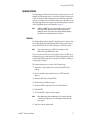
Updating Software . . . . . . . . . . . . . . . . . . . . . . . . . . . . . . . . . . . . . . . . . . . . . . . . . .
Overview . . . . . . . . . . . . . . . . . . . . . . . . . . . . . . . . . . . . . . . . . . . . . . . . . . . . . . . .
Software Update Procedure. . . . . . . . . . . . . . . . . . . . . . . . . . . . . . . . . . . . . . . . .
Specifications. . . . . . . . . . . . . . . . . . . . . . . . . . . . . . . . . . . . . . . . . . . . . . . . . . . . . . . . .
Service . . . . . . . . . . . . . . . . . . . . . . . . . . . . . . . . . . . . . . . . . . . . . . . . . . . . . . . . . . . . . .
Troubleshooting GUI Operation . . . . . . . . . . . . . . . . . . . . . . . . . . . . . . . . . . . . . .
Functional Description . . . . . . . . . . . . . . . . . . . . . . . . . . . . . . . . . . . . . . . . . . . . . . . .
Temperature Sensing . . . . . . . . . . . . . . . . . . . . . . . . . . . . . . . . . . . . . . . . . . . . . . . .
ROM and RAM . . . . . . . . . . . . . . . . . . . . . . . . . . . . . . . . . . . . . . . . . . . . . . . . . . . . .
Ethernet Port . . . . . . . . . . . . . . . . . . . . . . . . . . . . . . . . . . . . . . . . . . . . . . . . . . . . . . .
RS-232 Serial Port . . . . . . . . . . . . . . . . . . . . . . . . . . . . . . . . . . . . . . . . . . . . . . . . . . .
Module Health Bus. . . . . . . . . . . . . . . . . . . . . . . . . . . . . . . . . . . . . . . . . . . . . . . . . .
Frame Bus. . . . . . . . . . . . . . . . . . . . . . . . . . . . . . . . . . . . . . . . . . . . . . . . . . . . . . . . . .
Module Present Detection . . . . . . . . . . . . . . . . . . . . . . . . . . . . . . . . . . . . . . . . . . . .
Fan Speed Control and Monitor . . . . . . . . . . . . . . . . . . . . . . . . . . . . . . . . . . . . . . .
On-board Regulator . . . . . . . . . . . . . . . . . . . . . . . . . . . . . . . . . . . . . . . . . . . . . . . . .
37
37
38
53
54
54
62
62
63
63
63
63
63
63
64
64
Appendix . . . . . . . . . . . . . . . . . . . . . . . . . . . . . . . . . . . . . . . . . . . . . . . . . . . . . . . . . . . . . . . . .
Compatibility Matrix . . . . . . . . . . . . . . . . . . . . . . . . . . . . . . . . . . . . . . . . . . . . . . . . . .
Control and Monitoring Support . . . . . . . . . . . . . . . . . . . . . . . . . . . . . . . . . . . . . .
Control and Monitoring Notes . . . . . . . . . . . . . . . . . . . . . . . . . . . . . . . . . . . . . . . .
8900–FLOAD–CBL Assembly . . . . . . . . . . . . . . . . . . . . . . . . . . . . . . . . . . . . . . . . .
65
65
67
67
67
Index . . . . . . . . . . . . . . . . . . . . . . . . . . . . . . . . . . . . . . . . . . . . . . . . . . . . . . . . . . . . . . . . . . . . . .
69
8900NET Instruction Manual
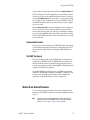
Preface
About This Manual
This manual describes the features of a specific 8900 module in the Gecko
Signal Processing System family. As part of this module family, it is subject
to Safety and Regulatory Compliance described in the Gecko 8900 Series
frame and power supply documentation (see the Gecko 8900 Frames Instruction Manual).
8900NET Instruction Manual
5
Preface
6
8900NET Instruction Manual
8900NET Network Interface
Module
Introduction
The 8900 Network Interface module (8900NET) is designed to operate in all
Gecko 8900 Signal Processing frame versions.
Note
The 8900TX-V/-A frame must be upgraded to a TF-V/-A frame (with fans)
before installing an 8900NET module.
The 8900NET module provides control and monitor access to the frame and
its audio/video modules through a web browser graphical user interface
(GUI). The 8900NET enables remote configuration and monitoring of the
enhanced Gecko 8900 frame and its remote control capable modules.
8900NET Features
The 8900NET module features:
•
10 Base-T Ethernet interface,
•
HTML protocol support,
•
Fan front cover power and control,
•
Frame health monitoring,
•
Software update downloading support,
•
Support for the Newton Modular Control system control panels,
•
Support for Frame Alarm,
•
Support for Simple Network Management Protocol (SNMP) monitoring, and
•
Support for NetConfig application.
8900NET Instruction Manual
7
Introduction
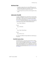
Remote Control Panel
The 8900NET module with version 2.1 or later software allows the frame to
be remotely controlled by external control panels. These panels are connected via the Ethernet port. Refer to the control panel documentation for
details.
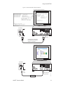
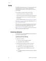
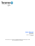
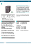
Basic Network Design
The 8900NET module can be employed in either a point-to-point or local
area network (LAN) control/monitoring configuration. Figure 1 illustrates
a point-to-point configuration.
Figure 1. Point-to-point Configuration
Ethernet cable, Category 5 Crossover
LOCK
LOCK
FAULT
PS 1
PS 2
0612-08
PC running:
Windows 95/98/NT,
Unix, or Macintosh OS
Ethernet
Netscape Navigator 4.x
or Internet Explorer 4.x
8900TFN frame with
Network Interface Module
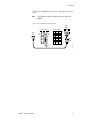
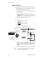
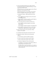
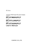
Figure 2 illustrates a typical LAN configuration.
Figure 2. Basic Network Configuration
LOCK
LOCK
FAULT
PS 1
PS 2
8900TFN frame with
Network Interface Module
Ethernet cable: Category 5
PC running:
Windows 95/98/NT, Unix
or Macintosh OS
Ethernet
Netscape Navigator 4.x
or Internet Explorer 4.x
LAN Ethernet Hub
LOCK
LOCK
FAULT
PS 1
PS 2
8
0612-07
8900TFN frame with
Network Interface Module
8900NET Instruction Manual
Installation
Installation
This section describes placing the module in the Gecko 8900 frame and
cabling the communications ports. Procedures for power-up, DIP switch
settings, and network configuration of the module are described in following sections.
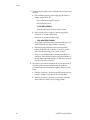
Module Placement in the Gecko 8900 Frame
There are ten cell locations in the frame to accommodate either analog or
digital modules. These are the left ten locations. Refer to Figure 3.
The two cells on the right are allocated for the power supplies. For additional information concerning the Power Supply module, refer to the 8900
Series Frames Instruction Manual.
The third cell from the right is allocated for the 8900NET Network Interface
or Frame Monitor module. For additional information concerning the
Frame Monitor module, refer to the Gecko 8900 Series Frames Instruction
Manual.
Figure 3. 8900 Series Frame
0612-04r1
Any 8900 Module
Power
Supplies
(only)
Frame Monitor
or 8900NET Network
Interface Module (only)
Note
8900NET Instruction Manual
The 8900NET module can be plugged in and removed from a Gecko 8900
Series frame with power on. When power is applied to the module, LED indicators reflect the initialization process (see Power Up on page 16).
9
Installation
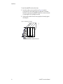
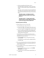
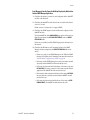
To install the 8900NET module in the frame:
1. Insert the module, connector end first (see Figure 4), with the
component side of the module facing to the right side of the frame.
Instead of an ejector tab, the 8900NET module has a connector tab with
a circular finger-hole for pulling the module.
2. Verify that the module connector seats properly and securely against
the backplane.
Figure 4. Module/Frame Orientation
0612 -16
S1
1 2 3 4 5 6 7 8
1 2 3 4 5 6 7 8
Component side
Configuration DIP switches
10
8900NET Instruction Manual
Installation
Cabling
This section describes physical connections, the connectors and cables,
used for network communications. Setup procedures for each type of connection are described in Establishing Frame Network Identity on page 19.
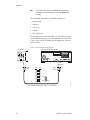
An example of control and monitoring connectors on the 8900TFN frame
are illustrated in Figure 5.
Note
There are several versions of frames in the Gecko 8900 Series. Refer to the
8900 Series Frames manual that came with your frame for the latest information on cabling.
Figure 5. 8900NET Input/Output Connectors on 8900TFN Frame
RS232
J1
J2
Frame Alarm
(Video – J102 pins 8 and 9)
(Audio – J7 pins 8 and 9)
Network configuration storage
Frame ID
(Frame MAC address storage)
ETHERNET
0612_31
Frame Alarm
The Frame Alarm is accessed through pins 8 and 9 of the RS-232 connector.
Details for connecting an external customer-supplied alarm are given in the
Gecko 8900 Series Frames Instruction Manual.
Note
Earlier version 8900 frames used a BNC connector labelled SMPTE ALARM
to access the alarm connection. For information concerning the SMPTE
Alarm bus cable, refer to the Gecko 8900 Frames Instruction Manual.
RS-232 Communication Port Cable
The nine-pin RS-232 connector is used to connect the frame to a PC to initially set the frame’s network communication parameters. After network
communication is established, subsequent changes to these parameters can
be made using the network GUI.
CAUTION The RS-232 cable should be removed after completing the initial frame setup.
Leaving a long serial cable connected to the frame without a connection at
the other end may freeze the 8900NET module startup routine.
8900NET Instruction Manual
11
Installation
Note
The cable used for this connection is a DB-9F to DB-9M, straight-through
cable available from Grass Valley as part of cable kit model 8900CAB (10 ft./
3 m length).
The communication parameters for the RS-232 connection are:
•
Baud rate: 9600
•
Data bits: 8
•
Parity: none
•
Stop bits: 1
•
Flow control: none
The male end connects to J102–Video/BNC or J7–Audio RS-232 connector
on the 8900 TFN frame (see Figure 6) and the female end connects to either
Com1 or Com2 on the PC, depending upon the configuration of the computer’s I/O ports.
Figure 6. RS-232 to Initialization PC Cable and Pinout
PC running Hyperterm Terminal Emulation
8900TFN Frame
RS-232
Com1 or
Com2 port
DB-9
Male
Pin
1
2
3
4
5
6
7
8
9
DB-9
Female
Pin 1
Pin 5
Pin 9
Comm. Parameters: 9600 baud, 8 bits, parity-none, 1 stop, flow-none
12
0612 -09r1
1
2
3
4
5
6
7
8
9
Pin
8900NET Instruction Manual
Installation
If the PC uses a 25-pin RS-232 connector, use a cable adapter as shown in
Figure 7.
Note
The 25-pin adaptor is available from Grass Valley as part of cable kit model
8900CAB.
Figure 7. DB-9 Cable and DB-25 Cable Adaptor Pinout
DB-25
Female
9-pin 9-pin
DB-9
Male
1
2 Tx
3 Rx
4
5
6
7
8
9
20
22
9-pin 9-pin 25-pin
1
1
8
2
2
3
3
3
2
4
4
20
5
5
7
6
6
6
7
7
4
8
8
5
9
9
22
DB-9
Female
0612 -11
8900NET Instruction Manual
1
Tx 2
Rx 3
4
5
6
7
8
9
25-pin
13
Installation
Ethernet Cable
The 8900NET module enables the frame’s RJ-45 Ethernet connector.
Through this port the 8900 frame can connect to:
•
A single PC with a network card (point-to-point), or
•
A local area network (LAN) through a network hub.
Point-to-Point Connection
Figure 8 illustrates the crossover cable connection and pinout for a pointto-point connection to the controlling PC.
Note
This Category 5, UTP Crossover Cable is available from Grass Valley as part
of cable kit model 8900CAB (10 ft./3 m length).
Figure 8. Point-to-Point RJ-45 Connection and Cable Pinout
PC with network card and net browser software
8900TFN Frame
Ethernet
RJ-45
connector
To PC network card
RJ-45 connector
Pin
1
2
3
4
5
6
7
8
Pin
1
2
3
4
5
6
7
8
Pin
1
2
3
4
5
6
7
8
Pin
3
6
1
5
4
2
8
7
14
RJ-45
connector
0612 -10r1
Category 5, UTP Crossover Cable
Pin 1
8900NET Instruction Manual
Installation
Local Area Network (LAN) Connection
Figure 9 illustrates the cable connection for a LAN connection to a network
hub.
Note
Because of varying length requirements and ready availability from network
equipment suppliers, this cable is not supplied by Grass Valley.
Figure 9. LAN RJ-45 Connection and Cable
8900TFN Frame
Network Ethernet Hub (typical)
8 7 6 5
hp
4 3 2 1
10 BaseT
Ethernet
To network hub
RJ-45 connector
RJ-45
connector
Pin
1
2
3
4
5
6
7
8
Pin
1
2
3
4
5
6
7
8
Pin
1
2
3
4
5
6
7
8
Pin
1
2
3
4
5
6
7
8
8900NET Instruction Manual
RJ-45
connector
0612 -15r1
Category 5, UTP Cable
Pin 1
15
Power Up
Power Up
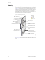
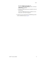
The various front LED indicators and configuration switches are illustrated
in Figure 10. Upon power-up, all LEDs should light for the duration of the
initialization process. After initialization the Power LED will be on and the
red Network Module LED (labeled NM) should go off. All other LEDs
report detected conditions within the frame and the installed modules. If
the NM LED does not go off, the board needs servicing.
Figure 10. LEDs and Configuration Switches
LED Color Key
Red = Fault
Green = OK
Yellow = Active
TEMP - Temperature (red)
PS2- Power Supply 2 (red)
PS1 - Power Supply 1 (red)
FAN (red)
PWR - Power (green)
MOD - Module Health Bus (red)
FB - Frame Bus (red)
INHIB - Module Health Inhibited
(yellow)
NM - Network Interface Module (red)
S1
COMM - Communication (yellow)
ETHER - Ethernet communiction
(yellow)
1 2 3 4 5 6 7 8
FAULT - Frame Fault (red)
Configuration DIP switch S1
Configuration DIP switch S2
(functions currently not supported)
1 2 3 4 5 6 7 8
0612 -06
REM OVR - Remote Override
(yellow)
Table 1 on page 17 describes all the module’s LEDs and the conditions indicated.
16
8900NET Instruction Manual
Power Up
Monitor Module Indicator LEDs
The possible LED status and conditions indicated are shown in Table 1.
Table 1. Indicator LEDs and Conditions Indicated
LED
LED State
POWER
(green)
On continuously
Off
Off
TEMP
(red)
On continuously
PS2
(red)
On continuously
Off
Off
PS1
(red)
On continuously
Off
FAN
(red)
On continuously
Off
MOD
(red)
On continuously
Long continuous flashing
Condition
Power is off or on-board regulator has failed
Module is powered
Frame temperature is within specified parameters
Over-temperature condition detected in frame
Normal operation or alarm disabled
Power supply 2 is present and reporting an alarm condition
Normal operation or alarm disabled
Power supply 1 is present and reporting an alarm condition
Normal operation or alarm disabled
One or more fans in the front cover assembly is not rotating
Normal operation or alarm disabled
Module health bus is not disabled and one or more modules is reporting an internal
fault
One or more modules is reporting a configuration error
FB
(red)
Off
Network module is communicating with modules on the frame bus
On
Internal frame bus communication failure
INHIB
(yellow)
Off
Normal operation or alarm disabled
On continuously
Off
FAULT
(red)
On continuously
Flashing
A non-compliant module in the frame has disabled the module health bus
Normal operation
One of the on-board fault LEDs is illuminated or flashing
Indicates the MOD (module health LED) is flashing
COMM
(yellow)
On
Indicates module is polling the devices on the internal frame communication bus
ETHER
(yellow)
On
Indicates active communication detected on the Ethernet bus
Off
All fault reporting is controlled by onboard configuration switches
On
Software overrides onboard configuration switches
REM OVR
(yellow)
8900NET Instruction Manual
17
Enabling Alarms and Fan Speed Control Option
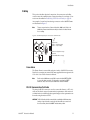
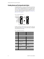
Enabling Alarms and Fan Speed Control Option
The 8900NET module has two eight-position DIP switches (S1 and S2) that
enable or disable the fault reporting functions and the variable fan speed
option (see Figure 11). Enabled fault alarms drive on-board LEDs and can
also be sent to SNMP monitoring stations when the SNMP network and
Agent software has been installed and configured (see Network Module Configuration for SNMP on page 30).
Figure 11. Alarm Reporting DIP switches
S1
Status
IP Address
Frame Control
Remote
Override
LED
1 2 3 4 5 6 7 8
1 2 3 4 5 6 7 8
Power Supply #1
Power Supply #2
Temperature
Fan
Module
Frame Bus
Fan Speed
NM Control
S2
8900NET
Disabling (or filtering) specific fault alarms can be useful in isolating problems in the frame. Refer to Table 2 for the possible settings. A settings table
is also silk-screened on the module.
Table 2. Configuration DIP Switch Settings
S1 Segment
Right Position (closed)
PS1 Fault Reporting Enabled
PS1 Fault Reporting Disabled
2
PS2 Fault Reporting Enabled
PS2 Fault Reporting Disabled
3
(Not used) Over Temp reporting is always enabled locally and through SNMP
4
Fan Fault Reporting Enabled
Fan Fault Reporting Disabled
5
Module Fault Reporting Enabled
Module Fault Reporting Disabled
6
Frame Bus Error Reporting Enabled
Frame Bus Error Reporting Disabled
7
Fan Speed Controlled by Temperature
Fan Speed Fixed at Maximum
8
Network Module Control Enabled (remote
control via GUI is enabled)
Network Module GUI is placed in read only
mode
S2 Segment
Left Position (open)
1
Status Enabled (enabled alarms are
reported over SNMP)
2
IP Address (not currently supported)
3
Frame Control Enabled (remote control via
GUI is enabled)
4–8
18
Left Position (open)
1
Right Position (closed)
SNMP Reporting is disabled except for
Over Temp alarm
GUI for the frame and all modules within is
placed in read only mode
(Currently Not Used)
8900NET Instruction Manual
Establishing Frame Network Identity
Establishing Frame Network Identity
The initial configuration of the 8900NET module, using the RS-232 port
(refer to Figure 6 on page 12), establishes the frame’s network identity to
enable the operation of the Web-based GUI. A PC running a terminal emulation application is used to set the initial parameters for network communication. Once initial identity is established, the GUI can be used to make
subsequent changes to the networking parameters. Parameters established
include:
•
Local IP Address,
•
Gateway IP Address,
•
Subnet Mask, and
•
Default Route.
Note
If the Gecko 8900 frame is to be connected point-to-point to a single PC
workstation, both the frame and the PC must be on the same Subnet.
NetConfig Application
With this software release, Gecko 8900 Series frames can interface with NetConfig (Network Configuration Application). NetConfig is a PC software
tool for configuring and setting up NetConfig-enabled Grass Valley
devices. Refer to the NetConfig Manual or the 8900NET Release Notes for
current information on using this tool.
Good Networking Practices
The Local IP Address form of a URL can be used within an intranet to
address the Gecko 8900 frame’s web page. An intranet is set up and maintained within your facility and is isolated from the Internet.
Access from outside, through the Internet, may require the use of a Domain
Name and a firewall, depending upon your network architecture. Domain
Name Addressing requires a Domain Name Server located within the
intranet that maps the Domain Name to the frame’s IP Address. The
8900TFN frame has no knowledge of its assigned Domain Name. Network
traffic through a Domain Name Server can delay 8900NET response time.
Remote workstations are also subject to network traffic delays. Local PC
workstations should be used for real-time operation of the 8900NET.
The most direct and timely access to the frame is achieved by using a PC
workstation that is assigned to the same Subnet (see Figure 12). A workstation in a different Subnet, even when located on the same router, will be
subject to processing of the IP Gateway.
8900NET Instruction Manual
19
Establishing Frame Network Identity
Figure 12. Local IP and Subnet Addressing
Subnet 2
IP Gateway
Remote PC
182.1.2.2
Subnet 1
182.1.2.1
LOCK
LOCK
FAULT
PS 1
PS 2
127.1.2.1
8900TFN frame 127.1.2.3
Router
LOCK
LOCK
FAULT
PS 1
PS 2
8900TFN frame 127.1.2.4
FTP Server
127.1.2.6
0612-17
Local PC
127.1.2.5
Setting Frame Network Identity
After you have connected the PC to the RS-232 port (refer to RS-232 Communication Port Cable on page 11) and established communication using the
terminal emulation application, press the enter/return key several times to
see the active prompt.
At the prompt enter:
setup
You will see:
-> setup
Here are the current parameters and their values:
Local IP Address:
Gateway IP Address:
Subnet Mask:
20
192.158.211.83
192.158.211.1
255.255.255.0
8900NET Instruction Manual
Establishing Frame Network Identity
If a change is made, it is necessary to reboot
this machine. This will occur automatically when
you have completed making changes.
Do you wish to change any of the values? y/n (n): y
For each parameter, you will be given the name of the
parameter and its current value in parenthesis. To
change it, just type in the new value. If you don't
wish to change it, just hit the Enter key.
If you make a mistake on a previous value, continue
with the remaining parameters; you will be given an
opportunity to modify the value again.
Please ensure that you change from Factory defaults
to your network parameters.
The local Ip Address is the Internet address of this
machine. It consists of four numbers separated by periods ('.'). Each number can be in the range of 0 to
255. For example: 192.167.221.45
There must an IP address.
IP Address (192.158.211.83):
The Default Route is the Internet address of the machine which routes network packets outside of the local network. It consists of four numbers separated by
periods ('.').
Each number can be in the range of 0 to 255.
For example: 192.167.221.1
If you respond with a single period (.),a default
route will not be assigned.
Default Route (192.158.211.1):
The Subnet Mask is used in the routing algorithm.
The Net Card will use the mask to determine if a address is in local net or to send the message to the
default. It consists of four numbers separated by periods ('.').
Each number can be in the range of 0 to 255.
For example: 192.167.221.1
If you respond with a single period (.),
a Subnet Mask will not be assigned.
Subnet Mask (255.255.255.0):
8900NET Instruction Manual
21
Web Browser Setup
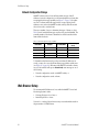
Network Configuration Storage
8900NET software version 3.0.0 and later enables storage of the IP
addresses (network configuration) on the frame backplane on frames that
are equipped with storage capability (see Figure 5 on page 11). In earlier
versions of software and frame types with no storage capacity, the IP
addresses are stored on the 8900NET module and stay with the module
when it is moved to another frame.
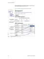
There are a number of ways to determine what type of frame you have.
Table 3 lists all available frame types and how they can be identified. The
assembly number of the frame is identified on a label located inside the
frame inside the chassis.
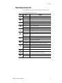
Table 3. 8900 Frames Types IP Storage Capability
Model Number
Backplane
Assembly Number
Network Config
Storage
8900TFN-A
Audio backplane with 1 IC
610-0960-00
8900NET module
8900TFN
Video backplane with 1 IC
630-0063-00
8900NET module
8900TFN-A
Audio backplane with 2 ICs
610-0960-01
Frame backplane
8900TFN-V
Video backplane with 2 ICs
610-0984-00
Frame backplane
To determine what frame model you have and where IP addresses are
stored, you may also access the Frame Status page with the web browser
(see Figure 16 on page 29). All frames with 8900NET cards with software
version 3.0.0 and later will report a Network Config status message as one of
the following:
•
Network configuration stored on 8900NET module, or
•
Network configuration stored on frame.
Web Browser Setup
The recommended Web browser for use with the 8900NET Control and
Monitoring System is either:
•
Netscape Navigator 4.x or later, or
•
Internet Explorer 4.x or later.
Versions 3.x or earlier of these browsers may cause undesirable results in
the presentation of HTML frames.
22
8900NET Instruction Manual
Web Browser Setup
Web Browser Notes
•
If applicable, configure the browser for direct HTTP requests to the
frame rather than addressing a Proxy Web Server. The Modular Frame
Web Server will typically be installed inside the firewall.
•
For older Netscape browsers, the Cache should be configured to always
refresh.
Addressing the Frame URL
To address an 8900TFN frame from an internet browser, enter the frame’s
default URL into the URL line of the browser (“Location” in Netscape Navigator, “Address” in Internet Explorer). The URL will be the IP Address
given to the frame during initial setup (see Setting Frame Network Identity
on page 20), or a Domain name that has been mapped to the IP Address in
your Domain Name Server tables. The URL should look like this:
http://{Frame’s IP Address}/
Example:
http://127.123.234.2/
Or:
http://{Frame’s Domain Name}/
Example:
http://frame1.xyz.com/
The correctly entered URL will call up the 8900 frame’s default first page—
Frame Status.
Default MAC (machine) Address
Each 8900TFN frame has a unique ethernet physical level MAC address
that is stored in the frame ID memory chip (see Figure 5 on page 11). If this
memory is missing, the 8900NET module will substitute a default MAC
address: 08-00-11-09-CD-AB. If more than one 8900 frame in your network
is assigned the default MAC address, network conflicts will occur. To verify
the frame has a unique MAC address refer to Module ID and Network Parameters on page 35.
8900NET Instruction Manual
23
Using the 8900NET GUI
Using the 8900NET GUI
Once the frame’s first page—Frame Status—has been accessed (see
Figure 13 on page 25), navigation can be done using the hypertext Link List
in the left column.
The Link List is a two-tier list with the frame’s devices at the highest tier
and sub-pages for each device in a secondary tier (sub-list) below the
parent device.
To navigate from device to device, click on a device link. This will open the
device’s status page and open the sub-list of device pages. You can also
click on the slot icon in the content display to access a particular module’s
status page.
To navigate to one of the device’s pages click on any of the device’s sub-list
of links. This will update the content display to the right.
Note
To update status, html pages must be manually refreshed by clicking on the
Refresh button (to the right of the page title). Changes made at the frame or
from other browsers on the network will not be displayed until the page is
refreshed.
8900 Frame Interface
This section describes GUI functions for the 8900 frame.
Frame Status Page
The Frame Status Page (Figure 13 on page 25) displays an overall status for
the frame.
The top section reports the following for the frame:
•
Model Number,
•
Description,
•
Frame Location (set in Frame Configuration),
•
Temperature Status,
•
Warning messages, and
•
Front Cover status (Cover installed, No Cover)
The graphical content display shows:
24
•
Module slot status,
•
Power supplies installed (and empty slots),
•
Presence of the 8900NET module (Net Card), and
•
A clickable link to each device’s status page.
8900NET Instruction Manual
Using the 8900NET GUI
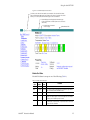
Figure 13. 8900NET GUI for Frame Control
The Links section lists the frame and its current modules. The selected link's Status
page is first displayed and the sub-list of links for the selection is opened. The sub-list
allows you to select a particular information page for the selected device.
Content display section displays the information page
for the selected frame or module (frame slot icons are also
active links).
Refresh button for manual
refresh of page
Online Manual Link
0612-12r1
Module Slot Status
Module Slot Status icons report one of the following (Table 4):
Table 4. Module Status Indicators
Icon
Color
Module
Status
Icon
Text
White
None
Gray
No Comm No Comm Slot contains a legacy module which was not designed to support Frame
Bus communications with an 8900NET module.
Green
Pass
Module
Slot contains a fully Frame Bus capable module.
Yellow
Warning
Module
8900NET has detected a warning condition in module due to lack of input
signal or incomplete support for remote monitoring and control. Ability of
module to perform intended operation is limited.
Red
Fault
Module
8900NET has detected a fault condition in module. Fault may have been
communicated over the Frame Bus, or may indicate a failure of the module
to respond over the Frame Bus.
8900NET Instruction Manual
Empty
Indication
No module detected in slot.
25
Using the 8900NET GUI
During initial polling, modules that do not respond immediately may transition to a WARNING, MODULE NOT RESPONDING status. In this case, this is a temporary status until a maximum number of sequential attempts fail and a
Fault is reported.
Note
The first release of 8960DEC module code causes a Fault condition because
it never responds on the Frame Bus. There is no way for the 8900NET module
to tell the difference between a fully functional early release of 8900DEC and
a module whose Frame Bus Interface has failed.
Note
Early releases of the 8960ENC, 8950DAC, 8950ADC, 8920DAC, 8920ADC,
and the 8916 signal a warning condition due to limited capability over the
Frame Bus. All of these, except the 8916, can be upgraded by the user with
fully capable Frame Bus software.
Frame Properties
The Properties section on the Frame Status page reports:
•
Vendor name,
•
Number of media module slots,
•
Software version (installed on the 8900NET module),
•
Network Config (whether the network configuration is stored on the
8900NET module or on the frame backplane, depending on frame
model). Refer to Network Configuration Storage on page 22.
Older and Legacy Module Support
8900 and legacy Grass Valley modules that can reside in the 8900TFN frame
are supported to different degrees by the 8900NET module. A compatibility matrix describing the hardware versions, software update methods
requiredm, and remote control features of the various modules supported
by the 8900 frames and 8900NET module is located in the Compatibility
Matrix on page 65.
Note
26
When the 8900NET is first installed or when many modules are installed
simultaneously, it may take some time for the 8900NET to poll, update status
and build the HTML pages, especially if there are modules that do not
respond as expected, such as legacy modules. During these periods the
Frame Status Page may fall behind temporarily until the 8900NET board can
catch up and present a true current status.
8900NET Instruction Manual
Using the 8900NET GUI
Legacy Module Support
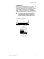
Installation of 8500 and 8800 modules shipped prior to November 15, 1999
will cause interruption of the 8900TFN frame communication bus.
Modules shipped after this date have pins removed in the rear connector to
provide compatibility. Compatible modules can be identified by the
absence of connector pins 10 and 50 (see Figure 14). Incompatible legacy
modules can be returned to Grass Valley for upgrade to the new connector.
Note
If an unmodified legacy module is installed in the frame, the frame communication bus will be interrupted and all module icons in the frame status
display will be red. This problem occurs with legacy modules only and does
not occur with Gecko 8900 Series modules.
Figure 14. Modified Legacy Module Connector
Top of Module
Pin 2
Pin 10
Pin 50
Typical
8900NET Instruction Manual
0612-18
Pin 50
Removed
27
Using the 8900NET GUI
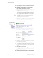
Frame Configuration Page
Use the Frame Configuration page shown in Figure 15 to:
•
Activate the Locate Frame function,
•
Save or recall a frame configuration to a default file,
•
Assign the frame a name, index number, and location,
•
Designate a Documentation Server Address for accessing user manuals
in pdf format, and
•
Enabling/disabling frame status reports for SNMP monitoring.
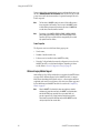
Figure 15. 8900 Frame Configuration Information
Select Configuration
To physically locate a frame,
select and apply Flash to flash
the frame's front cover LEDs
Save the current frame
and slot configuration
to a file
Enter a path and filename to recall
a saved frame configuration file
Load the selected
configuration file
Name the frame and its location.
Enter an index number to be used
in SNMP networking tables
(not required)
Enter IP Address for
online manual server
Enable or disable the various
status reports used in SNMP
network monitoring system
Note: To enable a report,
on-board switches
must also be enabled
28
8900NET Instruction Manual
Using the 8900NET GUI
8900NET Module Interface
This section describes GUI functions for the 8900NET module.
Viewing Network Module Status
The Status page illustrated in Figure 16 displays 8900NET:
•
Module identity, location and internal diagnostic Pass/Fail /Warning,
status,
•
Hardware and software properties, and
•
Status of on-board hardware configuration switches (set as described in
Enabling Alarms and Fan Speed Control Option on page 18).
A Status LED icon on each module page changes color to report status of
network interface, frame bus, and internal diagnostics:
•
Green indicates a Pass condition,
•
Red indicates a Fail condition, and
•
Yellow indicates a Warning condition.
Figure 16. 8900NET Module Network Status Page
Select Status
Status icons
Hardware and
software information
On-board configuration
switch settings
8900NET Instruction Manual
29
Using the 8900NET GUI
Network Module Configuration for SNMP
The Grass Valley Modular Control and Monitoring System uses the Simple
Network Monitoring Protocol (SNMP) internet standard for reporting
status information to remote monitoring stations. The 8900NET Configuration page provides SNMP setup. When SNMP Agent software is installed
on the 8900NET module, enabled status reports are sent to an SNMP
Manager such as the Grass Valley’s NetCentral application.
Note
There are both hardware and software report enable switches for each report.
Both must be enabled for the report to be sent. Software report switches are
set on the 8900NET Configuration page for the Frame, the 8900NET module,
and each module slot.
SNMP Agent Installation
To use SNMP, the SNMP Agent software must be installed on the module.
The Configuration page shown in Figure 17 is displayed if the agent software has not already been installed. Click on the install button to view the
license agreement.
Figure 17. Configuring the 8900 Network Module for SNMP
Select Configuration
30
8900NET Instruction Manual
Using the 8900NET GUI
After reading the agreement, click on Agree to finish installing the SNMP
Agent (Figure 18). Clicking the Decline button will abort the SNMP Agent
installation and return you to the Configuration page.
Figure 18. Installing the SNMP Agent
8900NET Instruction Manual
31
Using the 8900NET GUI
When the SNMP Agent is successfully installed, the Configuration page
will contain the setup items shown in Figure 19.
Figure 19. Configuring the 8900 Network Module with SNMP Agent Installed
Select Configuration
Enable/disable SNMP
status reporting
Enable/disable SNMP
level of report severity
Enter a destination
IP address and
Community Name for
up to five monitoring
SNMP stations
Activation control
Activation status
32
8900NET Instruction Manual
Using the 8900NET GUI
SNMP Report Activation
Each report destination has an activation control that can select one of the
following modes of operation:
•
CREATE – GO creates a new report destination that becomes active after
the next module reboot.
•
CREATE – WAIT creates a new report destination that remains out of
service until the user selects active and then reboots the module.
•
ACTIVE changes a NOT IN SERVICE report destination to active after the next
module reboot.
•
NOT IN SERVICE changes an active report destination to inactive after the
next module reboot.
•
DELETE removes the report destination entry. If the entry was active it
remains active until the next module reboot.
Note
Report destination status does not change until the 8900NET module is
rebooted.
The status column to the left of the activation operation pull-down window
provides one of the following status reports:
•
<BLANK> – No entry has been applied.
•
ACTIVE – All new status reports will be sent to this destination.
•
NOT IN SERVICE – The destination has a valid definition but the user has
not activated it.
•
ACTIVE PENDING REBOOT – This entry indicates the report destination will
become active upon the next module reboot.
•
NOT IN SERVICE PENDING REBOOT – This entry indicates the report destina-
tion will become inactive upon the next module reboot.
•
NOT READY – The destination entry is invalid. The IP Address may not be
properly defined or there is no IP Address or Community entry.
8900NET Instruction Manual
33
Using the 8900NET GUI
Media Module Slot Configuration
Media module slots may be named to reflect specific functions for that slot
or module within the facility. The assigned name is stored on the 8900NET
module and travels with that module if it is moved to another frame. To
assign a slot name you must access the specific slot’s page and open the Slot
Config menu for that slot. An example for the 8960DMX is shown in
Figure 20.
Figure 20. Media Module Slot Configuration Page
Select Slot Config
Enable/disable module
locator function
Name the module slot
Identify the input signal
Check box to restore
saved config when
new module installed
Learn module configuration
to this slot
Read-only status of 2000NET
module hardware settings
necessary for enabling
SNMP Trap Reports
Enable/disable specific
SNMP reports for the slot
Read-only severity level
assigned to each event
Locate Module
When enabled, the Locate Module function flashes the yellow COMM and
CONF LEDs on the front of the module to locate in the frame.
Slot Identification
You may identify the module by typing a specific name in the Name field.
The assigned name is stored on the 8900NET module and travels with the
8900NET module if it is moved to another frame. Select Default to enter the
factory default module name.
34
8900NET Instruction Manual
Using the 8900NET GUI
Assign a name to the input signal to the module in the Input Signal Name field.
The slot configuration for each media module is automatically saved periodically (once an hour) to the 8900NET module in that frame. You may also
select the Learn Module Config button at any time to save the current configuration for this slot. The configuration is saved on the 8900NET module. If
the 8900NET module is removed or powered down, the stored configurations are not saved.
When the Restore upon Install box has been checked, the current configuration
saved to this slot is saved as slot memory. When the current module is
removed and another module of the same type is installed, the configuration saved to the 8900NET module will be downloaded to the new module.
The box must be checked before the current module with the saved configuration is removed.
Hardware Switch Controls
This section is a read-only status report of 8900NET module switch settings
for Module Status Reporting and Asynchronous Status Reporting. These
functions must be enabled for the following Slot SNMP Trap Reports to
function.
Slot SNMP Trap Reports
This section is displayed only when the SNMP Agent software has been
installed on the 8900NET module. Slot SNMP traps can be enabled only
when the hardware switches for Module Fault reporting and Asynchronous Status reporting are in enabled on the 8900NET module (dipswitch S1
segment 7 and dipswitch S2 segment 1).
The enabled SNMP traps will be reported to any SNMP manager that is
identified as an SNMP Report Destination in 8900NET configuration. Trap
severity is read-only hard-coded information that is interpreted and
responded to by the SNMP Manager software configuration.
Module ID and Network Parameters
To view or change the module identity and currently assigned network
addresses for the 8900NET module access the Network page illustrated in
Figure 21.
Note
8900NET Instruction Manual
Depending on the type of frame this module is installed in, this network configuration is saved on either the 8900NET module or on the frame backplane.
Refer to Network Configuration Storage on page 22 for details.
35
Using the 8900NET GUI
Figure 21. 8900NET Module Network Identification Page
Select Network
Frame machine address
After initial frame network addressing is done using the RS-232 port, subsequent address changes may be made using the menu shown above.
Note
SubNet Mask and Gateway IP Address are required.
Rebooting the NET Module
You can reboot the 8900NET module from the Network page by clicking
the Reboot button. A Reboot button can also be found on the Configuration
page.
36
8900NET Instruction Manual
Using the 8900NET GUI
Updating Software
The following procedure describes the software download process for the
8900NET module running version 3.2.0 and later. Software download procedures for media modules residing in the networked Gecko 8900 frame
will vary according to release date and hardware version. Modules can use
the following procedure or may require a special cable assembly as detailed
in the Compatibility Matrix in the Appendix on page 65.
Note
Updating the 8900NET from version 2.1 and earlier to version 3.2.0 or later
must be done with an application available from Grass Valley. Software
updating after version 3.2.0 can also be done using the NetConfig application
if installed. Refer to the NetConfig manual for instructions.
Overview
The Modular Remote Monitoring and Control System is an extension of the
Grass Valley Signal Management System (SMS) routing system and uses
the same File Transfer Protocol (FTP) technique to download software.
Note
This procedure assumes your Local FTP Server computer is a 32-bit
Windows host running Win95, 98, NT or later.
If you do not have an FTP server, Grass Valley provides a free FTP server
package that is easy to install and operate. This procedure assumes you will
use the Xitami FTPD provided. If you already have an FTPD available, you
can skip steps 3 through 5.
The software update process consists of the following steps:
1. Acquire the software update files and, if needed, the FTP Server
package.
2. Place the module software update files into an FTPD modular
directory.
3. Extract the FTP Daemon (Xitami FTPD).
4. Run the Xitami installation program.
5. Modify the FTPD configuration files to the Xitami directory.
6. Start the FTPD.
7. Use the 8900 GUI to initiate software updates.
Note
When updating numerous Gecko 8900 modules, it is a good idea to dedicate
one frame for the update process to avoid interrupting communication with
active modules.
8. Verify the software update results.
8900NET Instruction Manual
37
Using the 8900NET GUI
Software Update Procedure
1. Acquire the software update files from Grass Valley (refer to Figure 22).
Software upgrade packages may be available on the Grass Valley web
site. The free FTP server software is also available.
a. Connect to the Grass Valley modular software upgrade site using
the following URL:
http://www.thomsongrassvalley.com/downloads/
Select Modular Products from the table. Files are located under 8900
Series Modules. Here you will also find the free FTP server software.
b. Create a temporary download directory on your PC:
c:\temp\
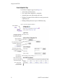
Figure 22. Acquiring 8900 Software from Grass Valley FTP Site
0612-24r1
Thomson Grass Valley Web Site
http://www.thomsongrassvalley.com
Typical Update Download
1. Module file (example): 8900net_sw2.exe
2. FTP Server file:
ftpd.exe
Internet
Resulting files
In a temporary directory: C:\temp\
Ethernet
1. Module file (example): 8900net.exe
2. FTP Server files:
xic3223c.exe
defaults.cfg
ftpusers.sms
readftpd.text
LOCK
LOCK
FAULT
PS 1
PS 2
8900TFN frame with
Network Interface Module
Extract to
C:\modular\8900
Move to
Xitami
Directory
Resulting files
Local
FTP Server
FTP Daemon Installed
Create a password protected
Modular directory
c:\modular\8900xxx
In Program directory:
C:\Program Files\Xitami
1. FTP Server file:
xic3223c.exe
defaults.cfg
ftpusers.sms
c. Using the web browser, select the desired files. Click to download
the file. You are queried to either OPEN the file or SAVE AS. Select the
SAVE AS option and set the path to the temporary directory on your
computer.
This process will trigger the download of the file to your computer.
Note
38
If you have access to an existing FTP Server’s directory, the module update
files can be downloaded directly into that directory.
8900NET Instruction Manual
Using the 8900NET GUI
2. Move or extract the module update files into an FTPD modular
directory.
The module software update files must reside in a directory that the
FTPD can access. The Grass Valley supplied FTPD is configured to
access a directory designated:
\modular\8900
The new software for the 8900 module will be either a binary file (.bin
extension) or a field update file (.fld extension). Binary files (.bin) are for
the 8900NET module updates and field update files(.fld) are for the
8900 Series modules.
a. Open Windows Explorer on the local server computer.
b. If one does not already exist, create a directory on the C drive:
c:\modular\8900
c. Double-click the module software.exe file (in the temporary
directory) and save it to the appropriate directory. The resulting file
will be a .bin or .fld:
c:\modular\8900\8900net_sw300a_fw1.fld
Note
The file name shown indicates: 8900NET, software version 3.00, firmware
version 1.0.
3. Extract the FTPD (Xitami FTP Server) files.
Note
This section is for facilities that do not already have an FTP Daemon (FTPD),
also known as a File Transfer Protocol (FTP) Server, installed on the Gecko
8900 frame’s network. For those facilities that already have an FTPD or other
FTP Service available in their network, go to step 6.
Grass Valley provides a free FTP server for those facilities that do not
have a local FTP service. The FTP server package is the same Xitami
Web Server-FTP package that is provided with the Grass Valley SMS
router upgrade package. The version of the Xitami Web-FTP server distributed with module software upgrades is for a 32-bit Windows host.
The FTP Daemon in the temporary directory is a self-extracting file
(ftpd.exe). To extract the files:
a. Open Windows Explorer and find the ftpd.exe file.
8900NET Instruction Manual
39
Using the 8900NET GUI
b. Double click on the .exe file and extract the files to the temporary
directory.
These files will be extracted:
•
xic3223c.exe – the Xitami installation file,
•
defaults.cfg – an FTPD configuration file that has been modified
specifically for Grass Valley software downloads, and
•
ftpusers.sms – the FTPD’s admin file specifying user names and
passwords network access to files in the ftp server directories.
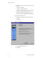
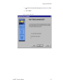
4. Run the Xitami installation program.
a. Double Click on xic3223c.exe. You will see the Xitami Welcome
(Figure 23).
b. Click on Next >.
Figure 23. Xitami Web Server Welcome
c. You will see Xitami Installation Notes.
d. Click on Next >.
40
8900NET Instruction Manual
Using the 8900NET GUI
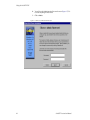
e. You will see Select Destination Directory (Figure 24). Do not change
the default settings.
f.
Click on Next >
Figure 24. Select Destination Directory
8900NET Instruction Manual
41
Using the 8900NET GUI
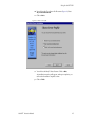
g. You will see the Select Program Group screen (Figure 25). Do not
change the default settings.
h. Click on Next >.
Figure 25. Select Program Group
42
8900NET Instruction Manual
Using the 8900NET GUI
i.
You will see the Automatic Startup Query screen (Figure 26). Select
No.
j.
Click on Next >.
Figure 26. Automatic Startup Query
8900NET Instruction Manual
43
Using the 8900NET GUI
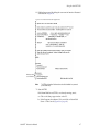
k. You will see the Administration Password screen (Figure 27). Do
not enter anything in these fields.
l.
Click on Next >.
Figure 27. FTPD Server Administration Password
44
8900NET Instruction Manual
Using the 8900NET GUI
m. You will see the Choose Server Profile screen (Figure 28). Select
Tiny - never block another task.
n. Click on Next >.
Figure 28. Choose Server Profile
o. You will see the Ready To Install screen. Click on Next >.
An installation meter box will appear, and upon completion, you
will see the Installation Complete! screen.
p. Click on Finish.
8900NET Instruction Manual
45
Using the 8900NET GUI
An Icon (see Figure 29) will have been created in the Program
Group window that was selected in Step g (see Figure 24 on
page 41).
Figure 29. FTPD Icon in Program Group Window
5. Move the FTP Daemon Start-up Configuration Files.
The FTP Daemon has now been installed and requires configuration files
be placed in the Xitami directory.
a. Open Windows Explorer.
b. From the Explorer window, return to the FTPD directory and move
the extracted defaults.cfg and ftpusers.sms files to the directory at:
c:\Program Files\Xitami
The defaults.cfg and the ftpusers.sms files contain default configuration instructions that the FTPD application reads at start-up.
46
8900NET Instruction Manual
Using the 8900NET GUI
6. Edit the ftpusers.sms file adding the user name information illustrated
at the bottom of Figure 30.
Figure 30. User Name and Password File ftpuser.sms
Modular product
user information
Note
The FTPD configuration files themselves should be installed in a password
protected directory.
7. Start the FTPD.
If the Xitami Web Server (FTPD) is not already running, start it.
a. Click on the Start popup window on the PC.
b. Select Programs, then Internet Tools, and click on Xitami Web
Server – 32 bit console (Figure 29 on page 46).
8900NET Instruction Manual
47
Using the 8900NET GUI
The Xitami Console will open as a DOS window. There will be a log
of events, at least one of which will indicate it is accepting connections (see Figure 31).
Figure 31. Typical FTPD Console Screen
Example. Actual
IP Address will be
the one assigned to
your FTP Server PC.
Ready message verifies
the FTPD is running.
The IP Address line should actually indicate the IP Address of the
PC you are using for the FTP server. This is the IP Address that will
be used to initiate the software update.
The line that verifies that the FTPD is running reads:
ready for FTP connections on port 21
8. With the FTPD running, use the 8900 GUI to initiate software updates.
Use the web-browser to:
•
Access the appropriate Software Update page for a given module,
•
Enter the required data into the HTML Form on that page, and
•
Submit the form.
The 8900 frame uses the data in the form to contact the FTPD on the
server, download the update file, and reprogram the targeted module.
48
Note
Prior to attempting update of software, refer to the target module’s manual
and confirm that the Remote/Local Only jumper is in the Remote position.
Note
To monitor the progress of the download, use the serial port connection (see
Figure 32) with a computer running a terminal emulation application
8900NET Instruction Manual
Using the 8900NET GUI
Figure 32. Serial Port Console and PC Network Connections
PC running Hyperterm Terminal Emulation
8900TFN Frame
Comm 1 or
Comm 2 port
RS-232
Serial Connection for console interface
Comm. Parameters: 9600 baud, 8 bits,
parity-none, 1 stop, flow-none
PC running web browser GUI
8900TFN Frame
Ethernet
RJ-45
connector
Ethernet Hub
8900NET Instruction Manual
0612 -29r1
To PC network card
RJ-45 connector
49
Using the 8900NET GUI
a. Open a web browser on a PC that is connected over the network to
the Gecko 8900 frame.
b. Enter the URL of the frame where the module to be updated
resides. The frame’s main status page will appear.
c. Click on the module’s link and then click on Software Update (the
8900NET module link is shown in Figure 33).
The module’s Software Update page will appear. This form is the
same for all 8900 modules that support network software update.
Note
Earlier 8900NET versions differ in the layout and number of entry fields. Nonessential fields have been removed in the later release.
If the module does not support network software update, the page
will be blank except for the header and status information.
Figure 33. 8900NET Module Software Update Page
Select Software Update
d. In the FTP Server Address field, enter the IP Address of the PC that
has the FTPD installed and running.
e. You can enter the Host Name of the PC that has the FTPD running
into the FTP Server Name field. This is an optional step and can be
omitted.
f.
Click on Apply to set the FTP Address.
The web page will refresh and the new FTP address should be displayed as the Current Settings.
g. In the File Path field, enter the file name of the software update file.
50
8900NET Instruction Manual
Using the 8900NET GUI
h. Submit the form and start the update process by entering the user
name and password and clicking on Apply.
After you click on Apply, the web page will display a Progress Monitor. Wait a few seconds for the Progress Monitor to begin.
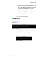
i.
If the file entered in the file path is invalid or the file cannot be
found, a File Not Found message will appear in the Progress Monitor
Results line (Figure 34). Select the Software Download link or the
Refresh button to refresh the page to return to the download page
and re-enter the file name.
Figure 34. 8900NET Software Download Progress Monitor
j.
If the login password is incorrect, the Progress Monitor will report
with a Login Incorrect message as shown in Figure 35. Select the
Software Download link or refresh the page to return to the
download page and re-enter the correct login.
Figure 35. Login Incorrect
8900NET Instruction Manual
51
Using the 8900NET GUI
k. Once the download has started and there are no error messages,
wait for the Success screen to appear, then click on Software Update
or the refresh button again to refresh the page.
Note
Do not click anywhere on the web page while the download is in progress
unless you receive a File Not Found or Login Incorrect Results message.
Once the download is successful, the Progress Monitor will report
a Success message similar to Figure 36.
Figure 36. 8900NET Software Update Failure Notice
9. Verify the software update results by checking the Installed Software
Version in Properties portion of the 8900NET Status web page.
The software and firmware (if applicable) numbers should match that
indicated in the .bin or .fld file name (see Step 2 of this procedure for file
names and version numbers).
Update Processing Details
Upon receipt of a software update form from a module, the 8900NET
module will contact the FTP Server, requesting the specified path. The
8900NET will send the user name and password to FTP server to gain
access to the file.
Once the file has been successfully FTP’d from the FTP Server, the 8900NET
will begin the module software compatibility check and upgrade process.
The module software compatibility check uses compatibility information
included in the Field Update File to ensure that the new software was
intended for this module. In the event that there is a mismatch, the
8900NET will abort the upgrade.
If compatibility is okay, the download is performed and the subject module
is rebooted.
52
8900NET Instruction Manual
Specifications
Specifications
Table 5. 8900NET Specifications
Parameter
Value
Recommended Software
Web browser
Netscape 4.x or Internet Explorer 4.x or later
PC operating system
Windows 95/98 or later
Terminal emulation
Hyperterminal
Environmental
Frame temperature range
0 to 45° C
Operating humidity range
0 to 90% non-condensing
Non-operating temperature
0 to 45° C
Mechanical
Frame type
8900 Series
RS-232 connector
DB-9 Female
Ethernet connector
RJ-45
Frame alarm connector
DB-9 Female or BNC (depending on frame model)
Power Requirements
Supply voltage
+12 V, -12 V
Power consumption
<6W
8900NET Instruction Manual
53
Service
Service
The 8900NET modules make extensive use of surface-mount technology
and programmed parts to achieve compact size and adherence to
demanding technical specifications. Circuit modules should not be serviced in the field.
If your module is not operating correctly, proceed as follows:
•
Check frame and module power and signal present LEDs.
•
Check network connections at the frame and network routing devices.
•
Verify that all ethernet devices have a unique MAC and IP Address/
Domain Name.
•
Reboot the 8900NET module (see Rebooting the NET Module on page 36).
Refer to Figure 10 on page 16 for the location of PWR LED and Table 1 on
page 17 for proper LED indications.
If the module is still not operating correctly, replace it with a known good
spare and return the faulty module to a designated Grass Valley repair
depot. Call your Grass Valley representative for depot location.
Refer to Contacting Grass Valley at the front of this document for the Grass
Valley Customer Service Information number.
Troubleshooting GUI Operation
The following is a list of possible 8900NET GUI and network problems and
logical steps for troubleshooting them.
Cannot Open Any of the Frame’s Web Pages
1. Check power to the frame.
a. Is at least one of the power supplies operating?
b. Is the 8900NET module’s PWR LED on?
2. Check that the frame is physically connected to the network.
a. Is a cable plugged into the RJ45 connector of the frame?
b. Is that cable also connected to a 10Base-T Ethernet hub?
c. Does the 8900NET module’s ETHER LED indicate network
activity?
d. Does the Ethernet hub have any indication that a link is established
to the frame?
54
8900NET Instruction Manual
Service
3. Is the correct IP Address/URL being used to address the frame?
If a Domain Name is being used to address the frame, try to connect
using the frame IP Address instead.
The Domain Name may not be properly assigned in the local Domain
Name Server or in the workstation’s host file.
The Domain Name Server may not be available to the workstation.
Check that the 8900NET module has been properly configured.
a. Is the correct IP Address or URL being addressed in the web
browser?
b. Was the 8900NET module configured over the serial connection
with the SETUP command?
c. Has the 8900NET module been assigned the correct IP Address in
SETUP (re-run setup over the serial connection)?
d. Is the workstation in the same subnet as the frame? If not:
Has the 8900NET module been assigned the correct Default
Routing Address?
Has the 8900NET module been assigned the correct Subnet Mask?
e. Has the 8900NET module been rebooted since new IP Address,
Default Routing, or Subnet Mask were assigned or changed?
4. Check if the frame web pages can be opened from a different
workstation on the network.
5. Is the subject workstation physically connected to the network?
6. Check that the workstation and browser have been properly
configured.
a. Can the frame be opened from a different workstation?
b. Has the workstation been assigned a proper IP Address?
c. Has the workstation been assigned a Gateway Address?
d. Is the browser configured to connect to the correct port?
Is it attempting to connect through a modem when it should be connecting through a network interface module?
Some laptop have two separate network ports, one for stand-alone
operation, and the other for operation with a docking station. Is the
correct port being used?
8900NET Instruction Manual
55
Service
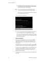
7. Check that network traffic can be routed between the workstation and
the frame.
a. If the workstation supports a network ping, ping the frame. For
example, using Windows NT:
Open a command prompt (DOS window)
In the DOS window, enter:
C:\> PING FRAME’S IP ADDRESS
The results will indicate if the ping reached the frame.
b. If the workstation does not support a network ping, ping the
workstation for the frame serial interface:
In the frame serial command window, enter:
->PING “WORKSTATION’S IP ADDRESS”
The workstation’s IP address must be inside the double quotes. The
results will indicate if the ping reached the workstation.
c. If the network ping failed, there may be a network problem
between the frame and the workstation. To ensure it is not the
frame, check the frame with a point-to-point connection:
Using a crossover Ethernet cable, connect the frame directly to a
workstation. The workstation should be assigned an IP Address on
the same Subnet as the frame. Attempt to load the frame’s web page
from a Browser on this workstation.
8. If the point-to-point connection attempt fails call Customer Service. If
the point-to-point connection attempt succeeds, the problem is
somewhere in the network between the original workstation and the
frame.
a. Check the connectivity to the frame from different locations in the
network to attempt to isolate physical disconnect problems.
b. Check the connectivity to the frame from inside and outside the
frame’s subnet to isolate IP Gateway routing problems.
56
8900NET Instruction Manual
Service
c. Check for possible Ethernet MAC Address collisions.
If the Frame ID Memory chip installed on the rear of the frame is
missing or has failed, the frame adopts the default Ethernet MAC
Address.
If more than one frame in the Network adopts the default Ethernet
MAC Address, there could be address resolution problems. Upon
power up the frame will indicate in the serial port console window,
either:
“MAC ADDRESS IS UNIQUE!” – THE FRAME HAS SUCCESSFULLY
RETRIEVED A UNIQUE ETHERNET MAC ADDRESS FROM THE FRAME ID
MEMORY CHIP
or
“MAC ADDRESS IS DEFAULT!” - THE FRAME IS USING THE DEFAULT
ETHERNET MAC ADDRESS. THE FRAME ID MEMORY CHIP IS MISSING OR
HAS FAILED. CALL GRASS VALLEY GROUP CUSTOMER SERVICE
Cannot modify parameters on Web Page
1. Check if parameters can be set for other modules.
If so, the module may be in a remote lockout state.
a. Check if the LOC/REM – LOCAL jumper on the module is set for
local control only. (Refer to that specific module’s manual for help.)
b. In version 2.0 and later of the 8900NET module software, the web
pages for a module in the remote lockout state will indicate that
module remote control is disabled and the module’s controls on the
web pages will be in read-only mode.
If other modules are not controllable, the entire frame may be in a
remote lockout state. In this state, software updates to the modules and
the 8900NET module are also locked out.
c. Check The 8900NET module’s status page if the frame remote
control is disabled.
If so, flip Switch 3 on the S2 DIP switch block (FRAME CNTRL) to
the enabled setting.
2. If it is only a specific parameter that is read-only, the module may be in
a mode assigning read-only operation to that parameter. Refer to the
module’s instruction manual.
3. If only the 8900NET module is read-only, the 8900NET module may be
in remote lockout mode.
a. Check the 8900NET module’s status page to see if the NET CARD
REMOTE CONTROL status is disabled.
b. If so, flip Switch 8 on the S1 DIP switch block (NM CNTRL) to the
enabled setting.
8900NET Instruction Manual
57
Service
Cannot Connect to the Frame From a VTECS1 VideoFrame Control Panel
1. Check that the frame is powered and configured with a 8900NET
module on the network.
2. Check that the 8900NET module in the frame is loaded with software
version 2 or later.
Version 1 software does not support the control panel connection.
3. Check that the control panel has been properly configured with IP
Address, Gateway IP Address, and Subnet Mask. (Refer to the control
panel’s help feature or instruction manual.)
4. Check that the frame’s correct IP Address has been configured in the
control panel’s frame address.
5. Check that the control panel is physically connected to the network.
a. Check that the control panel is connected to a port on an Ethernet
hub.
b. Check if the L LED (L for link) on the back of the control panel is on.
If the LED indicates no link (off), try a different hub port connection.
If the LED still indicates no link, change the cable.
If the LED still indicates no link, contact VideoFrame.
6. Check that the frame is addressable by the control panel.
a. Check if the T LED (T for transmit) on the back of the control panel
flashes upon the attempt to connect to the frame.
If T does not flash, contact VideoFrame.
b. Check if the R LED (R for receive) on the back of the control panel
flashes upon the attempt to connect to the frame.
If R does not flash, there may be a problem in the network path
between the frame and the control panel.
7. Check that the frame is addressable on the network from a Web
browser, refer to the steps on page 54.
a. Attempt to connect to a different frame.
If successful the problem may be with the original frame or the path
between the control panel and the original frame.
b. Check from a workstation connected to the same Ethernet hub as
the control panel. If unsuccessful, there may be a problem with the
network path between the frame and this hub.
58
8900NET Instruction Manual
Service
Event Messages From the Frame Are Not Being Displayed by NetCentral or
Another SNMP Manager Application
1. Check that the frame is powered on and configured with an 8900NET
module on the Network.
2. Check that the 8900NET module in the frame is loaded with software
version 2.1 or later.
Earlier versions of software do not support SNMP.
3. Check that the SNMP Agent has been installed and configured on the
8900NET module.
View the 8900NET module CONFIGURATION page and note the event configuration parameters, the NET CARD EVENT REPORTS form and REPORT
DESTINATIONS table.
If these are not visible, install the SNMP Agent per the instructions in
the manual.
4. Check that the IP Address and Community Name for the SNMP
Manager has been assigned in the REPORT DESTINATIONS table and is
Active.
8900NET Instruction Manual
•
If there is no entry for the SNMP Manager in the Table, the SNMP
manager’s IP Address and Community name must be entered (see
Network Module Configuration for SNMP on page 30).
•
If the entry for the SNMP Manager is incorrect, it must be corrected,
activated, and the 8900NET module must be rebooted.
•
If the entry has been entered and the Status of the entry is reported
NOT IN SERVICE, the Active operation for that entry must be selected,
applied and the 8900NET module must be rebooted.
•
If the entry has been entered and the Status of the entry is NOT READY,
the entry must be corrected, activated and the 8900NET module
must be rebooted.
•
If the entry has been entered and the Status of the entry is ACTIVE –
PENDING REBOOT, the 8900NET module must be rebooted.
59
Service
5. Check that the particular event has been enabled in the frame.
•
For all events, check that the STATUS switch (Switch 1) on the S2
DIP switch block of the 8900NET module is Enabled.
•
For Module Failure-Fixed events:
Check that the MODULE switch (Switch 5) on the S1 DIP switch
block of the 8900NET module is Enabled, and
Check that the SLOT STATUS REPORTING parameter on the slot’s SLOT
CONFIG page is Enabled.
•
For Power Supply Failure-Fixed events:
Check that the PS1 or PS2 switch (Switch 1 or 2) on the S1 DIP
switch block of the 8900NET module is Enabled, and
Check that the POWER SUPPLY STATUS REPORTING parameter on the
power supply’s CONFIGURATION page is Enabled.
•
For 8900NET module Failure-Fixed events, check that the NET CARD
STATUS REPORTING parameter on the 8900NET module’s CONFIGURATION page is Enabled.
•
For Hardware Switch change events, check that the HARDWARE
SWITCH REPORTING parameter on the 8900NET module’s CONFIGURATION page is Enabled.
•
For Frame Bus Failure-Fixed events:
Check that the FRAME BUS switch (Switch 6) on the S1 DIP switch
block of the 8900NET module is Enabled, and
Check that the FRAME BUS STATUS REPORTING parameter on the
frame’s CONFIGURATION page is Enabled.
•
For Front Cover Removed -Installed events, check that the COVER
STATUS REPORTING parameter on the frame’s CONFIGURATION page is
Enabled.
•
For Frame Bus Failure-Fixed events:
Check that the FRAME BUS switch (Switch 6) on the S1 DIP switch
block of the 8900NET module is Enabled, and
Check that the FRAME BUS STATUS REPORTING parameter on the
frame’s CONFIGURATION page is Enabled.
•
For Cooling Fan Failure-Fixed events:
Check that the FAN switch (Switch 4) on the S1 DIP switch block of
the 8900NET module is Enabled, and
Check that the FAN STATUS REPORTING parameter on the frame’s CONFIGURATION page is Enabled.
•
For Module Health Failure-Fixed events,
Check that the MODULE switch (Switch 5) on the S1 DIP switch
60
8900NET Instruction Manual
Service
block of the 8900NET module is Enabled, and
Check that the MODULE HEALTH REPORTING parameter on the frame’s
CONFIGURATION page is Enabled.
•
Check that the SNMP Manager is properly configured to receive the
Event Messages.
Check that the SNMP Manager has been assigned the same community name as in the frame’s configuration.
6. Check the network connectivity between the SNMP Manager and the
frame as described in the steps on page 54.
8900NET Instruction Manual
61
Functional Description
Functional Description
Refer to the block diagram in Figure 37 while reading the following functional description.
Figure 37. 8900NET Block Diagram
+5 V
+3.3 V
On-board
Regulator
+12 V
Temperature
Sensing
Boot ROM
SDRAM
NVRAM
RS-232
Driver
RS-232 (9-pin D)
10BaseT Ethernet
Ethernet (RJ-45)
Module Health Bus
LEDs
Frame Bus
Microprocessor
Module
Present
Detection
User
Setup
Sw.
SMPTE
Alarm
Alarm
Signal
Bus
Processing
User
Setup
Sw.
M
o
t
h
e
r
b
o
a
r
d
Power Supply
Cells
Module Cells
Ethernet/MAC Address
SMPTE Alarm
(BNC)
SMPTE
Relay
To Fan Assembly
0612-01
Fan Speed
Control and
Rotation
Sensing
Temperature Sensing
Two temperature sensors on the module report to the microprocessor when
they detect:
•
External ambient temperature above 50° C, or
•
Internal frame temperature above 70° C.
The microprocessor will then report a temperature fault.
62
8900NET Instruction Manual
Functional Description
ROM and RAM
Software updates can be made to the 8900NET ROM through the Webbased interface. Non-volatile RAM is provided to store key setup values
when power is cycled.
Ethernet Port
The 10Base-T Ethernet port provides configuration and monitoring access
to the frame, frame modules and the 8900NET module using a Web
browser.
RS-232 Serial Port
The RS-232 port is used to initialize the module with critical network
parameters including a static assigned IP Address. Ethernet MAC address
is stored on a serial EPROM on the frame. (The frame needs both MAC and
IP Addresses.)
Module Health Bus
The Module Health bus connects all the audio/video module cells to the
microprocessor. It is used to report module faults or data errors.
Frame Bus
The Frame Bus provides serial communication to each of the audio/video
modules for remote configuration and monitoring over a network.
Module Present Detection
Module Present lines from cells 1 through 10 and Present/Health lines
from cells 12 and 13 are monitored by the microprocessor using the Module
Present Detection circuitry. For cells 1 through 10, this circuit reports to the
processor whether a module is present and if it supports frame bus communications (control and monitoring). For cells 12 and 13, this circuit
reports if the power supply is present and if it is working properly.
8900NET Instruction Manual
63
Functional Description
Fan Speed Control and Monitor
The fan speed circuit controls the speed of the fans based upon the ambient
temperature in the area in which the frame is located. If the temperature is
30° C or lower, the fans are set to minimum speed. For temperatures above
30° C, the fan speed is set higher as the temperature increases. The fan
speed is set to maximum for ambient temperatures above 40° C. The
control circuit can be overridden so the fans are set to maximum speed,
using a jumper on the board.
On-board Regulator
+12 V supply voltage is regulated on-board to provide +5 V and +3.3 V to
the module.
64
8900NET Instruction Manual
Appendix
Compatibility Matrix
The compatibility matrix in Table 6 lists the modules that can reside in the
8900TFN frame, features that are supported, the module assembly
numbers and how software updates are handled. For the latest information
on any module, software available and the Release Notes and latest
Instruction Manual, visit the Support link on the Grass Valley web site
(refer to Contacting Grass Valley at the beginning of this manual).
Table 6. 8900 Compatibility Matrix
Assembly #
Control &
Monitoring
Support1
Control & Monitoring
Notes2
Software
Update
8931
160169-00
no comm
–
n/a
8936
160170-00
no comm
–
n/a
8941
160171-00
no comm
–
8900_FLOAD-CBL3
671-4853-00
basic status
Id defect, faults not reported
Not upgradeable
full c&m
–
8900_FLOAD-CBL3
Model #
8916
671-4853-01
671-4853-02
671-4795-00
8920DAC
671-4795-01
671-4795-02
Id defect, faults not reported
full c&m
671-4795-03
8920ADC
8920ADT
Id defect, faults not reported
basic status
671-4796-02
671-4796-03
671-6326-00
671-6326-01
8900_FLOAD-CBL3
–
671-4796-00
671-4796-01
Faults not reported
Faults not reported
8900_FLOAD-CBL3
full c&m
–
full c&m
–
8900_FLOAD-CBL3
full c&m
–
8900_FLOAD-CBL3
full c&m
–
8900_FLOAD-CBL3
671-6291-00
8920DMX
671-6291-01
671-6291-02
671-6291-03
8920MUX
8900NET Instruction Manual
671-6290-00
671-6290-01
65
Appendix
Table 6. 8900 Software Compatibility Matrix - (continued)
Model #
Assembly #
671-4798-00
8950DAC
671-4798-01
671-4798-02
671-4798-03
671-4799-00
8950ADC
8960DEC
671-4799-01
Control &
Monitoring
Support1
Control & Monitoring
Notes2
basic status
faults not reported
Software
Update
8900_FLOAD-CBL3
full c&m
–
basic status
faults not reported
8900_FLOAD-CBL3
671-4799-02
full c&m
–
671-4664-00
no comm
misleading status reported
full c&m
–
full c&m
–
8900_FLOAD-CBL3
full c&m
Requires 8900NET v3.2.0
ftp download
671-4664-01
671-4664-03
8900_FLOAD-CBL3
671-4664-04
8960ENC
671-4698-00
671-4698-01
8964DEC
8964ENC
671-6477-00
full c&m
Requires 8900NET v3.2.0
ftp download
8990ARC
671-5246-00
full c&m
–
8900_FLOAD-CBL
full c&m
–
8900_FLOAD-CBL3
full c&m
–
8900_FLOAD-CBL3
8981FS
8981NR
8500 Series
8800 Series
66
671-6471-00
671-5023-00
671-5023-01
671-5023-10
For 8500 and 8800 Series module compatibility see Legacy Module Support on page 27.
1 See
Control and Monitoring Support on page 67 for definitions
2 See
Control and Monitoring Notes on page 67 for definitions
3 See
8900–FLOAD–CBL Assembly on page 67 for information
8900NET Instruction Manual
Compatibility Matrix
Control and Monitoring Support
The following abbreviations are used to indicate the features supported or
not supported by the modules listed in Table 6:
•
No comm — The module does not support any remote control or monitoring functions.
•
Basic status — The module responds to only low-level probe from the
Network module and only returns model number and description.
Fault and signal presence are not reported. No control is supported.
•
Full C&M — The module fully supports the control and monitoring
system. The module reports status of all settings. The module can be
configured remotely.
Control and Monitoring Notes
The following abbreviations are used in Table A-6 to indicate performance
limitations for the listed legacy modules:
•
Comm problem — The module shorts out the frame communication
bus. When the problem module is installed, the NET module cannot
communicate with any of the modules in slots 1 through 10.
•
ID defects — The module is susceptible to ESD (electro-static discharge) damage of the module ID lines. If this damage occurs, the
module will be reported as faulted on the frame status page and software download will not work.
•
Faults not reported — The module may not report an error to the NET
module even though its fault LED is on. The LED gives the correct fault
status.
•
Misleading status reported — The module does not support control
and monitoring but indicates through a motherboard connection that it
does. This module will show up as red on the frame status page even if
it is working correctly.
8900–FLOAD–CBL Assembly
Some modules require a cable assembly and software loading application
for the software update process. This cable assembly and CD–ROM containing update software files can be ordered from Grass Valley. Contact
your Grass Valley sales or service representative about ordering the
8900-FLOAD–CBL assembly.
8900NET Instruction Manual
67
Appendix
68
8900NET Instruction Manual
Index
Numerics
25-pin adaptor 13
A
agent software (SNMP) 30
alarm reporting 18
enables 18
environmental 53
Ethernet 14
F
cable
crossover 14
Ethernet 14
LAN 15
RS-232 11
cable kit 11
Comm 1 port 12
compatibility matrix 65
control panel 8
controller module 9
fan speed 18
FAQ database 2
fault alarms 18
fault condition 26
fault reports
filtering 18
faulty module 54
firewall 19
flow control 12
frame 9, 53
cell 9
upgrade 7
Frame Alarm 11
frame ID 23
frame name and location 28
frame status page 23, 24
frame status reporting 28
frame types 22
frequently asked questions 2
FTP server 37
D
G
daemon 37
default MAC address 23
DIP switch 18
disables 18
disabling fault reports 18
documentation online 2
domain name server 19
gateway IP address 36
Grass Valley Group website 2
B
backplane 10
baud rate 12
block diagram 62
C
E
I
initial configuration 19
Internet Explorer 22
IP Address
setting 19
storage 22
enable SNMP 30
8900NET Instruction Manual
69
Index
J
J102–RS-232 on Video frame 12
J7–RS-232 on Audio frame 12
L
LED indicators 16
link list 24
local area network (LAN) 8
locate module 34
M
MAC (machine) address 23
module
installation 9
module compatibility 65
module slot names 34
N
navigation 24
NET module reboot 36
NetConfig 19
feature 7
software updating 37
Netscape Navigator 22
network addresses 35
network configuration storage 22
network conflicts 23
network identity 19
network parameters 19
establishing 19
network traffic delays 19
NIM LED 16
O
on-board configuration switches 29
online documentation 2
P
parity 12
point-to-point 8, 14
70
point-to-point communication 19
power 53
power supply 9
R
reboot 36
remote control 8
repair depot 54
report enable 18
report enable switches 30
RJ-45 14
RS-232 11, 19
S
service information 54
slot configuration
saving 35
slot memory 35
slot status icons 25
SMPTE Alarm BNC connector 11
SNMP 18, 28
software compatibility 65
software download 37
software download from web 2
software updating
NetConfig 37
stop bits 12
subnet 19
subnet mask 36
supported features 65
switch status 29
T
testpoints 54
troubleshooting 54
U
update status 26
updating 37
upgrade 7
URL 23
8900NET Instruction Manual
Index
V
variable fan speed 18
VideoFrame control panel 8
voltage 53
W
Web browser 22
web site documentation 2
web site FAQ database 2
web site Grass Valley Group 2
web site software download 2
8900NET Instruction Manual
71
Index
72
8900NET Instruction Manual