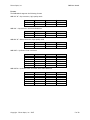
1
User Manual XMR Module January 17, 2007 – Rev 1.2d S. Ackerman Teranex Business Unit / Silicon Optix, Inc 7800 Southland Blvd, Suite 250 Orlando, FL 32809 Voice: 407.858.6000 Fax: 407.858.6001 Silicon Optix, Inc XMR User Manual Table of Contents USER MANUAL ............................................................................................................. 1 TABLE OF CONTENTS .................................................................................................... 2 PREFACE ................................................................................................................... 3 OVERVIEW.................................................................................................................. 4 Filters and Algorithms ................................................................................................. 4 Formats .................................................................................................................. 5 Packages ................................................................................................................. 6 INSTALLING & STARTING................................................................................................ 7 Getting assistance with the XMR .................................................................................... 7 Servicing ................................................................................................................. 7 QUICKSTART GUIDE ...................................................................................................... 8 To install the Teranex XMR modules:............................................................................... 9 Frame Capacity ......................................................................................................... 9 Module Placement in the 2000T3N Kameleon Frame ............................................................ 9 Cabling .................................................................................................................. 12 Power Up ............................................................................................................... 13 Operation Indicator LEDs ............................................................................................ 14 PROCESSING FEATURES ................................................................................................15 Status Menu ............................................................................................................ 15 License Menu........................................................................................................... 16 Setup Menu ............................................................................................................. 17 Aspect Menu............................................................................................................ 19 Proc Amp Control Menu .............................................................................................. 21 Detail Enhance Menu ................................................................................................. 22 Temporal Recursive Filter ........................................................................................... 23 Color Legalizer Menu ................................................................................................. 27 GPI Menu................................................................................................................ 28 E-MEM Menu (Standard) .............................................................................................. 29 E-MEM Menu (Advanced) ............................................................................................. 30 Copyright – Silicon Optix, Inc – 2007 2 of 30 Silicon Optix, Inc XMR User Manual Preface Copyright © 2007 Silicon Optix Incorporated. All rights reserved. Printed in the United States of America All data and information contained in or disclosed by this document is confidential and proprietary information of Teranex Incorporated, and all rights therein are expressly reserved. By accepting this material the recipient agrees that this material and the information contained therein is held in confidence and in trust and will not be used, copied, reproduced in whole or in part, nor its contents revealed in any manner to others without the express written permission of Silicon Optix Incorporated. Information in this document is preliminary and subject to change and does not represent a commitment on the part of Silicon Optix Incorporated. Version 1.0 1.1 1.2d 1.3 1.4 1.5 Date 2006.02.03 2006.02.09 2007.01.17 Comment Draft Release Initial Release By S. Ackerman S. Ackerman S. Ackerman References: XMR_UM.doc Copyright – Silicon Optix, Inc – 2007 3 of 30 Silicon Optix, Inc XMR User Manual Overview Filters and Algorithms PixelMotion™ De-interlacing PixelMotion de-interlacing of video originated material produces perfect progressive frames in preparation for further processing. The processing aperture is adjusted on a pixel-by-pixel basis, which preserves all of the detail of the original interlaced image and eliminates jaggies in the output image. Scene Change Detection Preserves clean cuts between scenes. Upon detecting a cut, the temporal aperture is reduced from 4fields to 2-fields for the first frame in the new scene. This prevents uncorrelated data from being used in the interpolation process at scene boundaries. 3:2 Handling Recognizes and handles the redundant fields inserted by the telecine during 24fps film to 30fps video conversion. By detecting 3:2 sequences it allows for better performance in the de-interlace process by maintaining the full vertical resolution. Aspect Ratio Control Allows selection from standard aspect ratios such as common top & bottom, common sides and anamorphic. Detail Enhancement Is an edge-sharpening filter based on a traditional film compositing technique called "Unsharp Masking." This filter corrects any blurring introduced during image capture, compression or resampling. Noise Reduction Adjustable noise reduction controls offer a greater degree of temporal recursive noise reduction with fewer artifacts. For greater control, the filter operates in both automatic and manual modes. In auto mode, the system analyzes the input and applies the noise reduction setting based on the detected noise and degree of motion in the image. A bias control allows the auto mode aggressiveness to be fine-tuned. In manual mode, users have controls to adjust the recursion for both static and motion areas of the image plus a threshold setting controls the sensitivity of the noise reduction to motion vs. noise. For noise reduction the pixels identified as being in motion are shown with a red overlay. Copyright – Silicon Optix, Inc – 2007 4 of 30 Silicon Optix, Inc XMR User Manual Formats The XMR Module supports the following formats XMR-UPC-4F > Up-conversion, high quality mode Input 480i59.94 480i59.94 Output 720p59.94 1080i59.94 Input 576i50 576i50 Output 720p50 1080i50 Input 576i50 576i50 Output 720p50 1080i50 Input 720p50 1080i50 Output 576i50 576i50 Input 576i50 576i50 720p50 720p50 1080i50 1080i50 Output 720p50 1080i50 576i50 1080i59.94 576i50 720p50 XMR-UNC > Up-conversion with Noise Reduction Input 480i59.94 480i59.94 Output 720p59.94 1080i59.94 XMR-DNC-4F > Down-conversion, high quality mode Input 720p59.94 1080i59.94 Output 480i59.94 480i59.94 XMR-UDCS > Up/Down/Cross-conversion Input 480i59.94 480i59.94 720p59.94 720p59.94 1080i59.94 1080i59.94 Output 720p59.94 1080i59.94 480i59.94 1080i59.94 480i59.94 720p59.94 XMR-UDCSN > Up/Down/Cross-conversion with Noise Reduction Input 480i59.94 480i59.94 720p59.94 720p59.94 1080i59.94 1080i59.94 Copyright – Silicon Optix, Inc – 2007 Output 720p59.94 1080i59.94 480i59.94 1080i59.94 480i59.94 720p59.94 Input 576i50 576i50 720p50 720p50 1080i50 1080i50 Output 720p50 1080i50 576i50 1080i59.94 576i50 720p50 5 of 30 Silicon Optix, Inc XMR User Manual Packages The imageConvert families of applications are available in the following configurations XMR-UPC-4F XMR-UNC XMR-DNC-4F XMR-UDCS XMR-UDCSN XMR Module - High Quality Up-converter Includes: Up-conversion w/ PixelMotion De-interlacing, Aspect Ratio Conversion, Colorspace Conversion, and Detail Enhance. Includes: XMR Module and Rear Interface XMR Module - High Quality Up-converter with Noise Reduction Includes: Up-conversion w/ PixelMotion De-interlacing, Noise Reduction, Aspect Ratio Conversion, Colorspace Conversion, and Detail Enhance. Includes: XMR Module and Rear Interface XMR Module - High Quality Down-converter Includes: Down-conversion, Aspect Ratio Conversion, Colorspace Conversion, and Detail Enhance. Includes: XMR Module and Rear Interface XMR Module - High Quality Up/Down/Cross-converter Includes: Up-conversion, Down-conversion, Cross-conversion, Aspect Ratio Conversion, Colorspace Conversion, and Detail Enhance. Includes: XMR Module and Rear Interface XMR Module - High Quality Up/Down/Cross-converter with Noise Reduction Includes: Up-conversion, Down-conversion, Cross-conversion, Noise Reduction, Aspect Ratio Conversion, Colorspace Conversion, and Detail Enhance. Includes: XMR Module and Rear Interface Copyright – Silicon Optix, Inc – 2007 6 of 30 Silicon Optix, Inc XMR User Manual Installing & Starting Getting assistance with the XMR This manual will help you get started with your Teranex application. features and procedures for the tasks you can perform using this product. It provides an overview of However, if you need further assistance please contact: 24-hr Technical Support Phone: For US & Canada: International: 877.2.TERANEX (877.283.7263) 1.407.858.6000 Technical Support e-mail: [email protected] Technical Support web site: www.teranex.com/support Servicing Only authorized service personnel should open the unit. supply(ies) before servicing. Copyright – Silicon Optix, Inc – 2007 Disconnect AC sources to the power 7 of 30 Silicon Optix, Inc XMR User Manual Quickstart Guide 1. Install the Teranex XMR modules in the frame. Install the XMR-I0-1 Rear I/O Module first, then install the XMR-MOD-1 processor module. For more detailed instructions on slot usage and installation see the sections that follow. 2. Connect the frame to the network and navigate the web browser to the frame. See the 2000NET Instruction Manual for information on configuring your frame IP address and connecting to the network. 3. Navigate to the module you would like to configure and click on the appropriate slot to open configuration links. 4. Click on the Slot Config link on the left side of the page. This page allows you to assign a name to this module. Assigning easily recognized names will help later in the configuration process. 5. Connect signal cables. Configuration will be easier if all of the input signals are connected at this time. 6. Configure the Format and Reference pages. Configure the input and output formats and the reference source. If you have the 2000GEN reference installed in the frame and want to use an external reference signal, set the reference source to External. If not, set the reference source to Internal. 7. Configure the input and output formats and the reference source. If you have the 2000GEN reference installed in the frame and want the Kameleon to work as a frame sync. Copyright – Silicon Optix, Inc – 2007 8 of 30 Silicon Optix, Inc XMR User Manual To install the Teranex XMR modules: 1. Place the XMR-IO-1 rear module in a frame slot and tighten the screws on each side of the rear module, 2. Place the processor module in the corresponding front slot, and 3. Cable the signal ports. Note: All Kameleon modules can be inserted and removed from a 2000 Series Kameleon Frame with power on. Frame Capacity Kameleon modules can be installed in any 2000 Series frame. The one rackunit 2000T1DN frame can hold up to 2 Teranex XMR modules. The three rackunit (3RU) 2000T3N frame can hold up to 6 Teranex XMR modules when the 2000FAN fan sled and two power sleds are installed. Module Placement in the 2000T3N Kameleon Frame There are twelve slot locations in both the front and rear of a 3 RU frame. The 3RU can accommodate up to 6 Teranex XMR Modules. To install a Kameleon module set in the 2000 Series frame: 1. Locate a vacant slot in the rear of the 3 RU frame. Since the XMR-IO-1 rear module takes up two slot spaces, make sure that placement of the rear module will align with available spaces in the front of the frame. See Figure 1, which shows the slots and slot numbers for the chassis. Figure 1 – 3RU Kameleon Chassis (with slot numbers) 2. Insert the XMR-IO-1 rear module into the vacant rear slot of the frame. Figure 2 shows the rear module being inserted into slot 4 of the 3RU Kameleon chassis. Copyright – Silicon Optix, Inc – 2007 9 of 30 Silicon Optix, Inc XMR User Manual Figure 2 – Inserting XMR-IO-1 Rear Module into Slot 4 Note: The image shown above is the XM rear module. An updated image showing the XMR rear module will be added shortly. 3. Verify that the module connector seats properly against the midplane. 4. Using a crossblade screwdriver, tighten the two screw locks to secure the module in the frame. 5. Locate the corresponding front slot (1 -12) in the frame. Since the Rear Module covers two slot spaces, the processor module will always want to be installed in the lower of the two slots covered by the Rear Module. The 3 RU frame front view is illustrated in Figure 3. Figure 3 – 3RU Frame Slots and Slot Numbers Copyright – Silicon Optix, Inc – 2007 10 of 30 Silicon Optix, Inc XMR User Manual 6. With the component side up, insert the processing module in the corresponding front slot (see Figure 4). Note that since the rear module uses up two slot spaces, the processing module will need to be inserted in the lower of these two slots to connect to the rear module correctly. Figure 4 – Inserting XMR-MOD-1 module into Slot 4 Note: The image shown above is the XM module. An updated image showing the XMR module will be added shortly. 7. Verify that the module connector seats properly against the midplane and rear module connector. 8. Press firmly on both ejector tabs to seat the module. Copyright – Silicon Optix, Inc – 2007 11 of 30 Silicon Optix, Inc XMR User Manual Cabling Figure 5 – XMR-IO-1 Rear I/O Module RS-232 – Serial Port connection to the XMR module. This allows a direct interface to the module for doing limited testing and configuration. This port is not normally used. GPIO – This port allows connection of external GPI signals to the XMR module. Loop – Provide a loop out for the input IN 1 - Serial Digital input connection. The connection may be either standard definition (SD) or high definition (HD). Out1 – Serial Digital Output 1. The connection will be either standard definition (SD) or high definition (HD) depending on the output format selected. Out2 – Serial Digital Output 2. The connection will be either standard definition (SD) or high definition (HD) depending on the output format selected. Copyright – Silicon Optix, Inc – 2007 12 of 30 Silicon Optix, Inc XMR User Manual Power Up The front LED indicators (from left to right). FAULT – Red diagnostic LED is off during normal operation COMM – Yellow LED on during remote control communication CONF – Yellow LED on when module is initializing or processing control data PWR – Green diagnostic LED on indicates power OK Inp Prsnt – Input Present – indicates the XMR is receiving an input Inp Stat – Input Status – indicates the XMR is receiving a valid input based on the currently selected input format Inp SD – Input SD – indicates that the XMR is receiving a standard definition input Inp HD – Input HD – indicates that the XMR is receiving a high definition input Aud Prsnt – Audio Present – indicates the XMR is receiving valid embedded audio TC Prsnt – Timecode Present – indicates the XMR is receiving valid timecode CC Prsnt – Closed Caption Present – indicates the XMR is receiving valid closed caption data Note: At present Closed Caption support is only available for 60Hz formats Out SD – Output SD – indicates that the XMR is outputting a standard definition signal Out HD – Output HD – indicates that the XMR is outputting a high definition signal Copyright – Silicon Optix, Inc – 2007 13 of 30 Silicon Optix, Inc XMR User Manual Operation Indicator LEDs Note: The yellow COMM and CONF LEDs are used for the module location function that is enabled using the 2000NET GUI. The module location function causes these LEDs to repeatedly flash concurrently three times followed by an off state of 900 ms duration. LED Indication Condition Fault (red) • Off Normal operation • On continuously Module has detected internal fault • Long flash One of the inputs is missing or is wrong standard • Short flash Errors present in SDI and/or AES/EBU input COMM (yellow) • Off No activity on frame communication bus • Three flash/off pattern Module Location command received from a remote control system • Short flash Activity present on the frame communication bus CONF (yellow) • Off Module is in normal operating mode • Three flash/off pattern Module Location command received from a remote control system • On continuously Module is initializing, changing operating modes or updating firmware. (When solid on along with Fault LED on, board has failed to load data.) PWR (green) • Off No power to module or module’s DC/DC converter failed • On continuously Normal operation, module is powered Copyright – Silicon Optix, Inc – 2007 14 of 30 Processing Features Status Menu The Status Menu provides feedback on the status of: • • • The Input and Reference signal The identification of the Module including part number, serial number, and hardware version The version of software and firmware running on the Module Silicon Optix, Inc XMR_UM 20060209.doc License Menu The License menu will show the package that is currently licensed on the XMR Module. See Packages, on page 6, for a list of the packages available and their descriptions. Copyright 2006 – Silicon Optix, Inc. – All rights reserved. P.16 of 30 Silicon Optix, Inc XMR_UM 20060209.doc Setup Menu Reference - Allows the user to select whether the XMR locks to its input or to the external reference provided by the frame. Closed Caption - Enable processing of Closed Caption data Closed Caption Line - Allows the user to select the line on which closed caption will be output (for 480i59.94 output only). Audio Delay - Allows the user to adjust the audio delay relative to the video processing delay. Copyright 2006 – Silicon Optix, Inc. – All rights reserved. P.17 of 30 Silicon Optix, Inc XMR_UM 20060209.doc Format Menu Input – Select the desired input format Output – Select the desired output format Apply – Press Apply to enable the selected formats App Configuration - Copyright 2006 – Silicon Optix, Inc. – All rights reserved. P.18 of 30 Silicon Optix, Inc XMR_UM 20060209.doc Aspect Menu Current Aspect: The Current Aspect Menu offers the following aspect ratio conversion options as shown in the inset above: • Anamorphic – This mode is similar to common top and bottom in that it ensures that the top and bottom edges of the input aspect ratio match the top and bottom edges of the output aspect ratio. It also, however, stretches the image horizontally to fill the output 16:9 aspect ratio. This mode is designed for use with material that was originally captured with an anamorphic lens, thereby generating an output image with correct geometry when stretched horizontally to 16:9. When used with standard 4:3 material, it will have the effect of stretching the material horizontally causing circles to appear as ovals, etc. • Common Top - Ensures that the top and bottom edges of the input image match the top and bottom edges of the output aspect ratio. For example, if the input aspect ratio were 4:3 and it was passed on to a 16:9 display using the common top and bottom method, the original 4:3 image would appear centered in the 16:9 display with black bars, or pillars, on the left and right side. • Common Side - Ensures that the left and right edges of the input image match the left and right edge of the output aspect ratio. For example, if the input aspect ratio is 4:3 and the output aspect ratio is 16:9, the left and right edges of the input image are stretched to match the left and right edges of the output. In order to maintain correct geometry of the image, the input image is then stretched vertically as well. This has the same result as zooming in on the image. While this method maintains correct geometry and fills the entire output display, it also results in an overall lose of approximately 33.33% of the input information in the vertical domain. This loss of information is split evenly between the top and bottom of the image. Copyright 2006 – Silicon Optix, Inc. – All rights reserved. P.19 of 30 Silicon Optix, Inc XMR_UM 20060209.doc Zoom/Crop – This function, when selected, will zoom the image by 3-pixels and then crop the image by 3-pixels. This purpose of this function is to allow video disturbances that may arise on the top or bottom edge of an image or on the left or right side of an image to be corrected. Indexing On – Enable support for RP186. Note: This command is only available with a 576i50 input Edge Trim – This control adjusts the amount of border cropping that is performed on the image in the horizontal (X trim) and / or vertical (Y trim) directions. It is adjustable from 0-to-500 pixels In the horizontal domain and 0-to-500 lines in the vertical domain. Copyright 2006 – Silicon Optix, Inc. – All rights reserved. P.20 of 30 Silicon Optix, Inc XMR_UM 20060209.doc Proc Amp Control Menu Video Gain Enabled – Enables the Video Gain Adjustment. Video Gain – Sets the overall amplitude of the output video signal. Once the adjustment is made, Press Apply to enable the selected adjustment. The range of the control is +6.00dB to –6.00dB. Black Level Enabled – Enables the Black Level Adjustment. Black Level – Adjusts the black level of the output video signal. Once the adjustment is made, Press Apply to enable the selected adjustment. The range of the control is +30 IRE to –30 IRE. Hue Enabled – Enables the Hue Adjustment. Hue – Adjusts the phase of the output video signal. Once the adjustment is made, Press Apply to enable the selected adjustment. The range of the control is -179.0 degrees to +178.0 degrees. Saturation Enabled – Enables the Saturation Adjustment. Saturation – Adjusts the Chroma Saturation of the output video signal. Once the adjustment is made, Press Apply to enable the selected adjustment. The range is +6.0 to –6.0dB. Copyright 2006 – Silicon Optix, Inc. – All rights reserved. P.21 of 30 Silicon Optix, Inc XMR_UM 20060209.doc Detail Enhance Menu Based on a traditional film compositing technique called "Unsharp Masking." This edge-sharpening filter allows for both positive and negative aperture correction. Unsahrp Mask Enable – Enables the Detail Enhancement Adjustment. Unsharp Mask Slider - Allows the user to enhance the detail in the image. The range of the control is 0 to 100 Sharpness Enable - Enables the Sharpness Adjustment. Sharpness Slider - Allows the user to sharpen the detail in the image. The range of the control is 0 to 100 Copyright 2006 – Silicon Optix, Inc. – All rights reserved. P.22 of 30 Silicon Optix, Inc XMR_UM 20060209.doc Temporal Recursive Filter This Noise Reducer is a motion adaptive temporal recursive filter that works well in removing random and Gaussian noise. Each pixel is labeled as motion, no motion, or noise. Each of these classes of pixels is treated differently in the noise reduction process. For pixels in which there is no motion, lowlevel Gaussian noise may be reduced via temporal processing by a weighted averaging over successive frames. For pixels labeled as random noise, spatial processing replaces these pixels. Pixels labeled as being “in motion” are retained “as is” to avoid artifacts that may be introduced through temporal processing. The Temporal Recursive Filter also has an “Auto” mode for providing better operation in all modes. Enabled – Enables the Temporal Recursive Filter. Red Overlay – When turned On, the system superimposes a red overlay onto areas in the input image where the temporal recursive filter will identify motion. The red overlay would display what the system is not ‘attacking’ or filtering. Copyright 2006 – Silicon Optix, Inc. – All rights reserved. P.23 of 30 Silicon Optix, Inc XMR_UM 20060209.doc • In the Temporal Recursive Filter, the red overlay will show the pixels in the image that have been determined to be in motion. In Auto mode, these pixels will not have any noise reduction applied to them. In manual mode they will have noise reduction applied according to the setting of the Motion, Historical Percentage slider. • In Auto mode the red overlay will help to identify the pixels in the image, which are being processed by the temporal recursive filter. In manual mode it can help in adjusting the Distance control. The Dist Button is used to set the distance threshold to determine the sensitivity to motion between the current frame and historical frames. This threshold represents a percentage of the current pixel value that the historical pixel value must be within in order to be considered “unchanged”. The Distance control should be set to a point where only pixels that are actually in motion are colored red. This will allow noise to be correctly processed as noise rather than motion. Auto Mode Auto– Engages a feedback controller that dynamically sets the distance, no motion and motion sliders based and noise and motion measurement extracted from the scene. Setting this button will disengage the distance, no motion and motion adjustments. Bias (Only used in Auto Mode) – Adjusts the noise set point in the temporal recursive controller. The higher the bias, the more aggressive the controller is towards noise in the scene. The lower the bias, the more sensitive the controller is towards motion in the scene. Once the adjustment is made, Press Apply to enable the selected adjustment. The range of the bias control is -6 to +6, with a nominal setting of 0. Copyright 2006 – Silicon Optix, Inc. – All rights reserved. P.24 of 30 Silicon Optix, Inc XMR_UM 20060209.doc Manual Mode Distance - Sets the distance threshold to determine the sensitivity to motion between the current frame and historical frames. This threshold represents a percentage of the current pixel value that the historical pixel value must be within in order to be considered “unchanged”. The Dist button is fully operational in this mode so the user can identify the motion sensitivity of this control, and better control it’s setting. Once the adjustment is made, Press Apply to enable the selected adjustment. The range of the control is 0 to 40. The nominal value for this Dist threshold is 15. A Dist setting of 0 will detect motion at every pixel, the impact being that no filtering will occur. A Dist setting of 40 will be less sensitive to motion, temporally filtering every pixel, which may result in blurring of any objects/areas that are in motion. In other words, if Dist is too low, it thinks everything is moving, therefore no filtering. If Dist is too high, it thinks nothing is moving, therefore filtering everything Historical Percentage: No Motion - Sets the historical weighting factor for areas in the frame where no motion has been detected. Once the adjustment is made, Press Apply to enable the selected adjustment. The range of the control is 0 to 100. A setting of 100 forces the filter to use only historical data in areas where no motion has been detected. A setting of 0 forces the filter to use only current data in areas where no motion has been detected. The nominal setting for this is 75. Copyright 2006 – Silicon Optix, Inc. – All rights reserved. P.25 of 30 Silicon Optix, Inc XMR_UM 20060209.doc Historical Percentage: Motion - Sets the historical weighting factor for areas in the frame where motion has been detected. Once the adjustment is made, Press Apply to enable the selected adjustment. The range of the control is 0 to 100. A setting of 100 forces the filter to use only historical data in areas where motion has been detected. A setting of 0 forces the filter to use only current data in areas where motion has been detected. The nominal setting for this slider is 0. Copyright 2006 – Silicon Optix, Inc. – All rights reserved. P.26 of 30 Silicon Optix, Inc XMR_UM 20060209.doc Color Legalizer Menu Luma Limit High – allows the users to set the upper limit for the luminance portion of the signal. The range of adjustment is Luma Limit Low – allows the users to set the lower limit for the luminance portion of the signal. The range of adjustment is Chroma Limit High – allows the users to set the upper limit for the chroma portion of the signal. The range of adjustment is Chroma Limit Low – allows the users to set the lower limit for the chroma portion of the signal. The range of adjustment is Copyright 2006 – Silicon Optix, Inc. – All rights reserved. P.27 of 30 Silicon Optix, Inc XMR_UM 20060209.doc GPI Menu GPI Inputs Enabled – enables the selected GPI E-MEM – Allows the user to assign an E-MEM to one of the 3 GPI’s Pin-out Designations for 9-pin D-Style Female GPI connector PINS PINS SIGNALS 1 GPI INPUT #3 5&6 System Ground 2 GPI INPUT #2 7 Not Connected 3 GPI INPUT #1 4, 7-9 Reserved Copyright 2006 – Silicon Optix, Inc. – All rights reserved. SIGNALS P.28 of 30 Silicon Optix, Inc XMR_UM 20060209.doc E-MEM Menu (Standard) E-MEM 1 – 10 – Saves the currently selected setting The user may name each Preset. Save – Saves the selected Preset Recall – Recalls the selected Preset. Copyright 2006 – Silicon Optix, Inc. – All rights reserved. P.29 of 30 Silicon Optix, Inc XMR_UM 20060209.doc E-MEM Menu (Advanced) Local Operations • E-MEM 1 – 10 – Saves the currently selected setting • The user may name each Preset. • Save – Saves the selected Preset • Recall – Recalls the selected Preset. File Operations • SaveTo – Allows the user to save the currently selected e-mem file to an external PC • Load From – Allows the user to load an e-mem file from an external PC Copyright 2006 – Silicon Optix, Inc. – All rights reserved. P.30 of 30