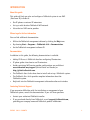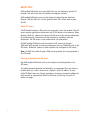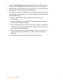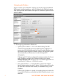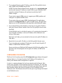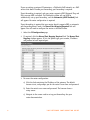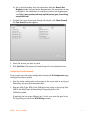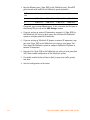
1
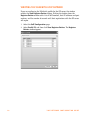
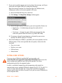
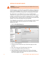
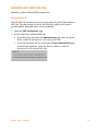
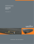
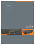
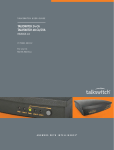
TA L K S W I TC H D O C U M E N TAT I O N
VOIP NETWORK
CONFIGURATION GUIDE
RELEASE 6.10
C T.T S 0 0 5 . 0 0 2 6 0 6
ANSWERS WITH INTELLIGENCE
®
INTRODUCTION
About this guide
This guide will help you plan and configure a TalkSwitch system to use VoIP
(Voice over IP) in order to:
•
Use IP phones as external IP extensions.
•
Set up a multi-location TalkSwitch VoIP network.
•
Subscribe to a VoIP service provider.
Where to go for further information
You can find additional documentation:
•
Within the TalkSwitch management software by clicking the Help icons.
•
By choosing Start > Programs > TalkSwitch 6.10 > Documentation.
•
On the TalkSwitch management software CD.
Documentation
In addition to this guide, the following documentation is available:
•
Adding IP Phones to TalkSwitch describes configuring IP extensions.
•
IP phone guides show how to use IP extensions.
•
Guides containing VoIP service provider configurations are available at
www.talkswitch.com/support (United States and Canada) or
http://global.talkswitch.com.
•
The TalkSwitch Start Guide shows how to install and set up a TalkSwitch system.
•
The TalkSwitch User Guide provides complete information about the
TalkSwitch system.
•
Help built into the TalkSwitch management software describes each window.
Contacting Technical Support
If you encounter difficulties with the installation or management of your
TalkSwitch system, consult the documentation. If you still have questions:
•
Contact your authorized TalkSwitch reseller.
•
If you purchased directly from TalkSwitch, e-mail [email protected],
providing your company name and TalkSwitch product information.
EVERY CALL COUNTS
1
ABOUT VOIP
VoIP-enabled TalkSwitch units route VoIP calls over the Internet or private IP
network, and other calls over the traditional telephone network.
VoIP-enabled TalkSwitch units use the industry-standard Session Initiation
Protocol (SIP) for VoIP calls. In this guide the term SIP is often used in place
of VoIP.
About SIP servers
A VoIP network requires a SIP server to manage calls across the network. The SIP
server contains registration information for all SIP devices in the network. When
making a VoIP call, a device will contact the SIP server to get contact information
for the destination. The device will then establish a connection with the
destination. The SIP server is also involved with call termination.
All VoIP-enabled TalkSwitch units have built-in SIP servers to manage a
TalkSwitch VoIP network, but you must designate only one TalkSwitch unit as the
SIP server. TalkSwitch systems at other locations are configured as SIP clients.
Note: For VoIP calls made through a VoIP service provider, the service provider is
the SIP server.
Selecting a location for the SIP server
Any VoIP-enabled TalkSwitch unit on the network can be designated as the
SIP server.
To simplify network operation and reliability, we recommend that you choose a
location that has a static, rather than a dynamic, public IP address. A static
public IP address does not change, providing a consistent connection address for
each location to communicate with the SIP server. See Setting the public IP
address on page 6.
2
VOIP NETWORK CONFIGURATION GUIDE
CONNECTING TO A NETWORK
Each location requires a high-speed connection to the Internet or private IP
network that is sufficient for VoIP calls. This is required for a location using an
external IP extension, TalkSwitch VoIP network, or service provider VoIP network.
Connecting to local and IP networks
Set up a LAN (local area network) with an Ethernet switch, router, and modem or
gateway. The Ethernet switch can be integrated into the router. Connect a
computer to the LAN for configuring the TalkSwitch unit and other equipment.
Optional IP phones can be connected as well. Use the provided RJ-45 Ethernet
cable to connect the TalkSwitch unit to the LAN. To ensure reliability, all
equipment should be connected to a UPS (uninterrupted power supply).
Figure 1: Local and IP network setup
Connecting a VoIP gateway
In order to connect to a TalkSwitch VoIP network, a location can use a SIPcompatible VoIP gateway instead of a VoIP-enabled TalkSwitch unit. For example,
the Mediatrix® 2102 is a TalkSwitch-certified third-party VoIP gateway that is
suitable for small branch offices or teleworkers.
Confirming network capacity
Ensure the LAN in each location has a reliable high-speed broadband connection
to the Internet or private IP network. The quality of VoIP calls, especially on
mixed voice and data networks, depends on high data-transfer rates across the
network. The limiting factor is the upstream bandwidth to the ISP (Internet
Service Provider). ‘Lite’ broadband connections (128 Kbps or less) are not suitable
for simultaneous voice and data traffic.
To test the VoIP call capacity based on your Internet connection speed, perform
the test available on our website at: www.talkswitch.com/voip/voip_test.asp.
EVERY CALL COUNTS
3
CONFIGURING IP ADDRESSES
Starting the TalkSwitch management software
1. Double-click the TalkSwitch Configuration 6.10 icon on your desktop. You
can also select Start > Programs > TalkSwitch 6.10 > TalkSwitch
Configuration 6.10. The TalkSwitch Management Software window
appears, and the software attempts to detect your TalkSwitch unit.
2. Select your language. You can select English, Français or Español.
3. Once the software detects your TalkSwitch unit, click Configure AutoDetected TalkSwitch System. The About page appears.
If the software was unable to detect your TalkSwitch unit, follow the
procedures in Step 3 — Open the TalkSwitch Management Software in the
TalkSwitch Start Guide.
Setting the system IP settings
Each TalkSwitch unit must be configured with a local IP address. These addresses
are used to direct VoIP calls to the appropriate location.
X
4
Y
Z
VOIP NETWORK CONFIGURATION GUIDE
1. Select the IP Configuration page. By default, Obtain IP and DNS information
automatically is selected and the area shows IP addresses from the router.
2. Change Obtain IP and DNS information automatically to Use configured IP and
DNS information in order to lock in the IP addresses.
3. In some cases, the System IP Settings area may be blank because your router
has not delivered the IP addresses. If so, enter the following IP addresses from
your LAN administrator:
a) Enter a static IP address for each TalkSwitch unit in the Unit IP
address boxes.
b) Enter the Subnet mask for the LAN. This address determines the subnet
that the unit IP addresses belong to.
c) Enter the IP address of the Default gateway on your network. A gateway is
a hardware device that connects the office network to the Internet. The
router may act as default gateway.
d) Enter the IP address of the Preferred DNS server. DNS is a service that is
used to resolve a domain name to an IP address. The router may act as
DNS server.
e) If applicable, enter the IP address of the Alternate DNS server.
EVERY CALL COUNTS
5
Setting the public IP address
If you are setting up an external IP extension, or the SIP server of a TalkSwitch
VoIP network, you must configure a public IP address for the TalkSwitch system.
Some service provider VoIP networks also require the TalkSwitch system to have a
public IP address.
X
Z
Y
1. Set the Type of public address. Choices are:
•
Dynamic public IP address — This is the default setting. Your ISP
(Internet Service Provider) will assign different public IP addresses to
your location. The TalkSwitch system will check its public IP address every
few minutes. When the public IP address changes, the TalkSwitch system
will automatically use the new one, in order to manage VoIP
calls properly.
If Dynamic public IP address is selected, the window completes the Current
public IP address, and sets Public IP address-checker server name to
checkip.talkswitch.com. This server runs an IP checker application that
provides public IP addresses to TalkSwitch systems.
•
Static public IP address — A static IP address is fixed. Your Internet
Service Provider assigns the static IP address. If this location will have the
SIP server for a TalkSwitch VoIP network, we recommend using a static
IP address.
If Static public IP address is selected, the window allows you to enter the
Current public IP address, and disables the Public IP address-checker server
name box.
6
VOIP NETWORK CONFIGURATION GUIDE
2. If you selected Dynamic public IP address, enter the Fully qualified domain
name (FQDN). Get the FQDN from your ISP.
A DDNS (Dynamic Domain Name Service) provider such as www.dyndns.com
matches your dynamic IP addresses to your FQDN, so your TalkSwitch VoIP
network or external IP phones will continue to work when the IP
address changes.
If your router supports DDNS, ensure it supports your DDNS provider, and
configure it to update the DNS servers.
If your router does not support DDNS, download one of the applications
specified on www.dyndns.com. To update the DNS servers, the application
needs to run on a PC connected to the same LAN as the TalkSwitch system.
3. If you selected Static public IP address, enter the Current public IP address
from your Internet Service Provider. Leave the Fully qualified domain name
box blank.
If the TalkSwitch unit is not behind a router, or if a private virtual network is
used, the public IP address is the local IP address of the TalkSwitch unit
acting as local proxy.
Note that it will take up to one minute for the new static public IP address to
take effect.
4. Record the Current public IP address or the Fully qualified domain name.
If you are setting up an external IP extension, you will need the public IP
address or FQDN of the TalkSwitch system.
If you are setting up a TalkSwitch VoIP network, the TalkSwitch profiles of the
SIP clients must be configured with the public IP address or FQDN of the
SIP server.
CONFIGURING THE ROUTER
The Router Port Forwarding area of the IP Configuration page displays the type of
gateway device (i.e. the type of router), the IP address of the gateway (i.e.
router), and whether router configuration is required.
A router is a gateway between the local area network and the Internet. Most
routers have a firewall to block unwanted data from the Internet. For voice data
to reach the TalkSwitch system through the firewall, port forwarding is required.
Port forwarding allows the router to map ports to the IP addresses of the
TalkSwitch units. Valid Internet data will use the ports to go through the firewall
to the TalkSwitch units.
EVERY CALL COUNTS
7
If you are setting up external IP extensions, a TalkSwitch VoIP network, or a VoIP
service that doesn’t handle port forwarding, port forwarding is required.
If port forwarding is required, and your router supports uPNP (Universal Plug and
Play), ensure uPNP is enabled. The TalkSwitch system will use uPNP to
automatically set up port forwarding, and the Automatic (uPNP Enabled) link
will appear. No router configuration is required.
If port forwarding is required but your router doesn’t support uPNP, or automatic
port forwarding doesn’t work, the Manual Port Mapping Required link will
appear. You will need to configure the router as described below.
1. Select the IP Configuration page.
2. If required, click the Manual Port Mapping Required link. The Manual Port
Mapping window appears. It lists the packet type, port number, IP address
and protocol of each required port.
3. To access the router configuration:
a) Click the link containing the IP address of the gateway. The default
browser starts, and prompts you for the router’s user name and password.
b) Enter the router’s user name and password. The browser shows a
setup screen.
c) Navigate to the screen used to set up port forwarding. See your
router documentation.
8
VOIP NETWORK CONFIGURATION GUIDE
d) Set up port forwarding using the information from the Manual Port
Mapping window. See your router documentation for instructions on how
to map ports. For information on configuring routers and mapping ports,
visit http://www.portforward.com/english/routers/port_forwarding/
routerindex.htm.
4. To check the status of each port through the firewall, click Check Firewall.
The Test Firewall window appears.
5. Select the services you want to check.
6. Click Test Ports. The system will check the ports for the selected services.
Configuring the router manually
If you cannot access the router configuration through the IP Configuration page,
configure the router manually.
1. Open the router configuration and navigate to the screen used to set up port
forwarding. See your router documentation.
2. Map port 5060 (Type: UDP) to the TalkSwitch unit acting as local proxy. Port
5060 is the default port for forwarding SIP signaling data to the
TalkSwitch system.
If required, you can map a different port. In this case, enter the port in the
SIP signalling port box of the VoIP Settings window.
EVERY CALL COUNTS
9
3. Map the following ports (Type: UDP) to the TalkSwitch units. These RTP
ports forward voice traffic to the TalkSwitch system by default.
VoIP Lines/
Unit
Unit 1
Unit 2
Unit 3
Unit 4
4
6000–6006
6010–6016
6020–6026
6030–6036
8
6100–6114
6200–6214
6300–6314
6400–6414
If required, you can map different ports. In this case enter the first port in
the Starting RTP port box of the VoIP Settings window.
4. If you are setting up external IP extensions, map port 69 (Type: UDP) to
the TalkSwitch unit acting as local proxy. Port 69 allows the TalkSwitch
system to configure external IP extensions.
5. If you are setting up TalkSwitch IP phones as external IP extensions, map
port 8484 (Type: TCP) to the TalkSwitch unit acting as local proxy. Port
8484 allows the TalkSwitch system to configure TalkSwitch IP phones as
external IP extensions.
6. Map port 9393 (Type: TCP) to the TalkSwitch unit acting as local proxy. Port
9393 allows remote configuration of the TalkSwitch system.
7. If available, enable Quality of Service (QoS) to give voice traffic priority
over data.
8. Save the configuration to the router.
10
VOIP NETWORK CONFIGURATION GUIDE
EXTERNAL IP EXTENSIONS
Warning: Calls to an emergency service number (e.g. 911) using an external
IP extension will not send the correct address to the emergency operator.
We strongly recommend that you apply a warning label to any external IP
extension stating:
1. Calls to emergency services should not be placed from this phone.
2. If an emergency call is made from this phone, you must provide your
address to the emergency operator.
An external IP extension is an IP phone located outside the office. It is configured
as a local extension of a TalkSwitch system, but connects to the system over the
Internet or private data network. A user can receive or place a call with their
external IP extension through the TalkSwitch unit to the standard telephone
network, or to a VoIP network. An external IP extension requires at least one
VoIP-enabled TalkSwitch unit at the office.
For example, the following illustration shows external IP extension 151 at a home
office, and 152 at a branch office. The external IP extensions connect to the
TalkSwitch unit at the main office over the Internet. In this example, a user can
receive or place a call with their external IP extension through the TalkSwitch
unit to the standard telephone network.
Figure 2: External IP extensions
Before proceeding, ensure you have:
•
Connected the TalkSwitch system at each location to a network (see page 3).
•
Configured local and public IP addresses (page 4).
•
Configured the router (page 7).
EVERY CALL COUNTS
11
To set up an external IP extension, use the following steps:
1. Add the external IP extension, as described in Adding IP Phones to TalkSwitch.
Procedures are available for adding TalkSwitch, Polycom, Grandstream,
Counterpath and selected other phones (depending on the market).
2. Verify operation of the external IP extension:
a) Select the Local Extension/Fax page.
b) Select the external IP extension.
c) Confirm Registered is Yes, and the Phone URL appears in the IP Extension
Details area.
3. Optionally, perform advanced VoIP configuration:
a) All VoIP lines are shared by default. You can reserve VoIP lines for the
external IP extensions. See Reserving VoIP lines on page 26.
b) External IP extensions will use the preferred codec selected for the
TalkSwitch profile. The default preferred codec is G.729. You can select the
Preferred codec for the TalkSwitch profile. See Setting codec options on
page 21.
12
VOIP NETWORK CONFIGURATION GUIDE
TALKSWITCH VOIP NETWORK
A TalkSwitch VoIP network has at least one SIP device at each location. A SIP
device is a VoIP-enabled TalkSwitch unit, IP telephone or SIP gateway. One
TalkSwitch unit in the network acts as the SIP server. The other SIP devices are
SIP clients.
A user, auto attendant or call cascade can dial a three-digit VoIP number (ranging
from 250 to 299) to reach an extension, auto attendant or voice mailbox at
any location.
For example, the following illustration shows a TalkSwitch VoIP network with two
locations. Calls between the offices are routed over the Internet, and local calls
are routed over the traditional telephone network.
Figure 3: TalkSwitch VoIP network
Five VoIP numbers are assigned to San Francisco (251 to 255), and nine are
assigned to New York (261 to 269). These VoIP numbers can be dialed directly
from any extension, auto attendant or call cascade in the network.
The TalkSwitch unit in the San Francisco office has a static public IP address, so is
designated as the SIP server. The TalkSwitch unit in New York is a SIP client.
Before proceeding, ensure you have:
•
Connected the TalkSwitch system at each location to a network (see page 3).
•
Configured local and public IP addresses (page 4).
•
Configured the router (page 7).
EVERY CALL COUNTS
13
SETTING UP A TALKSWITCH PROFILE FOR THE SIP SERVER
The TalkSwitch profile for the SIP server shows registration details and contains
authentication information.
1. Start the TalkSwitch management software, and connect to the TalkSwitch
system that will act as the SIP server.
2. Select the VoIP Configuration page.
3. Select Profile TS, which is for configuring the TalkSwitch profile.
_
Y
Z
[
\
]
^
4. Select the This TalkSwitch location is the proxy/registrar check box.
5. Set Registrar authentication to Yes (digest). This restricts access and allows
only authorized devices to connect.
6. Enter a User/account name. All SIP clients must use this name.
7. Enter a Password. All SIP clients must use this password.
8. If you configured the router with non-default ports:
a) Choose Options > VoIP Trunking. The VoIP Settings window appears.
b) Set the SIP Signalling Port and/or Starting RTP Port as required.
14
VOIP NETWORK CONFIGURATION GUIDE
SETTING UP A TALKSWITCH PROFILE FOR A SIP CLIENT
The TalkSwitch profile for a SIP client contains registration details and
authentication information.
1. Start the TalkSwitch management software, and connect to the TalkSwitch
system that will act as the SIP client.
2. Select the VoIP Configuration page.
3. Select Profile TS, which is for configuring the TalkSwitch profile.
Y
Z
[
\
]
^
4. Leave the This TalkSwitch location is the proxy/registrar check box cleared.
5. Enter the Current public IP address or Fully qualified domain name (FQDN) of
the SIP server into the Proxy/registrar server name box.
If the SIP server is using a non-default SIP signalling port (i.e. if the SIP server
is not using 5060 as the SIP signalling port), specify the port number after a
colon at the end of the public IP address or FQDN (e.g. 123.45.67.89:3456).
6. Enter the User/account name from the SIP server. All SIP clients must use
this name.
7. Enter the Password from the SIP server. All SIP clients must use this password.
EVERY CALL COUNTS
15
CONFIGURING VOIP NUMBERS FOR A TALKSWITCH
VOIP NETWORK
A VoIP number is like a telephone number, and is used to dial a TalkSwitch system
at a particular location. Each VoIP number must be unique (i.e. only used at
one location).
VoIP numbers 250 to 299 permit direct dialing from any extension, auto
attendant or call cascade to any extension, auto attendant or voice mailbox in the
TalkSwitch VoIP network. No line hunt group number is required. Longer VoIP
numbers can also be used, but the user must first dial a line hunt group number.
To assist in assigning VoIP numbers for your network, use the Appendix A —
TalkSwitch VoIP network administration form on page 28.
1. Select the VoIP Numbers page.
Z
Y
[
\
X
]
2. Select a VoIP number slot.
3. Select the Activate VoIP Number check box.
4. Set the VoIP profile to TalkSwitch.
5. Enter the VoIP number into the Phone number box.
6. Set up call handling for the VoIP number. For more information, click the
Help icon (
) in the Call Handling area.
7. Repeat steps 2 to 6 for each additional VoIP number.
16
VOIP NETWORK CONFIGURATION GUIDE
SETTING UP LINE HUNT GROUPS
IMPORTANT: Ensure at least one line hunt group uses telephone lines that can
reach emergency services.
If a VoIP-enabled TalkSwitch unit is present, line hunt group 88 uses the
TalkSwitch VoIP network by default, and the other line hunt groups use telephone
lines. You can modify these default settings as described on page 24.
Note that the user does not have to dial the line hunt group number before VoIP
numbers 250–299: these automatically use the TalkSwitch VoIP network.
If 50 VoIP numbers aren’t enough for the network, you can set up longer VoIP
numbers. To reach a longer VoIP number, the user will first dial a line hunt
group number.
A local extension can be restricted to a set of line hunt groups in order to control
access to VoIP networks. See Hunt group permissions in Chapter 2 of the
TalkSwitch User Guide.
ADVANCED VOIP CONFIGURATION
Optionally, perform advanced VoIP configuration.
1. The default preferred codec is G.729. You can select the Preferred codec for the
TalkSwitch profile. All locations must use the same codec. See Setting codec
options on page 21.
2. VoIP calls use extension names for caller ID by default. You can set the source
for VoIP caller ID at each location. The same setting will be used by the
TalkSwitch profile and all service provider profiles. See Setting up caller ID on
page 25.
3. All VoIP lines are shared by default. You can reserve VoIP lines for the
TalkSwitch profile at each location. See Reserving VoIP lines on page 26.
SAVING SETTINGS TO TALKSWITCH
To transfer settings from your computer to the TalkSwitch system, choose File >
Save. A window appears indicating the configuration is being sent.
EVERY CALL COUNTS
17
VERIFYING THE TALKSWITCH VOIP NETWORK
If you are configuring the TalkSwitch profile for the SIP server, the window
enables the View Registrar Entries button. Clicking the button shows the
Registrar Entries window with a list of VoIP numbers, their IP addresses and port
numbers, and the number of seconds until their registrations with the SIP server
will expire.
1. Select the VoIP Configuration page.
2. Select Profile TS, and then click View Registrar Entries. The Registrar
Entries window appears.
18
VOIP NETWORK CONFIGURATION GUIDE
SERVICE PROVIDER VOIP NETWORK
Using a service provider VoIP network requires at least one VoIP-enabled
TalkSwitch unit. The service provider acts as the SIP server. The service provider
assigns the VoIP numbers and VoIP configuration parameters.
For example, the following illustration shows a service provider VoIP network.
Figure 4: Service provider VoIP network
To reach an outside party, the user dials the line hunt group number associated
with the service provider profile, and then dials the phone number. The
TalkSwitch unit routes the call over the Internet to the service provider. If the
outside party doesn’t use the same service provider, they are connected over the
standard telephone network. If the outside party does use the same service
provider, they are connected over the Internet.
To reach a local extension, an outside party dials the VoIP number that was
assigned to the TalkSwitch system by the service provider. The call is routed
through the telephone network to the service provider. The service provider
routes the call over the Internet to the TalkSwitch system, which directs the call
to the local extension.
Before proceeding, ensure you have:
•
Connected the TalkSwitch system at each location to a network (see page 3).
•
Configured local IP addresses (page 4), and public IP addresses if required.
•
Configured the router (page 7).
EVERY CALL COUNTS
19
SETTING UP A SERVICE PROVIDER PROFILE
If you are using a TalkSwitch-certified VoIP service provider, visit
www.talkswitch.com/support/ServiceConfigurationGuides.asp to access the
service configuration guide for your VoIP service provider. Otherwise use the
procedures in this section.
A service provider profile contains the registration details for connecting to the
service provider’s SIP server.
1. Start the TalkSwitch management software.
2. Select the VoIP Configuration page.
3. Select a Profile (SP 1 to SP 4), which are for configuring service
provider profiles.
[
Y
^
Z
]
\
_
4. Select the Activate Profile check box.
5. Enter the Profile name. The default profile name is Service provider n (e.g.
Service provider 1).
6. If your service provider requires you to register using your private IP address,
select the Disable public IP address substitution check box.
20
VOIP NETWORK CONFIGURATION GUIDE
7. If your service provider requires you to set up keep alive messages, and if your
router does not support uPNP, set up keep alive messages.
Keep alive messages maintain the connection from the TalkSwitch unit,
through your router, to the service provider’s SIP server.
a) Select the Enable NAT keep alives check box.
b) Click Settings. The Keep Alive Settings window appears.
c) Select the type of ping, as directed by your service provider. Choices are:
•
Simple ping — A standard ping message that works with all
SIP servers.
•
Nortel ping — A longer but more reliable ping message that only
works with specific Nortel SIP servers (e.g. Nortel MCS 5200).
d) If necessary, change the ping frequency, as directed by your service
provider. The default setting is 45 seconds.
8. Enter the IP addresses or FQDNs, as provided by the service provider, into the
following boxes. If the service provider does not specify a value, leave the
box blank.
•
Proxy server name
•
Registrar server name
•
Outbound proxy
•
Realm/domain
SETTING CODEC OPTIONS
If you are using a TalkSwitch-certified VoIP service provider, visit
www.talkswitch.com/support/ServiceConfigurationGuides.asp to access the
service configuration guide for your VoIP service provider. The service
configuration guide lists the supported codecs.
A codec is a method of compressing and decompressing audio signals for
communication across a network. TalkSwitch supports the G.729, G.726 and G.711
(µ-law or A-law) codecs for VoIP calls. If your service provider or equipment
requires specific codecs for VoIP or Fax over IP calls, you can restrict TalkSwitch to
use the required codec.
EVERY CALL COUNTS
21
The Codec Options window allows you to select the codecs that your system can
use, specify the preferred codec, and clear the unsupported codecs. You can
specify the codecs for the TalkSwitch profile, and for each service provider profile.
External IP extensions will use the preferred codec specified in the
TalkSwitch profile.
1. Select the VoIP Configuration page.
2. Click Codec Options. The Codec Options window appears.
3. Select the codecs that your system can use, and clear the unsupported codecs.
The following codecs are supported:
•
G.729 — This codec provides good quality. It requires the least bandwidth
and accommodates the highest number of concurrent calls.
•
G.726 — This codec provides better quality. It requires more bandwidth
and accommodates fewer concurrent calls.
•
G.711µ — This codec provides high quality and supports Fax over IP. It
requires the most bandwidth and accommodates the fewest number of
concurrent calls. G.711µ is used in North America and Japan.
•
G.711A — This codec provides high quality and supports Fax over IP. It
requires the most bandwidth and accommodates the fewest number of
concurrent calls. G.711A is used worldwide except for North America
and Japan.
4. Select the Preferred codec. G.729 is the default codec, which uses the least
bandwidth and accommodates the highest number of concurrent calls.
5. Set Voice activity detection (VAD). Enabling VAD reduces voice bandwidth
when no speech is detected, and reduces transmission of background noise.
We recommend disabling VAD to keep bandwidth available for speech.
22
VOIP NETWORK CONFIGURATION GUIDE
CONFIGURING VOIP NUMBERS FOR A SERVICE PROVIDER
VOIP NETWORK
If you are using a TalkSwitch-certified VoIP service provider, visit
www.talkswitch.com/support/ServiceConfigurationGuides.asp to access the
service configuration guide for your VoIP service provider. Otherwise use the
procedures in this section.
A VoIP number is like a telephone number, and is used to dial a TalkSwitch system
at a particular location. Your service provider will assign VoIP numbers for
each location.
1. Select the VoIP Numbers page.
Y
Z
[
]
\
X
^
2. Select a VoIP number slot.
3. Select the Activate VoIP Number check box.
4. Set the VoIP profile to the service provider (e.g. My Service Provider).
5. Enter the Country Code (if required), the City or Area Code and the Number.
6. Enter the User/account and the Password (if required) for this number.
7. Set up call handling for the VoIP number. For more information, click the
Help icon (
) in the Call Handling area.
8. Repeat steps 2 to 7 for each additional VoIP number.
EVERY CALL COUNTS
23
SETTING UP LINE HUNT GROUPS
IMPORTANT: Ensure at least one line hunt group uses telephone lines that can
reach emergency services.
A line hunt group is a set of lines that are available for making an outbound call.
It can use selected telephone lines, all VoIP lines associated with the TalkSwitch
VoIP network, or all VoIP lines associated with a service provider VoIP network.
The configuration has nine different line hunt groups. If a VoIP-enabled
TalkSwitch unit is present, line hunt group 88 uses the TalkSwitch VoIP network
by default, and the other line hunt groups use telephone lines. You can modify
these default settings as required. If you are using multiple service provider VoIP
networks, set up a line hunt group for each service provider.
A local extension can be restricted to a set of line hunt groups in order to control
access to VoIP networks. See Hunt group permissions in Chapter 2 of the
TalkSwitch User Guide.
1. Select the Line Hunt Groups page.
Z
[
\
Y
X
2. Select a line hunt group slot.
3. If necessary, select Activate Hunt Group. All line hunt groups are active
by default.
4. Enter a Hunt Group name. The default name is Hunt Group.
5. Set Line type to TalkSwitch VoIP or SPn VoIP Service.
6. Select the overflow hunt group. Choices are no overflow and the other
activated hunt groups. Ensure the overflow hunt group contains different
lines than the original hunt group.
24
VOIP NETWORK CONFIGURATION GUIDE
ADVANCED VOIP CONFIGURATION
Optionally, perform advanced VoIP configuration.
Setting up caller ID
The VoIP Caller ID area allows you to set up the source for caller ID for outbound
VoIP calls. The same setting is used for the TalkSwitch profile and all service
provider profiles. Extension names are used by default.
1. Select the VoIP Configuration page.
2. Set the caller ID for outbound VoIP calls.
•
To use the System name from the Administration page, select Use System
Name in caller ID information for all outgoing VoIP calls.
•
To use the First name and Last name from the Local Extension/Fax page
set up for each extension, select Use Extension Names in caller ID
information for all outgoing VoIP calls.
EVERY CALL COUNTS
25
Reserving VoIP lines
By default, all TalkSwitch VoIP lines are available for external IP extensions,
TalkSwitch VoIP network calls, and/or service provider calls on a first-come firstserved basis. You can also reserve VoIP lines for a specific use. For example, you
can set aside two lines for external IP extensions.
Reserving VoIP lines guarantees resources for a specific network. Sharing VoIP
lines uses them most efficiently.
1. Select the VoIP Configuration page.
2. Click Reserve VoIP Lines. The VoIP Resource Reservation window appears.
3. Select the number of VoIP lines to set aside for each service. Choices range
from 1 to the number of unreserved VoIP lines at this location. Shared means
no VoIP lines are reserved for this service. Only unreserved lines will
be available.
SAVING SETTINGS TO TALKSWITCH
To transfer settings from your computer to the TalkSwitch system, choose File >
Save. A window appears indicating the configuration is being sent.
26
VOIP NETWORK CONFIGURATION GUIDE
VERIFYING REGISTRATION
Clicking the View All Registrations button shows a window with a list of VoIP
numbers, their registration status, and the number of seconds until their
registrations with the SIP server will expire. This confirms that the TalkSwitch
system is registered with a SIP server.
1. Select the VoIP Configuration page.
2. Click View All Registrations. The Registration status window appears.
3. Choose All Registered Numbers or an active profile.
EVERY CALL COUNTS
27
APPENDIX A —
TALKSWITCH VOIP NETWORK ADMINISTRATION FORM
Use this form to keep track of VoIP numbers assigned to locations within a
TalkSwitch VoIP network.
Location of the SIP server:______________________________________________
Equipment at the SIP server location:____________________________________
VoIP numbers assigned to the SIP server location:__________________________
VoIP numbers assigned to locations
Location name
Equipment
VoIP numbers
We trust your TalkSwitch phone system will provide exceptional features,
performance and value to your business. Should you have any further
questions, please contact your authorized TalkSwitch reseller. If you purchased
directly from TalkSwitch, visit www.talkswitch.com/support (United States
and Canada) or http://global.talkswitch.com.
We welcome your feedback, comments and suggestions. Please e-mail us at
[email protected] or write us at TalkSwitch, 1545 Carling Avenue,
Suite 510, Ottawa, ON Canada K1Z 8P9.
Thank you for choosing TalkSwitch.
©TalkSwitch 2008. All Rights Reserved. CT.TS005.002606 (May 2008)
TalkSwitch is a division of Centrepoint Technologies Inc.
TalkSwitch and the TalkSwitch logo are registered trademarks of Centrepoint Technologies Inc.
28
VOIP NETWORK CONFIGURATION GUIDE