1
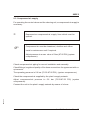
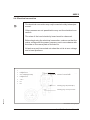
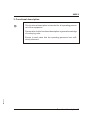
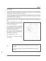
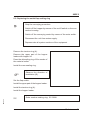
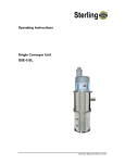
Operating Instructions
SM4-620
Conveyor Hopper
SSPE 5
Sterling Material Processing
Please note that our address and phone information has changed.
Please reference this page for updated contact information.
These manuals are obsolete and are provided only for their technical information, data and capacities.
Portions of these manuals detailing procedures or precautions in the operation, inspection, maintenance
and repair of the products may be inadequate, inaccurate, and/or incomplete and shouldn’t be relied
upon. Please contact the ACS Group for more current information about these manuals and their
warnings and precautions.
Parts and Service Department
The ACS Customer Service Group will provide your company with genuine OEM quality parts manufactured to engineering
design specifications, which will maximize your equipment’s performance and efficiency. To assist in expediting your phone
or fax order, please have the model and serial number of your unit when you contact us. A customer replacement parts list
is included in this manual for your convenience. ACS welcomes inquiries on all your parts needs and is dedicated to
providing excellent customer service.
For immediate assistance, please contact:
•
North, Central and South America, 8am – 5pm CST +1 (800) 483-3919 for drying, conveying, heating and cooling
and automation. For size reduction: +1 (800) 229-2919.
North America, emergencies after 5pm CST (847) 439-5855
North America email: [email protected]
•
Mexico, Central & South America
Email: [email protected]
•
Europe, Middle East & Africa +48 22 390 9720
Email: [email protected]
•
India +91 21 35329112
Email: [email protected]
•
Asia/Australia +86 512 8717 1919
Email: [email protected]
Sales and Contracting Department
Our products are sold by a worldwide network of independent sales representatives. Contact our Sales Department for the
name of the sales representative nearest you.
Let us install your system. The Contract Department offers any or all of these services: project planning; system packages
including drawings; equipment, labor, and construction materials; and union or non-union installations.
For assistance with your sales or system contracting needs please Call:
North, Central and South America +1 (262) 641-8600 or +1 (847) 273-7700 Monday–Friday, 8am–5pm CST
Europe/Middle East/Africa +48 22 390 9720
India +91 21 35329112
Asia/Australia +86 512 8717 1919
Facilities:
ACS offers facilities around the world to service you no matter where you are located. For more information, please visit us at
www.acscorporate.com
United States:
ACS Schaumburg – Corporate Offices
1100 E. Woodfield Road
Suite 588
Schaumburg, IL 60173
Phone: + 1 847 273 7700
Fax: + 1 847 273 7804
ACS New Berlin – Manufacturing Facility
th
2900 S. 160 Street
New Berlin, WI 53151
Phone : +1 262 641 8600
Fax: + 1 262 641 8653
Asia/Australia:
ACS Suzhou
109 Xingpu Road SIP
Suzhou, China 215126
Phone: + 86 8717 1919
Fax: +86 512 8717 1916
Europe/Middle East/Africa:
ACS Warsaw
Ul. Działkowa 115
02-234 Warszawa
Phone: + 48 22 390 9720
Fax: +48 22 390 9724
India
ACS India
Gat No. 191/1, Sandbhor Complex
Mhalunge, Chakan, Tal Khed,
Dist. Pune 410501, India
Phone: +91 21 35329112
Fax: + 91 20 40147576
SSPE 5
Sterling Material Processing
5200 West Clinton Ave
Milwaukee, WI 53223
Telephone: (414) 354-0970
Fax:(414) 354-6421
www.sterlco.com
Technical service:
Service department
Telephone: (800) 423-3183
Edition: 04/01
These operating instructions are for:*
(* Please fill in personally)
Serial number:
Built in:
Date of delivery:
Number of delivery:
Date of commissioning:
SM4-620
Location:
Group of machines:
2
SSPE 5
Sterling Material Processing retains all rights to change the information in these
operating instructions at any time without notice.
SM4-620
We assume no liability for any errors or direct or indirect damage resulting in context with these operating instructions.
Copying, translation or publication in any form except for personal use of purchaser requires approval from Sterling Material Processing.
All rights reserved.
3
SSPE 5
Table of contents
1. Safety instructions . . . . . . . . . . . . . . . . . . . . . . . . . . . . . . . . . . . . . . . . . . . . 6
1.1.
1.2.
1.3.
1.4.
Warnings and symbols . . . . . . . . . . . . . . . . . . . . . . . . . . . . . . . . . . 7
Explanations and information . . . . . . . . . . . . . . . . . . . . . . . . . . . . . 8
For your safety . . . . . . . . . . . . . . . . . . . . . . . . . . . . . . . . . . . . . . . . 9
For the safety of the equipment . . . . . . . . . . . . . . . . . . . . . . . . . . . 9
2. Installation instructions . . . . . . . . . . . . . . . . . . . . . . . . . . . . . . . . . . . . . . . 10
2.1.
2.2.
2.3.
2.4.
Transport . . . . . . . . . . . . . . . . . . . . . . . . . . . . . . . . . . . . . . . . . . . . 11
Set-up . . . . . . . . . . . . . . . . . . . . . . . . . . . . . . . . . . . . . . . . . . . . . . 12
Compressed-air supply . . . . . . . . . . . . . . . . . . . . . . . . . . . . . . . . . 13
Electrical connection . . . . . . . . . . . . . . . . . . . . . . . . . . . . . . . . . . . 14
3. Functional description . . . . . . . . . . . . . . . . . . . . . . . . . . . . . . . . . . . . . . . . 15
3.1. General . . . . . . . . . . . . . . . . . . . . . . . . . . . . . . . . . . . . . . . . . . . . . 16
3.2. Controller CSP . . . . . . . . . . . . . . . . . . . . . . . . . . . . . . . . . . . . . . . 17
4. Putting into operation . . . . . . . . . . . . . . . . . . . . . . . . . . . . . . . . . . . . . . . . 18
4.1. Setting the controller SSP . . . . . . . . . . . . . . . . . . . . . . . . . . . . . . 19
4.2. Alarm Messages displayed on the controller SSP . . . . . . . . . . . 20
5. Maintenance. . . . . . . . . . . . . . . . . . . . . . . . . . . . . . . . . . . . . . . . . . . . . . . . . 21
SM4-620
5.1. Maintenance intervals . . . . . . . . . . . . . . . . . . . . . . . . . . . . . . . . . . 23
5.2. Replacing the outlet flap sealing ring . . . . . . . . . . . . . . . . . . . . . . 24
5.2.1. Adjust the flap switch . . . . . . . . . . . . . . . . . . . . . . . . . . 25
5.3. Cleaning the hopper loader . . . . . . . . . . . . . . . . . . . . . . . . . . . . . 26
5.4. Cleaning/replacing the filter cartridges of the cleaning unit . . . . 27
4
SSPE 5
6. Technical data . . . . . . . . . . . . . . . . . . . . . . . . . . . . . . . . . . . . . . . . . . . . . . . 29
7. Spare parts list . . . . . . . . . . . . . . . . . . . . . . . . . . . . . . . . . . . . . . . . . . . . . . 31
8. Accessories . . . . . . . . . . . . . . . . . . . . . . . . . . . . . . . . . . . . . . . . . . . . . . . . . 34
o ________________________
o ________________________
o ________________________
SM4-620
o ________________________
5
SSPE 5
1. Safety instructions
»
These safety instructions apply to all persons within the range of
action of the equipment.
Please inform all persons within the range of action of the equipment of the direct and indirect hazards connected with the
equipment.
These operating instructions are to be used by all persons assigned activities connected with the equipment.
Knowledge of the English language is prerequisite.
Ensure in each case that the operating personnel are familiar
with the operating instructions and the function of the equipment.
SM4-620
Observe the safety instructions of the connected conveying
system.
Safety instructions 6
SSPE 5
1.1. Warnings and symbols
The following warnings and symbols are used in these operating instructions:
»
This symbol indicates danger to life! Fatal or serious injury is
possible if the corresponding instructions, regulations or warnings are not observed.
This symbol indicates that serious injury is possible if the corresponding instructions, regulations or warnings are not observed.
F
This symbol indicates that extensive damage to equipment
is possible if the corresponding instructions, regulations or
warnings are not observed.
&
This symbol indicates information important for becoming familiar with the equipment, i.e. technical correlations.
$
This symbol indicates that a technical term is explained at
this point.
SM4-620
L
Safety instructions 7
SSPE 5
1.2. Explanations and information
Various terms and designations are used frequently in these operating instructions to ensure clarity. Therefore please note that the terms used in the text stand
for the corresponding explanations listed below.
ment
· Equip
“Equipment” can mean an individual unit, a machine or an installation.
erating personnel
· Op
The “operating personnel” are persons operating the equipment on their own responsibility or according to instructions (minimum age: 16).
erator
· Op
The “operator” of the equipment (production manager, foreman, etc.) is the person responsible for all production sequences. The operator instructs the operating personnel of what is to be done.
erating instructions
· Op
The “plant operating instructions” describe the interaction of the equipment, production sequences or methods. The plant operating instructions must be compiled by the operator of the equipment.
ment foreman
· Equip
When several operating personnel work on one machine, the “equipment foreman” coordinates the sequences. The equipment foreman must be appointed by
the operator.
personnel
· Trained
“Trained personnel” are persons who, due to their training, are authorized to carry
SM4-620
out the required work in good practice.
Safety instructions 8
SSPE 5
1.3. For your safety
absolutely necessary that you observe the operating instructions for the cor· Itreisspond
ing conveying system.
device is intended exclusively for conveying plastic granules and regrind.
· The
Any other usage is not permitted.
· This device is not suitable for processing foods.
fore beginning maintenance work, set all compressed air piping on the device
· Be
at zero pressure. Danger of accidents!
device may only be operated if all corresponding components have been
· The
properly connected and are in accordance with the relevant regulations.
1.4. For the safety of the equipment
absolutely necessary that you observe the operating instructions for the cor· Itreisspond
ing conveying system.
· For the operation of the hoppers, a compressed-air supply is necessary.
set the operating pressure of the hoppers at more than 6 bar (87.02) PSI
· Never
(system overpressure).
stall the hoppers in such a way that the outlet flap is hinged in a right angle to the
· Indirec
tion of movement of the machine.
· Make sure that all plugs are connected properly.
SM4-620
· Observe the carrying capacity of the machine flange.
Safety instructions 9
SSPE 5
2. Installation instructions
»
These installation instructions are intended for persons with
skills in electrical and mechanical areas due to their training, experience and received instructions.
Personnel using these installation instructions must be instructed in the regulations for the prevention of accidents, the
operating conditions and safety regulations and their implementation.
Ensure in each case that the personnel are informed.
The installation instructions provided in the corresponding operating instructions apply for all connected equipment.
Observe safety regulations with regard to lifting gear handling
All installation work must be carried out with the equipment disconnected from electrical power and compressed air supply.
L
For installation work taking place at heights of over approx.
1829 mm. (6 ft.), use only ladders or similar equipment and
working platforms intended for this purpose. At greater
heights, the proper equipment for protection against falling
must be worn.
Use only suitable lifting gear which is in proper working order
and load suspension devices with sufficient carrying capacity. Do not stand or work under suspended loads!
SM4-620
Use suitable workshop equipment.
F
Installation instructions 10
SSPE 5
Install the equipment such that all parts are easily accessible; this facilitates maintenance and repair work.
2.1. Transport
For transport, only the appropriate lifting gear should be used (e.g. fork lift or
workshop crane).
Observe the safety instructions for the handling of lifting gear.
SM4-620
»
Observe the carrying capacity of the lifting gear.
Installation instructions 11
SSPE 5
2.2. Set-up
The arrangement of the hopper loaders may vary depending on the type of device to be conveyed on and the material used. Fastening onto fixed machine
throats is provided by means of strap retainers. However, additional support of
the hopper loader is necessary if the devices are not sufficiently capable of bearing the load.
Mount the hopper loader in such a way that the outlet flap swings in a right-hand
angle to the direction of machine movement. Please check during assembly that
the admissible bearing loads are not exceeded.
Please check that all connecting points are tight to ensure that the conveying performance is not impaired.
It should moreover be observed, particularly if custom produced connecting parts
are used, that the material discharged from the hopper loader must neither get
into the open nor must it clog the filter surfaces (observe angle of repose!).
F
Do not excessively load inlet nozzle of hopper loader,
remove hose separately, if necessary!
SM4-620
J
L
Assembly
Installation instructions 12
SSPE 5
2.3. Compressed-air supply
For operating the control valves and the cleaning unit, a compressed-air supply is
necessary.
L
Depressurize compressed-air supply lines which must be
opened.
F
Compressed air must be dewatered, dustfree and oilfree.
Install a maintenance unit if required.
Adjust pressure to a max. value of 6 bar (87.02 PSI) (system
overpressure).
Check compressed-air piping for correct installation and assembly.
Check fittings, length and quality of the hose connections for agreement with requirements.
The operating pressure is 5-6 bar (72.52-87.02 PSI) (system overpressure).
Check the compressed-air supplied by the plant’s supply network.
Adjust compressed-air pressure to 5-6 bar (72.52-87.02 PSI) (system
overpressure).
SM4-620
Connect the unit to the plant’s supply network by means of a hose.
Installation instructions 13
SSPE 5
2.4. Electrical connection
»
The electrical connection may only be carried out by trained personnel.
Other persons are not permitted to carry out the electrical connection.
The rules of the local electricity board must be observed.
Before beginning the electrical connection, make sure that the
mains voltage and the power frequency are in accordance with
the data on the name plate of the device.
All work may only be carried out when the unit is at zero voltage
and at zero pressure.
1
KL (= flap switch)
2
bridged with 4
connection point diaphragm valve (SV)
3
SV (= diaphragm valve)
connection controller SSP
4
bridged with 2
5
+ 24 V
6
0V
7
PE
connecting plug “flap switch (KL)”
SM4-620
connecting plug “conveyor control”
Connection housing hopper
Installation instructions 14
SSPE 5
3. Functional description
»
This functional description is intended for all operating personnel of the equipment.
Prerequisite for this functional description is general knowledge
of conveying units.
SM4-620
Ensure in each case that the operating personnel are sufficiently informed.
Functional description 15
SSPE 5
3.1. General
The conveyor hopper is used for the automatic conveyance of freely flowing plastic granules, regrind and powder. The hopper can only function in connection with
a single-station vacuum conveying system.
The conveyor hopper functions according to the principle of suction conveyance.
A high-performance turbine provides for the vacuum that is required to convey
the material into the separator.
In the separator the material is separated from air by several filter cartridges. After the conveying time is finished the turbine is switched off and the material emptied.
The automatic filter cleaning takes
place by adjustable compressed-air
shocks (pulse duration).
On the hopper, there is a separate
on/off switch (A) and a function controlling device which indicates the following operational modes:
B
A
C
D
(B): lamp on - hopper switched on at
the on/off switch (A); lamp flashes the hopper is conveying
(C): lamp flashes - error
(D): lamp is on - hopper signals lack
of material
Connection housing hopper
&
The filter-cleaning process takes place during the conveying
process.
SM4-620
The filter cartridges are cleaned in adjustable intervals (time
interval).
Functional description 16
SSPE 5
3.2. Controller CSP
The setting for the conveying time and the line clear time are made via the keys
(A1: “change-over” key, A2: “arrow key”) on the front of the control system. The
values which have been set will be displayed on the display (B). The values which
have been set are maintained after the machine has been shut off.
3 LEDs indicate the respective modes of operation: pulse duration (C), time interval (D), without function (E).
The pulse duration can be set to 0.5, 1.0 or 1.5 seconds.
&
The time interval can be set from 5 to 20 seconds.
When the unit is switched on all LEDs blink and the software
version is displayed.
C
B
D
E
SM4-620
A1
A2
Controller CSP
Functional description 17
SSPE 5
4. Putting into operation
»
This chapter is intended for operating personnel.
Prerequisite for this chapter is general knowledge of the operation of conveying units.
Also prerequisite for this chapter is that the functional description has been read and understood.
Ensure in each case that the operating personnel are sufficiently informed.
Make sure that the On/Off switch of the hopper loader connection housing is in position “1".
SM4-620
F
Observe the manual of the conveying system.
Putting into operation 18
SSPE 5
4.1. Setting the controller SSP
&
It is only possible to set the pulse duration / time interval
when the unit is not conveying any material.
Setting the pulse duration
Press the “arrow key”.
&
The pulse duration (= duration of a cleaning pulse) which
was last selected appears in the display.
0.5, 1.0 or 1.5 seconds may be set for the pulse duration.
Setting the time interval
Press the “arrow key” and
the “change-over” key.
&
The time interval which was last selected appears in the display.
SM4-620
5-20 seconds may be set for the time interval between 2
cleaning pulses.
Putting into operation 19
SSPE 5
4.2. Alarm Messages displayed on the controller SSP
If a disturbance occurs in the unit, an alarm message will be issued.
&
An “E” appears in the display and an error number.
“E2"
If the control system becomes too hot during operation (>70°C (158°F) the “E2"
alarm message is displayed and the unit is switched off.
Ensure that the control system is sufficient cooled.
The unit starts automatically after the cooling down phase.
SM4-620
&
Putting into operation 20
SSPE 5
5. Maintenance
»
This chapter is intended for persons with skills in electrical and
mechanical areas due to their training, experience and received
instructions.
Personnel using the instructions in this chapter must be instructed of the regulations for the prevention of accidents, the
operating conditions and safety regulations and their implementation.
Ensure in each case that the personnel are informed accordingly.
For maintenance work taking place at heights of over
approx.1829 mm (6 ft.), use only ladders or similar equipment
and working platforms intended for this purpose. At greater
heights, the proper equipment for protection against falling
must be worn.
Use only suitable lifting gear which is in proper working order
and load suspension devices with sufficient carrying capacity.
Do not stand or work under suspended loads!
Ensure that the electric motors/switch cabinets are sufficiently
protected against moisture.
Use only suitable workshop equipment.
Before starting maintenance work, appoint a supervisor.
Inform the responsible personnel before maintenance work on
the system is started.
Never operate the equipment when partially dismantled.
SM4-620
All maintenance and repair work not described in this chapter
may only be carried out by Sterling service personnel or authorized personnel (appointed by Sterling).
Maintenance 21
SSPE 5
L
Disconnect the equipment from mains supply before starting
maintenance procedures to ensure that it cannot be
switched on unintentionally.
Depressurize all compressed air piping of the equipment before starting maintenance work.
F
Please observe the maintenance intervals.
Before starting maintenance work, clean the equipment of
oil, fuel or lubricants.
Ensure that materials and incidentals required for operation
as well as spare parts are disposed of properly and in an environmentally sound manner.
Use only original Sterling spare parts.
SM4-620
Keep record of all maintenance and repair procedures.
Maintenance 22
SSPE 5
5.1. Maintenance intervals
Daily:
check warning signs on equipment for good
legibility and completeness.
Weekly:
check the maintenance unit
check the operating pressure in the factory
ductwork system (max. 6 bar (87.02 PSI) system
overpressure)
Monthly:
check the sealings on the filter cartridges
(according to the accumulation of dust)
Every six months:
check filter contamination, if necessary clean or
replace the filter cartridges
check all electrical and mechanical connections
for proper fit
check the settings of the level probes (if available)
check the sealing ring on the outlet flap
Yearly:
The given maintenance intervals are average values.
Check whether in your individual case the maintenance intervals must be shortened.
SM4-620
F
replace the sealing ring on the outlet flap
Maintenance 23
SSPE 5
5.2. Replacing the outlet flap sealing ring
»
Stop the conveying procedure.
Switch off the hopper by means of the on/off switch on the connection housing.
Switch off the conveying control by means of the main switch.
Disconnect the unit from mains supply.
Depressurize all system sections of the equipment.
Remove the tension ring (A).
Remove the upper part of the hopper
loader with hopper lid.
Draw the old sealing ring off the nozzle of
the material outlet.
Install the new sealing ring.
F
Observe the direction of
installation (B).
Set the flap switch.
Install the upper part of the hopper loader.
Install the tension ring (A).
SSPE 5
Install the hopper loader.
Order number sealing ring: ID 23098
SM4-620
&
Maintenance 24
SSPE 5
5.2.1. Adjust the flap switch
Remove the connecting plug “flap switch” from the connection housing of the
hopper.
Connect an ohmmeter to PINS 2 and 3 of the connecting plug “flap switch”.
Release the nuts (A) of the flap switch (B) until the support can be displaced.
Open the outlet flap (C) so far that
the front tip of the outlet flap is
approx. 30 mm ( 1.18 in) away from
the sealing surface.
Displace the flap switch (B) until
the contact of the magnet switch is
closed.
Tighten the nuts (A) of the flap
switch.
Check the adjustment:
In case of free hanging outlet flap
(empty hopper loader) the contact
of the magnet switch must be
closed.
C
B
A
Outlet flap
If the outlet flap cannot be properly adjusted, replace the flap switch or the outlet
flap with magnet.
Install the hopper.
&
Order numbers
SM4-620
flap switch:
ID 28839
outlet flap with magnet: ID 23093
Maintenance 25
SSPE 5
5.3. Cleaning the hopper loader
»
Stop the conveying procedure.
Switch off the hopper by means of the on/off switch on the connection housing.
Switch off the conveying control by means of the main switch.
Disconnect the unit from mains supply.
Depressurize all system sections of the equipment.
Open the tension ring (A).
Remove the hopper loader lid.
Remove the cleaning unit.
Open the tension ring (B).
Remove the upper part of the hopper
loader.
Clean the hopper loader by means of a
vacuum cleaner.
B
Install the upper part of the hopper loader.
Close the tension ring (B).
Mount the cleaning unit.
Mount the hopper loader lid.
Close the tension ring (A).
SSPE 5
SM4-620
Install the hopper.
Maintenance 26
SSPE 5
5.4. Cleaning/replacing the filter cartridges of the cleaning unit
»
Stop the conveying procedure.
Switch off the hopper by means of the on/off switch on the connection housing.
Switch off the conveying control by means of the main switch.
Disconnect the unit from mains supply.
Depressurize all system sections of the equipment.
F
Clean the separator hopper each time you are changing the
materials.
Use only cleaning agents which fulfil the corresponding requirements.
Only clean the separator hopper with compressed-air and/or
a brush.
The conveying capacity is diminished by a clogged filter cartridge.
SM4-620
&
Maintenance 27
SSPE 5
Removal
Open the tension ring (A).
Remove the hopper loader lid.
A
Remove the cleaning unit.
Release clamping devices of the filter cartridges.
Remove the filter cartridges from the intermediate platform.
Clean the filter cartridges from the inside
out by means of compressed air or replace the filter cartridges by new ones.
Installation
Insert filter cartridges into the opening of
the intermediate platform.
F
SSPE 5
Make sure that the sealing pad is tightly fitted between filter
cartridges and intermediate platform.
Mount clamping devices of the filter cartridges.
Mount the cleaning unit.
Mount the hopper loader lid.
Mount the tension ring.
Order number
filter cartridge, short version:
ID 83379
SM4-620
&
Maintenance 28
SSPE 5
6. Technical data
Basic Version
• Conveying hopper made of stainless steel
• Integrated high performance filter
• Automatic filter cleaning
• Integrated controller for cleaning
Performance
• Hopper loader capacity
SSPE 5: approx. 5 l (0.28 cf)
with extension module: max. 15 l (0.53 cf)
• Typical conveying capacity
SSPE 5: up to 250 kg/hr (550 lbs/hr)
with extension module: 400 kg/hr (880 lbs/hr)
Optional Features
• Extension module
SM4-620
Dimensions and data without obligation. Dimensions in mm (in.). Specifications may be subject to alterations.
Technical data 29
SSPE 5
Dimension Sheet
SM4-620
Dimensions and data without obligation. Dimensions in mm. (in.) Specifications may be subject to alterations.
Technical data 30
SSPE 5
7. Spare parts list
All other persons are not permitted to repair or to change the
equipment.
SM4-620
»
This parts list is only for the use of trained personnel only.
Spare parts list 31
SM4-620
SSPE 5
Spare parts list 32
SSPE 5
Order no.
Designation
1
26487
Pneumatic valve
2
85460
Vent valve
85462
Compressed-air container
97556
Solenoid valve
3
86851
Tension ring
4
98754
Sealing (1 m)
5
83081
Controller CSP (24 V)
6
83379
Filter cartridge, short version (4x)
7
85533
Tension ring
8
28420
Sealing
9
35796
Filter support
26299
Filter bag
10
85533
Tension ring
11
28420
Sealing
12
28839
Flap switch
26462
Cover
13
23098
Sealing ring
14
23093
Outlet flap with magnet
SM4-620
Pos.
Spare parts list 33
SSPE 5
8. Accessories
o ________________________
o ________________________
o ________________________
SM4-620
o ________________________
Accessories 34