1
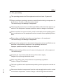
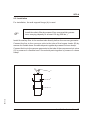
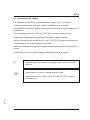
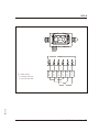
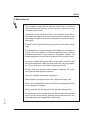
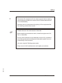
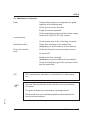
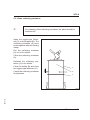
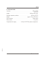
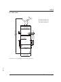
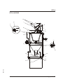
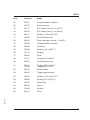
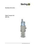
Operating Instructions
SM3-635a
Safety Filters
SFC-A 40
SFC-A 50
SFC-A 65
Sterling Material Processing
SFC-A
Sterling Material Processing
5200 West Clinton Ave.
Milwaukee, WI 53223
Telephone: (414) 354-0970
Fax: (414) 354-6421
www.sterlco.com
Parts and Service:
Telephone: (800) 423-3183
Edition: 12/98
These operating instructions are for:
*
Serial number:
Built in:
Date of delivery:
Number of delivery:
Date of commissioning:
SM3-635a
Location:
Group of machines:
* Please fill in personally
2
SFC-A
Sterling Material Processing retains all rights to change the information in these
operating instructions at any time without notice.
SM3-635a
We assume no liability for any errors or direct or indirect damage resulting in context with these operating instructions.
Copying, translation or publication in any form except for personal use of purchaser requires approval from Sterling Material Processing.
All rights reserved.
3
Please note that our address and phone information has changed.
Please reference this page for updated contact information.
These manuals are obsolete and are provided only for their technical information, data and capacities.
Portions of these manuals detailing procedures or precautions in the operation, inspection, maintenance
and repair of the products may be inadequate, inaccurate, and/or incomplete and shouldn’t be relied
upon. Please contact the ACS Group for more current information about these manuals and their
warnings and precautions.
Parts and Service Department
The ACS Customer Service Group will provide your company with genuine OEM quality parts manufactured to engineering
design specifications, which will maximize your equipment’s performance and efficiency. To assist in expediting your phone
or fax order, please have the model and serial number of your unit when you contact us. A customer replacement parts list
is included in this manual for your convenience. ACS welcomes inquiries on all your parts needs and is dedicated to
providing excellent customer service.
For immediate assistance, please contact:
•
North, Central and South America, 8am – 5pm CST +1 (800) 483-3919 for drying, conveying, heating and cooling
and automation. For size reduction: +1 (800) 229-2919.
North America, emergencies after 5pm CST (847) 439-5855
North America email: [email protected]
•
Mexico, Central & South America
Email: [email protected]
•
Europe, Middle East & Africa +48 22 390 9720
Email: [email protected]
•
India +91 21 35329112
Email: [email protected]
•
Asia/Australia +86 512 8717 1919
Email: [email protected]
Sales and Contracting Department
Our products are sold by a worldwide network of independent sales representatives. Contact our Sales Department for the
name of the sales representative nearest you.
Let us install your system. The Contract Department offers any or all of these services: project planning; system packages
including drawings; equipment, labor, and construction materials; and union or non-union installations.
For assistance with your sales or system contracting needs please Call:
North, Central and South America +1 (262) 641-8600 or +1 (847) 273-7700 Monday–Friday, 8am–5pm CST
Europe/Middle East/Africa +48 22 390 9720
India +91 21 35329112
Asia/Australia +86 512 8717 1919
Facilities:
ACS offers facilities around the world to service you no matter where you are located. For more information, please visit us at
www.acscorporate.com
United States:
ACS Schaumburg – Corporate Offices
1100 E. Woodfield Road
Suite 588
Schaumburg, IL 60173
Phone: + 1 847 273 7700
Fax: + 1 847 273 7804
ACS New Berlin – Manufacturing Facility
th
2900 S. 160 Street
New Berlin, WI 53151
Phone : +1 262 641 8600
Fax: + 1 262 641 8653
Asia/Australia:
ACS Suzhou
109 Xingpu Road SIP
Suzhou, China 215126
Phone: + 86 8717 1919
Fax: +86 512 8717 1916
Europe/Middle East/Africa:
ACS Warsaw
Ul. Działkowa 115
02-234 Warszawa
Phone: + 48 22 390 9720
Fax: +48 22 390 9724
India
ACS India
Gat No. 191/1, Sandbhor Complex
Mhalunge, Chakan, Tal Khed,
Dist. Pune 410501, India
Phone: +91 21 35329112
Fax: + 91 20 40147576
SFC-A
Table of contents
1. Safety instructions . . . . . . . . . . . . . . . . . . . . . . . . . . . . . . . . . . . . . . . . . . . . 6
1.1.
1.2.
1.3.
1.4.
Warnings and symbols . . . . . . . . . . . . . . . . . . . . . . . . . . . . . . . . . . 7
Explanations and information . . . . . . . . . . . . . . . . . . . . . . . . . . . . . 8
For your safety . . . . . . . . . . . . . . . . . . . . . . . . . . . . . . . . . . . . . . . . 9
For the operating safety of the equipment . . . . . . . . . . . . . . . . . . 12
2. Installation instructions . . . . . . . . . . . . . . . . . . . . . . . . . . . . . . . . . . . . . . . 14
2.1.
2.2.
2.3.
2.4.
Transport . . . . . . . . . . . . . . . . . . . . . . . . . . . . . . . . . . . . . . . . . . . . 16
Installation . . . . . . . . . . . . . . . . . . . . . . . . . . . . . . . . . . . . . . . . . . . 17
Compressed air supply . . . . . . . . . . . . . . . . . . . . . . . . . . . . . . . . . 18
Electrical connection . . . . . . . . . . . . . . . . . . . . . . . . . . . . . . . . . . . 19
3. Functioning description. . . . . . . . . . . . . . . . . . . . . . . . . . . . . . . . . . . . . . . 21
3.1. General . . . . . . . . . . . . . . . . . . . . . . . . . . . . . . . . . . . . . . . . . . . . . 22
4. Putting into operation . . . . . . . . . . . . . . . . . . . . . . . . . . . . . . . . . . . . . . . . 23
4.1. Checking the settings of the conveying control . . . . . . . . . . . . . . 24
4.2. Checking the line system . . . . . . . . . . . . . . . . . . . . . . . . . . . . . . . 24
5. Maintenance. . . . . . . . . . . . . . . . . . . . . . . . . . . . . . . . . . . . . . . . . . . . . . . . . 25
SM3-635a
5.1. Maintenance intervals . . . . . . . . . . . . . . . . . . . . . . . . . . . . . . . . . . 27
5.2. Clean collecting container . . . . . . . . . . . . . . . . . . . . . . . . . . . . . . 28
5.3. Clean/replace filter cartridge . . . . . . . . . . . . . . . . . . . . . . . . . . . . 29
4
SFC-A
6. Technical data . . . . . . . . . . . . . . . . . . . . . . . . . . . . . . . . . . . . . . . . . . . . . . . 31
6.1. Data sheet . . . . . . . . . . . . . . . . . . . . . . . . . . . . . . . . . . . . . . . . . . . 32
7. Appendix . . . . . . . . . . . . . . . . . . . . . . . . . . . . . . . . . . . . . . . . . . . . . . . . . . . 33
SM3-635a
7.1. Spare parts list . . . . . . . . . . . . . . . . . . . . . . . . . . . . . . . . . . . . . . . 34
5
SFC-A
1. Safety instructions
»
These safety instructions apply to all persons within the
range of action of the equipment.
Please inform all persons within the range of action of the
equipment of the direct and indirect hazards connected with
the equipment.
These operating instructions are to be used by all persons assigned activities connected with the equipment.
Knowledge of the English language is prerequisite.
SM3-635a
Ensure in each case that the operating personnel are familiar
with the operating instructions and the function of the equipment.
Safety instructions 6
SFC-A
1.1. Warnings and symbols
The following warnings and symbols are used in these operating instructions:
»
This symbol indicates danger to life! Fatal or serious injury is
possible if the corresponding instructions, regulations or
warnings are not observed.
This symbol indicates that serious injury is possible if the corresponding instructions, regulations or warnings are not observed.
F
This symbol indicates that extensive damage to equipment is
possible if the corresponding instructions, regulations or
warnings are not observed.
&
This symbol indicates information important for becoming familiar with the equipment, i.e. technical correlations.
$
This symbol indicates that a technical term is explained at this
point.
SM3-635a
L
Safety instructions 7
SFC-A
1.2. Explanations and information
Various terms and designations are used frequently in these operating instructions to ensure clarity. Therefore please note that the terms used in the text stand
for the corresponding explanations listed below.
ment
· Equip
“Equipment” can mean an individual unit, a machine or an installation.
erating personnel
· Op
The “operating personnel” are persons operating the equipment on their own responsibility or according to instructions (minimum age: 16).
erator
· Op
The “operator” of the equipment (production manager, foreman, etc.) is the person responsible for all production sequences. The operator instructs the operating personnel of what is to be done.
erating instructions
· Op
The “plant operating instructions” describe the interaction of the equipment, production sequences or methods. The plant operating instructions must be compiled by the operator of the equipment.
ment foreman
· Equip
When several operating personnel work on one machine, the “equipment foreman” coordinates the sequences. The equipment foreman must be appointed by
the operator.
personnel
· Trained
“Trained personnel” are persons who, due to their training, are authorized to carry
SM3-635a
out the required work in good practice.
Safety instructions 8
SFC-A
1.3. For your safety
· The operating personnel of this equipment must be at least 16 years old.
read these operating instructions carefully before taking into operation for
· Please
the first time. Contact us should questions arise.
This avoids injury and damage to equipment!
operating instructions must be kept available at all times at the place of op· These
eration of the equipment. Improper operation results in danger of accidents!
note that, for reasons of clarity, not all conceivable cases regarding opera· Please
tion or maintenance of the equipment can be covered in these operating instructions.
observe all safety instructions and warnings on the equipment.
· Please
This avoids injury and damage to equipment!
work on the equipment is to be carried out by persons whose qualifications are
· All
specified in the pertaining chapters of the operating instructions.
Improper operation results in danger of accidents!
proper working clothes are to be worn during any work on the equipment.
· The
This avoids injury!
pare the connected loads with those of the mains supply.
· Com
Danger of injury through electrical shock!
using lifting gear, please observe the pertaining regulations.
· When
Caution: Danger of accidents!
SM3-635a
local regulations and requirements pertaining to this equipment must be ob· The
served.
connect electrical components from the mains supply before work is carried
· Dis
out on these components. Caution: Danger to life through electrical shock!
Safety instructions 9
SFC-A
not modify, add other equipment or change the design of the equipment with· Do
out the approval of the manufacturer. Caution: Danger of accidents!
pile detailed operating instructions based on these Operating instructions for
· Com
the sequence of procedures to be carried out on this equipment.
Improper operation results in danger of accidents!
· Appoint an equipment foreman to be responsible for the equipment.
sure that the operating personnel are provided detailed instruction in the oper· En
ation of the equipment. Improper operation results in danger of accidents!
the main switch is switched off for reasons pertaining to safety, it must be
· When
secured against unauthorized activation. Caution: Danger of accidents!
· Before starting maintenance work, appoint a supervisor.
form the responsible personnel before maintenance work on the system is
· Instarted.
Caution: Danger of accidents!
connect the equipment from mains supply before starting maintenance proce· Dis
dures to ensure that it cannot be switched on unintentionally.
Caution: Danger of accidents!
pair work may be carried out by trained personnel only.
· Re
Caution: Danger of accidents!
operate the equipment when partially dismantled!
· Never
Danger! Limbs may be caught in machinery! Electric shock!
SM3-635a
of malfunction, shut down the equipment immediately. Have malfunctions
· Incorcase
rected immediately. Danger of accidents!
equipment is intended only for conveying granulated plastics and regrinds.
· The
Any other or additional use is contrary to specifications.
Safety instructions 10
SFC-A
· This equipment is not suitable for food processing.
note that sound levels exceeding 85 db(A) may in the long term damage
· Please
your health. Use the appropriate ear muffs. This avoids impairment of hearing!
tachments not supplied by Sterling must be manufactured in accordance with
· Atsafety
regulation EN 294. Danger of accidents!
pipes, hoses and screwed connections should be checked regularly for leaks
· All
and damage. Any faults which arise should be corrected immediately.
Danger of accidents!
pressurise all compressed air piping before starting maintenance work.
· De
Danger of accidents!
equipment may only be operated when all the associated components are
· The
properly connected up and in accordance with the relevant regulations.
· The equipment may only be used together with a conveying system.
SM3-635a
· The safety instructions of the connected machines must be followed.
Safety instructions 11
SFC-A
1.4. For the operating safety of the equipment
· Never change settings if the consequences are not precisely known.
· Use only original Sterling spare parts.
· Please observe the maintenance schedule.
· Keep record of all maintenance and repair work.
· Please note that electronic components may be damaged by static discharge.
all electrical connections for proper fit before the equipment is taken into
· Check
operation for the first time and at regular intervals.
· Never adjust sensors without exact knowledge of their function.
· Please note that the ambient temperature must not exceed 70 °C (158°F).
· The safety filter may only be used together with a conveying system.
safety filter requires a compressed-air supply (max. 5-6 bar (72-87 PSI) sys· The
tem overpressure).
set a higher operating pressure than 6 bar (87 PSI) for the safety filter (sys· Never
tem overpressure).
· Install the safety filter in the suction line right in front of the vacuum generator.
SM3-635a
serve that the filter cleaning procedure is carried out while the vacuum genera· Ob
tor is running.
· Observe the operating instructions of the conveying system.
Safety instructions 12
SFC-A
· Check the collecting container for tightness following each cleaning procedure.
· Make sure that the one-way restrictor regulation should not be changed.
· The operating instructions of the connected machines must be followed.
SM3-635a
· All components must be sufficiently grounded.
Safety instructions 13
SFC-A
2. Installation instructions
»
These installation instructions are intended for persons with
skills in electrical and mechanical areas due to their training,
experience and received instructions.
Personnel using these installation instructions must be instructed in the regulations for the prevention of accidents, the
operating conditions and safety regulations and their implementation.
Ensure in each case that the personnel are informed.
The installation instructions provided in the corresponding
operating instructions apply for all connected equipment.
Observe safety regulations with regard to lifting gear handling
All installation work must be carried out with the equipment
disconnected from electrical power and compressed air supply.
L
For installation work taking place at heights of over approx. 6
feet, use only ladders or similar equipment and working platforms intended for this purpose. At greater heights, the
proper equipment for protection against falling must be worn.
Use only suitable lifting gear which is in proper working order
and load suspension devices with sufficient carrying capacity. Do not stand or work under suspended loads!
SM3-635a
Use suitable workshop equipment.
Installation instructions 14
SFC-A
SM3-635a
F
Install the equipment such that all parts are easily accessible;
this facilitates maintenance and repair work.
Installation instructions 15
SFC-A
2.1. Transport
The unit is delivered as a complete sub-assembly. Transport the unit on a pallet.
Lift the unit only by the wall support flange (B) or by the separator container (A).
Use only suitable lifting gear (e.g. hoisting crane or forklift).
»
Observe the carrying capacity of the lifting gear.
Observe the safety instructions for the handling of lifting
gear.
F
Never lift the unit by the pneumatique valve.
C
A
C
SM3-635a
B
SFC-A
Installation instructions 16
SFC-A
2.2. Installation
For installation, the wall support flange (A) is used.
F
Install the safety filter by means of four screws which guarantee a carrying capacity of at least 100 kg (220 lbs.).
Install the safety filter in the suction tube directly before the vacuum generator.
Connect the line to the conveyor units to the tube of the hopper loader (B) by
means of a flexible hose. Screw both parts together by means of a hose clamp.
Connect the line to the vacuum generator to the tube of the compressed-air valve
(C) by means of a flexible hose. Screw both parts together by means of a hose
clamp.
C
B
SM3-635a
A
SFC-A
Installation instructions 17
SFC-A
2.3. Compressed air supply
For operation of the valve, a compressed-air supply (1/4 “) is needed.
Check compressed air piping for correct installation and assembly.
Check fittings, length and quality of the hose connections for agreement with requirements.
The operating pressure is 5-6 bar (72-87 PSI) (system overpressure).
Check the compressed air supplied by the plant’s supply network.
Adjust compressed air pressure to 5-6 bar (72-87 PSI) (system overpressure).
Compressed air must be dewatered and oiled.
Install a maintenance unit (pressure reducer with water separator and oiler) if required.
Connect the unit to the plant’s supply network by means of a hose.
L
Depressurize compressed air supply lines which must be
opened.
F
Compressed air must be dewatered and oiled.
SM3-635a
Adjust pressure to a max. value of 6 bar (87 PSI) (system
overpressure).
Installation instructions 18
SFC-A
2.4. Electrical connection
»
The electrical connection may only be carried out by trained
personnel.
The regulations of the local Electricity Board must be observed.
All work must be carried out with the unit disconnected from
voltage and pressure supply.
It is not permitted for other persons to undertake the electrical
connection.
F
Observe the electrical manual of the conveying system.
SM3-635a
Put the plug into the socket of the safety filter and secure it with the holding clamp.
Installation instructions 19
SFC-A
Han 6
1
2
3
4
5
6
1
2
3
4
5
6
S1 = Safety switch
AV = Cleaning valve, top
VV = Vacuum valve, side
S1
AV
VV
SM3-635a
Connection housing
Installation instructions 20
SFC-A
3. Functioning description
»
This functioning description is intended for all operating personnel of the equipment.
Prerequisite for this functioning description is general knowledge of conveying systems.
Ensure in each case that the operating personnel are sufficiently informed.
The safety filter may only be used together with a conveying
system.
SM3-635a
&
Functioning description 21
SFC-A
3.1. General
The safety filter is used to clean the vacuum air of the entire system and must be
installed in every multi-location suction conveyor system .
A filter cartridge inside the safety filter separates the vacuum air from the dust
particles flowing along with it. Vacuum pressure is built up in the safety filter following a filter monitoring period. Surrounding air is conducted into the safety filter
by means of a valve. The direction of flow is opposite to the normal direction of
flow. The dust is blown through the filter cartridge and collected in a receptacle.
No materials are conveyed during the cleaning procedure. The cycle, during
which the filter cartridge is cleaned, is adjustable. Observe the operating instructions of the conveyor system.
&
The filter cleaning procedure is carried out while the vacuum
generator is running.
The collecting container can be opened by hand for cleaning. The correct seating
of the collecting container is monitored by a safety switch.
The number and way of the setting depends on the connected conveying control.
The filter cannot be cleaned unless the collecting container is
correctly inserted.
SM3-635a
&
Functioning description 22
SFC-A
4. Putting into operation
»
This chapter is intended for operating personnel.
Prerequisite for this chapter is general knowledge of the operation of conveying systems.
Also prerequisite for this chapter is that the functioning description has been read and understood.
Ensure in each case that the operating personnel are sufficiently informed.
F
Check the compressed-air supply (max. 5-6 bar (72-87 PSI)
system overpressure).
Check the connections of the lines (conveying lines and vacuum lines).
Check to make sure the collecting container is correctly inserted.
Check the electrical connection.
The safety filter can only be used together with a conveying
system.
SM3-635a
&
Putting into operation 23
SFC-A
4.1. Checking the settings of the conveying control
The number and way of the setting depends on the connected conveying control.
This is a description of two possibilities.
Surveillance time
This is safety filter monitoring time between two cleanings. Has this time passed,
the safety filter ist cleaned automatically.
Cleaning cycles
Number of cleaning pulses during a cleaning process.
4.2. Checking the line system
Remove the flexible line from the connected material receptacle.
Start a conveying procedure.
Use your hand to cover the open end of the line.
As the vacuum generator runs up, you must feel the suction with your hand within
a few seconds.
If no vacuum pressure is felt, the system of lines is leaking.
Check the system of lines and seal off the leak.
Start the conveying procedure.
SM3-635a
Connect the conveyor line again.
Putting into operation 24
SFC-A
5. Maintenance
»
This chapter is intended for persons with skills in electrical
and mechanical areas due to their training, experience and
received instructions.
Personnel using the instructions in this chapter must be instructed of the regulations for the prevention of accidents, the
operating conditions and safety regulations and their implementation.
Ensure in each case that the personnel are informed accordingly.
For maintenance work taking place at heights of over approx.
6 feet, use only ladders or similar equipment and working
platforms intended for this purpose. At greater heights, the
proper equipment for protection against falling must be worn.
Use only suitable lifting gear which is in proper working order
and load suspension devices with sufficient carrying capacity. Do not stand or work under suspended loads!
Ensure that the electric motors/switch cabinets are sufficiently protected against moisture.
Use only suitable workshop equipment.
Before starting maintenance work, appoint a supervisor.
Inform the responsible personnel before maintenance work
on the system is started.
Never operate the equipment when partially dismantled.
SM3-635a
All maintenance and repair work not described in this chapter
may only be carried out by Sterling service personnel or authorized personnel (appointed by Sterling).
Maintenance 25
SFC-A
L
Disconnect the equipment from mains supply before starting
maintenance procedures to ensure that it cannot be switched
on unintentionally.
Depressurize all compressed air piping of the equipment before starting maintenance work.
F
Please observe the maintenance intervals.
Before starting maintenance work, clean the equipment of oil,
fuel or lubricants.
Ensure that materials and incidentals required for operation
as well as spare parts are disposed of properly and in an environmentally sound manner.
Use only original Sterling spare parts.
SM3-635a
Keep record of all maintenance and repair procedures.
Maintenance 26
SFC-A
5.1. Maintenance intervals
Daily:
Check warning signs on equipment for good
legibility and completeness.
Check the oil level in the oiler.
Empty the water separator.
Check operating pressure of the plant’s supply
network (5-6 bar (72-87 PSI) system
overpressure).
Check waste level in the collecting container.
Weekly/monthly:
Clean filter cartridge in the safety filter
(depending on accumulation of dust earlier!).
Every six months:
tions
Check all electrical and mechanical connecfor secure fit.
Replace the filter cartridge
(depending on accumulation of dust earlier!).
Check the sealing rings of the nonreturn valve
and the outlet flap.
&
This maintenance schedule is calculated for 3-shift operation.
F
Only the Sterling service should put the one-way restrictor
into action.
The given maintenance intervals are average values.
SM3-635a
Check whether in your individual case the maintenance intervals must be shortened.
Maintenance 27
SFC-A
5.2. Clean collecting container
L
For cleaning of the collecting container, the plant should be
switched off.
Open the toggle-type fasteners (C) on the support (B). The
collecting container (A) turns
down together with the holding
clamp.
Pull the collecting container
(A) out of the holder.
Clean the collecting container
(A).
Reinstall the collecting container (A) in the holder.
Close the holder (B) and close
the toggle-type fasteners (C).
Check the collecting container
for tightness.
C
B
A
SM3-635a
SFC-A
Maintenance 28
SFC-A
5.3. Clean/replace filter cartridge
»
Stop the conveying procedure.
Switch off the conveying system at the main switch.
Interrupt the mains supply.
Set all compressed-air lines at zero pressure.
&
Clogged filter cartridges reduce conveyor performance.
Loosen the tightening strap (B) between the separator lid (A) and separator container (C).
Remove the separator lid (A) from the
separator container (C).
Pull the filter cartridge out of the separator container (C).
Use compressed air to blow through
the filter cartridge from the inside to the
outside or replace the filter cartridge.
A
B
C
SM3-635a
SFC-A
Maintenance 29
SFC-A
Install the filter cartridge in the separator container (C).
Install the separator lid (A) on the separator container (C).
Mount the tightening strap (B) between the separator lid (A) and the separator
container (C).
&
Order number
ID 86348
SM3-635a
filter cartridge:
Maintenance 30
SFC-A
6. Technical data
Versions: . . . . . . . . . . . . . . . . . . . . . . . . . . . . . . . . . . . . . . . . . . . . SFC-A 40/50
. . . . . . . . . . . . . . . . . . . . . . . . . . . . . . . . . . . . . . . . . . . . . . . . . . . . . . . SFC-A 65
Height: . . . . . . . . . . . . . . . . . . . . . . . . . . . . . . . . . . . . . . . . 1500 mm (56") max.
Diameter separator container: . . . . . . . . . . . . . . . . . . . . . . . . 400 mm (15.75")
Weight: . . . . . . . . . . . . . . . . . . . . . . . . . . . . . . . . . . . approx. 53 kg (123.5 lbs.)
Filter cartridge: . . . . . . . . . . . . . . . . . . . . . . . . . . . . . . . . . . . . . . . . paper fleece
Filter surface: . . . . . . . . . . . . . . . . . . . . . . . . . . . . . . . . . . . . . . . . . . 1.6 m (63")
2
SM3-635a
Compressed air supply: . . . . . . . . . 4-6 bar (72-87 PSI) system overpressure
Technical data 31
SFC-A
6.1. Data sheet
A
A
SFC-A 40: 40 mm; 1,6"
SFC-A 50: 50 mm; 2,0"
SFC-A 65: 65 mm; 2,5 “
12 mm
0.47"
16O mm
6.3"
15O0 mm
59"
A
4OO mm
15.75"
47O mm
18.5"
41O mm
16.15"
SM3-635a
Dimensions in mm. Specifications may be subject to alterations.
Technical data 32
SFC-A
SM3-635a
7. Appendix
Appendix 33
SFC-A
7.1. Spare parts list
»
This spare parts list is intended to be used only by trained personnel.
SM3-635a
Other persons are not permitted to modify or repair the equipment.
Appendix 34
SFC-A
SFC-A 40/50/65
80
61
1
17
86
12
85
35
3
37
14
20
48
49
21
51
34
55
68
16
60
69
SM3-635a
32
Appendix 35
SFC-A
Pos.
Orderno.
Name
01
93551
Compressed-air cylinder
03
96372
Solenoid valve
12
98177
PVC fabric hose (0.7 m)(27.6")
14
98706
PVC fabric hose (1.0 m)(39.4")
16
95417
Sealing (1.35 m)(53.15")
17
93569
Profile tension ring
20
86348
Filter cartridge, conical 1.6 m (63")
21
27086
Compressed-air cylinder
32
09042
Container
34
99839
Sealing (1.4 m)(55.1")
35
15110
Sealing
37
09046
Filter
48
17011
Connection housing
49
99876
Profile tension ring
51
85610
17989
Sealing SFC-A 40/65
Sealing SFC-A 65
55
93570
Safety switch
60
96480
Toggle-type fastener
61
95881
Sealing (1.35 m)(53.15")
68
99880
Sealing (0.6 m)(23.6")
69
00159
Outlet flap
80
86640
Valve
85
13020
Sealing
86
88141
Valve
SM3-635a
2
Appendix 36