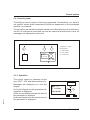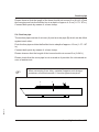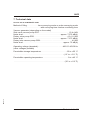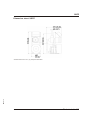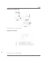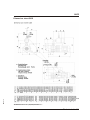
1
Operating Instructions
SM4-618
Conveyor Hopper
with blower-filter unit SGFE
Sterling Material Processing
Please note that our address and phone information has changed.
Please reference this page for updated contact information.
These manuals are obsolete and are provided only for their technical information, data and capacities.
Portions of these manuals detailing procedures or precautions in the operation, inspection, maintenance
and repair of the products may be inadequate, inaccurate, and/or incomplete and shouldn’t be relied
upon. Please contact the ACS Group for more current information about these manuals and their
warnings and precautions.
Parts and Service Department
The ACS Customer Service Group will provide your company with genuine OEM quality parts manufactured to engineering
design specifications, which will maximize your equipment’s performance and efficiency. To assist in expediting your phone
or fax order, please have the model and serial number of your unit when you contact us. A customer replacement parts list
is included in this manual for your convenience. ACS welcomes inquiries on all your parts needs and is dedicated to
providing excellent customer service.
For immediate assistance, please contact:
•
North, Central and South America, 8am – 5pm CST +1 (800) 483-3919 for drying, conveying, heating and cooling
and automation. For size reduction: +1 (800) 229-2919.
North America, emergencies after 5pm CST (847) 439-5855
North America email: [email protected]
•
Mexico, Central & South America
Email: [email protected]
•
Europe, Middle East & Africa +48 22 390 9720
Email: [email protected]
•
India +91 21 35329112
Email: [email protected]
•
Asia/Australia +86 512 8717 1919
Email: [email protected]
Sales and Contracting Department
Our products are sold by a worldwide network of independent sales representatives. Contact our Sales Department for the
name of the sales representative nearest you.
Let us install your system. The Contract Department offers any or all of these services: project planning; system packages
including drawings; equipment, labor, and construction materials; and union or non-union installations.
For assistance with your sales or system contracting needs please Call:
North, Central and South America +1 (262) 641-8600 or +1 (847) 273-7700 Monday–Friday, 8am–5pm CST
Europe/Middle East/Africa +48 22 390 9720
India +91 21 35329112
Asia/Australia +86 512 8717 1919
Facilities:
ACS offers facilities around the world to service you no matter where you are located. For more information, please visit us at
www.acscorporate.com
United States:
ACS Schaumburg – Corporate Offices
1100 E. Woodfield Road
Suite 588
Schaumburg, IL 60173
Phone: + 1 847 273 7700
Fax: + 1 847 273 7804
ACS New Berlin – Manufacturing Facility
th
2900 S. 160 Street
New Berlin, WI 53151
Phone : +1 262 641 8600
Fax: + 1 262 641 8653
Asia/Australia:
ACS Suzhou
109 Xingpu Road SIP
Suzhou, China 215126
Phone: + 86 8717 1919
Fax: +86 512 8717 1916
Europe/Middle East/Africa:
ACS Warsaw
Ul. Działkowa 115
02-234 Warszawa
Phone: + 48 22 390 9720
Fax: +48 22 390 9724
India
ACS India
Gat No. 191/1, Sandbhor Complex
Mhalunge, Chakan, Tal Khed,
Dist. Pune 410501, India
Phone: +91 21 35329112
Fax: + 91 20 40147576
SGFE
Sterling Material Processing
5200 West Clinton Ave.
Milwaukee, WI 53223
Telephone: (414) 354-0970
Fax: (414) 354-6421
www.sterlco.com
Technical service:
Service department
Telephone: (800) 423-3183
Edition: 10/01
These operating instructions are for:*
(* Please fill in personally)
Serial number:
Built in:
Date of delivery:
Number of delivery:
Date of commissioning:
SM4-618
Location:
Group of machines:
2
SGFE
Sterling Material Processing retains all rights to change the information in these
operating instructions at any time without notice.
SM4-618
We assume no liability for any errors or direct or indirect damage resulting in context with these operating instructions.
Copying, translation or publication in any form except for personal use of purchaser requires approval from Sterling Material Processing.
All rights reserved.
3
SGFE
Table of contents
1. Safety instructions . . . . . . . . . . . . . . . . . . . . . . . . . . . . . . . . . . . . . . . . . . 1-1
1.1. General. . . . . . . . . . . . . . . . . . . . . . . . . . . . . . . . . . . . . . . . . . . . . 1-1
1.2. For your safety . . . . . . . . . . . . . . . . . . . . . . . . . . . . . . . . . . . . . . . 1-2
1.3. For the operating safety of the equipment . . . . . . . . . . . . . . . . . 1-5
2. Concerning these Operating Instructions . . . . . . . . . . . . . . . . . . . . . . . 2-1
2.1.
2.2.
2.3.
2.4.
General Information . . . . . . . . . . . . . . . . . . . . . . . . . . . . . . . . . . . 2-1
Warning Messages and Symbols . . . . . . . . . . . . . . . . . . . . . . . . 2-2
Explanations and Definitions . . . . . . . . . . . . . . . . . . . . . . . . . . . . 2-3
Notes on Usage . . . . . . . . . . . . . . . . . . . . . . . . . . . . . . . . . . . . . . 2-4
3. Start-up . . . . . . . . . . . . . . . . . . . . . . . . . . . . . . . . . . . . . . . . . . . . . . . . . . . . 3-1
3.1. General. . . . . . . . . . . . . . . . . . . . . . . . . . . . . . . . . . . . . . . . . . . . . 3-1
3.2. Control system . . . . . . . . . . . . . . . . . . . . . . . . . . . . . . . . . . . . . . . 3-2
3.2.1. Operation . . . . . . . . . . . . . . . . . . . . . . . . . . . . . . . . . . . 3-2
3.2.2. Key assignment . . . . . . . . . . . . . . . . . . . . . . . . . . . . . . 3-3
3.3. Switching on the control system . . . . . . . . . . . . . . . . . . . . . . . . . 3-3
3.4. Setting the basic parameters . . . . . . . . . . . . . . . . . . . . . . . . . . . 3-4
3.5. Starting the conveying procedure . . . . . . . . . . . . . . . . . . . . . . . . 3-7
3.6. The first conveying operations . . . . . . . . . . . . . . . . . . . . . . . . . . 3-7
3.7. Viewing Alarm Messages . . . . . . . . . . . . . . . . . . . . . . . . . . . . . . 3-8
3.8. Switching off the unit . . . . . . . . . . . . . . . . . . . . . . . . . . . . . . . . . . 3-9
SM4-618
4. Maintenance . . . . . . . . . . . . . . . . . . . . . . . . . . . . . . . . . . . . . . . . . . . . . . . . 4-1
4.1.
4.2.
4.3.
4.4.
4.5.
4.6.
4.7.
General. . . . . . . . . . . . . . . . . . . . . . . . . . . . . . . . . . . . . . . . . . . . . 4-1
Maintenance schedule. . . . . . . . . . . . . . . . . . . . . . . . . . . . . . . . . 4-3
Checking the direction of rotation of the vacuum generator . . . 4-5
Testing the conduit system . . . . . . . . . . . . . . . . . . . . . . . . . . . . . 4-6
Adjusting the suction tube . . . . . . . . . . . . . . . . . . . . . . . . . . . . . . 4-7
Cleaning/replacing the filter cartridge . . . . . . . . . . . . . . . . . . . . . 4-8
Servicing the accessories . . . . . . . . . . . . . . . . . . . . . . . . . . . . . . 4-9
4
SGFE
5. Assembly instructions . . . . . . . . . . . . . . . . . . . . . . . . . . . . . . . . . . . . . . . 5-1
5.1.
5.2.
5.3.
5.4.
5.5.
5.6.
Transport . . . . . . . . . . . . . . . . . . . . . . . . . . . . . . . . . . . . . . . . . . . 5-2
Installation . . . . . . . . . . . . . . . . . . . . . . . . . . . . . . . . . . . . . . . . . . 5-2
Material feed . . . . . . . . . . . . . . . . . . . . . . . . . . . . . . . . . . . . . . . . 5-2
Suction pipe . . . . . . . . . . . . . . . . . . . . . . . . . . . . . . . . . . . . . . . . . 5-3
Pipework. . . . . . . . . . . . . . . . . . . . . . . . . . . . . . . . . . . . . . . . . . . . 5-4
Vacuum generator . . . . . . . . . . . . . . . . . . . . . . . . . . . . . . . . . . . . 5-5
5.6.1. Rotary lobe vacuum pump GDK . . . . . . . . . . . . . . . . . 5-6
5.7. Installing the accessories . . . . . . . . . . . . . . . . . . . . . . . . . . . . . . 5-6
5.8. Electrical connection . . . . . . . . . . . . . . . . . . . . . . . . . . . . . . . . . . 5-7
6. Functional description . . . . . . . . . . . . . . . . . . . . . . . . . . . . . . . . . . . . . . . 6-1
6.1. General. . . . . . . . . . . . . . . . . . . . . . . . . . . . . . . . . . . . . . . . . . . . . 6-1
7. Technical data . . . . . . . . . . . . . . . . . . . . . . . . . . . . . . . . . . . . . . . . . . . . . . 7-1
8. Spare parts list. . . . . . . . . . . . . . . . . . . . . . . . . . . . . . . . . . . . . . . . . . . . . . 8-1
9. Accessories . . . . . . . . . . . . . . . . . . . . . . . . . . . . . . . . . . . . . . . . . . . . . . . . 9-1
o conveyor hopper SSE 15 / SSE 30
o conveyor hopper _ _ _ _ _ _ _ _ _ _ _ _ _ _ _ _ _ _ _ _ _ _ _ _ _
o side vane vacuum pump GSV
o rotary value pump GDS
o rotary lobe vacuum pump GDK
o ____________________________________
SM4-618
10. Electrical manual . . . . . . . . . . . . . . . . . . . . . . . . . . . . . . . . . . . . . . . . . . 10-1
o Connection diagram no.: _ _ _ _ _ _ _ _ _ _ _ _ _ _ _ _ _ _
o Currently not available; will be delivered at a later date!
5
General
1. Safety instructions
1.1. General
»
These safety instructions apply to all persons within the range of
action of the equipment.
Please inform all persons within the range of action of the equipment of the direct and indirect hazards connected with the
equipment.
These operating instructions are to be used by all persons assigned activities connected with the equipment.
Knowledge of the English language is prerequisite.
SM4-618
Ensure in each case that the operating personnel are familiar
with the operating instructions and the function of the equipment.
Safety instructions 1-1
For your safety
1.2. For your safety
General
The operating personnel of this equipment must be at least 16 years old.
Please read these operating instructions carefully before taking into operation for
the first time. Contact us should questions arise. This avoids injury and damage
to equipment!
These operating instructions must be kept available at all times at the place of
operation of the equipment. Improper operation results in danger of accidents!
Please note that, for reasons of clarity, not all conceivable cases regarding operation or maintenance of the equipment can be covered in these operating instructions.
Please observe all safety instructions and warnings on the equipment. This
avoids injury and damage to equipment!
All work on the equipment is to be carried out by persons whose qualifications are
specified in the pertaining chapters of the operating instructions. Improper operation results in danger of accidents!
The proper working clothes are to be worn during any work on the equipment.
This avoids injury!
The local regulations and requirements pertaining to this equipment must be observed.
Disconnect electrical components from the mains supply before work is carried
out on these components Caution: Danger to life through electrical shock!
Compile detailed operating instructions based on these Operating instructions
for the sequence of procedures to be carried out on this equipment. Improper
operation results in danger of accidents!
SM4-618
Please note that sound levels exceeding 85 db(A) may in the long term damage
your health. Use the appropriate ear muffs. This avoids impairment of hearing!
Safety instructions 1-2
For your safety
Assembly
Compare the connected loads with those of the mains supply. Danger of injury
through electrical shock!
When using lifting gear, please observe the pertaining regulations. Caution: Danger of accidents!
Do not modify, add other equipment or change the design of the equipment without the approval of the manufacturer. Caution: Danger of accidents!
Attachments not supplied by Sterling must be manufactured in accordance with
safety regulation EN 294. Danger of accidents!
The equipment may only be operated when all the associated components are
properly connected up and in accordance with the relevant regulations. This
avoids injury and damage to equipment!
Operate the device only if all its components are grounded. Danger: accident
through electrical shock!
Solid particles and dust must be separated before entry to the vacuum generator.
This avoids damage to equipment!
If PVC hoses are used for conveying, they must be grounded. This avoids injury
and damage to equipment!
SM4-618
An acoustic cover should be installed when vacuum generators are located in
work rooms. This avoids impairment of hearing!
Safety instructions 1-3
For your safety
Operation
Appoint an equipment foreman to be responsible for the equipment.
Ensure that the operating personnel are provided detailed instruction in the operation of the equipment. Improper operation results in danger of accidents!
When the main switch is switched off for reasons pertaining to safety, it must be
secured against unauthorized activation. Caution: Danger of accidents!
Repair work may be carried out by trained personnel only.
Caution: Danger of accidents!
Never operate the equipment when partially dismantled!
Danger! Limbs may be caught in machinery! Electric shock!
In case of malfunction, shut down the equipment immediately. Have malfunctions
corrected immediately. Danger of accidents!
The equipment is intended only for conveying granulated plastics and regrinds.
Any other or additional use is contrary to specifications.
This equipment is not suitable for food processing.
The safety instructions of the connected machines must be followed.
Explosive gases and mixtures of gas and air must not be conveyed. Danger of explosion! Avoids injury or damage to equipment!
Maintenance
Before starting maintenance work, appoint a supervisor.
Inform the responsible personnel before maintenance work on the system is
started. Caution: Danger of accidents!
Disconnect the equipment from mains supply before starting maintenance procedures to ensure that it cannot be switched on unintentionally.
Caution: Danger of accidents!
SM4-618
All pipes, hoses and screwed connections should be checked regularly for leaks
and damage. Any faults which arise should be corrected immediately.
Danger of accidents!
Depressurise all compressed air piping before starting maintenance work.
Danger of accidents!
Safety instructions 1-4
For the operating safety of the equipment
1.3. For the operating safety of the equipment
Never change settings if the consequences are not precisely known.
Use only original Sterling spare parts.
Please observe the maintenance schedule.
Keep record of all maintenance and repair work.
Please note that electronic components may be damaged by static discharge.
Check all electrical connections for proper fit before the equipment is taken into
operation for the first time and at regular intervals.
Please ensure that the permitted operation temperature lies between 0 °C and
+45 °C (32°F and 113°F).
Please ensure that the permitted storage temperature lies between -25 °C and
+55 °C (-13°F and 131°F).
Note down all setting data.
After connection to the electricity supply has been made, check the rotational direction of the vacuum generators (note the direction indicated by the arrow).
Please ensure that all plugs are correctly plugged in.
The operating instructions of the connected machines must be followed.
All components must be sufficiently grounded.
Please note that a compressed air supply is required for the operation of the unit.
Never set a higher operating pressure than 6 bar (87.02 PSI) for the unit (system
overpressure).
Align the suction tubes correctly.
SM4-618
Please note that the maximum permitted ambient and air temperature on entry to
the vacuum generator is 40 °C (104°F).
Safety instructions 1-5
General Information
2. Concerning these Operating Instructions
2.1. General Information
»
These operating instructions are addressed to all users of the
device.
SM4-618
These operating instructions must be used by every person
charged with work on the unit.
Concerning these Operating Instructions 2-1
Warning Messages and Symbols
2.2. Warning Messages and Symbols
The following warning messages and symbols are used in these operating instructions:
»
This symbol indicates danger to life! Fatal or serious injury is
possible if the corresponding instructions, regulations or warnings are not observed.
This symbol indicates that serious injury is possible if the corresponding instructions, regulations or warnings are not observed.
F
This symbol indicates that extensive damage to equipment
is possible if the corresponding instructions, regulations or
warnings are not observed.
&
This symbol indicates information important for becoming familiar with the equipment, i.e. technical correlations.
$
This symbol indicates that a technical term is explained at
this point.
SM4-618
L
Concerning these Operating Instructions 2-2
Explanations and Definitions
2.3. Explanations and Definitions
In this operating manual, certain terms are used repeatedly for better clarity.
Therefore please keep in mind that these terms stand for the explanations given
here.
· Unit
“Unit” may designate either a single device, a machine or a plant.
· User
The user is the person who uses the unit on his or her own responsibility or on the
responsibility of someone else.
rator
· Ope
The operator of a unit (production manager, foreman etc.) is the person responsible for the sum of the processes. The operator instructs the users to do something.
rating manual
· Ope
The operating manual describes the correlations between several units, processes or manufacturing procedures. The operating manual must be prepared by
the operator of the units.
· Co-ordinator
If several users work on one unit, the “co-ordinator” co-ordinates the processes.
The co-ordinator must be designated by the operator.
ned personnel
· Trai
Trained personnel are people who are qualified by their training to carry out the
SM4-618
respective work in a professional manner.
Concerning these Operating Instructions 2-3
Notes on Usage
2.4. Notes on Usage
perienced operators can begin directly with the chapter on “Start-up” if the unit
· Ex
has been properly installed.
SM4-618
not been installed yet, observe the instructions in the chapter on
· If“Asthesemunitblyhas
Instructions”.
Concerning these Operating Instructions 2-4
General
3. Start-up
3.1. General
»
This chapter is directed at the operator of the equipment.
This chapter assumes general skills in dealing with conveying
units and SPS control units.
This chapter assumes that the functional description has been
read and understood.
It should be ensured in each and every case that the operators
have the relevant skills.
Explosive gases and mixtures of gas and air must not be conveyed by the vacuum generator. Solid particles and dust must
be separated before entry to the vacuum generator.
F
Check the compressed air supply if pneumatic valves are
present (5-6 bar (72.52-87.02 PSI) system overpressure).
Check whether the plastic stoppers have been removed from
the suction pipe of the vacuum generator.
SM4-618
Check that the on/off switch is in position ”OFF".
Start-up 3-1
Control system
3.2. Control system
The facility’s control system is factory-programmed. Nevertheless, you have to
set specific values (basic parameters) which are dependent on the processed
material, for instance.
The set values are saved and remain saved even after switching off or after a power fail. All entries are saved and can also be viewed at a later point in time. All
messages are displayed in plain text.
D
A
A=Lamp“ope
B
ration”
B=Lamp“alarm”
C = Main switch
C
D = Key “Reset”
I: 1 2 3 4 5 6
Mo 08:33
E = Control unit
Q: 1 2 3 4 RUN
ESC
OK
E
Switchbox
3.2.1. Operation
The control system is operated via the
keys “ESC”, “OK” and the arrow keys (A).
SM4-618
Messages are displayed on a four-line
display.
In the first display line the parameter designation is displayed.
In the second display line the set value of
the parameter is diplayed.
In the last display line the actual value of
the parameter is displayed.
B01 : T
T = 01.00s
A
Ta= 00.00s
ESC
OK
Start-up 3-2
Switching on the control system
3.2.2. Key assignment
Arrow keys
to select a value
to scroll the menu pages
to change a value
OK
Pushing the key “OK”
to select a menu, to change values (the cursor bar jumps to
the first digit of the value);
to confirm value entries (with value acceptance).
ESC
Pushing the key “OK”
to leave value entries (without value acceptance);
to leave the menu “basic parameters”.
3.3. Switching on the control system
Connect the control system to mains supply by the device plug.
SM4-618
F
Check that the on/off switch is in position ”OFF".
Start-up 3-3
Setting the basic parameters
3.4. Setting the basic parameters
Select the menu “basic parameter”.
ESC
OK
I: 1 2 3 4 5 6
Mo 08:33
Q: 1 2 3 4 RUN
ESC
OK
ESC
OK
ESC
OK
Select “Set Param”.
OK
Set Clock
> Set Param
Signal times flap (B01)
(standard setting: 1 second).
Changes only after consultation with
the Sterling Service.
Ta= 00.00s
SM4-618
OK
B01 : T
T = 01.00s
Start-up 3-4
Setting the basic parameters
Conveying time (B05)
Enter the desired conveying time in seconds.
OK
B05 : PAR
LIM = ###
Cnt = ###
ESC
OK
ESC
OK
ESC
OK
Line clearing (B09)
Enter the desired line clear time in seconds.
B09 : PAR
LIM = ###
OK
Cnt = ###
Enter “0” if no line clearing valve is mounted.
F
Emptying time (B14)
Enter the desired emptying time in seconds.
Cnt = ###
SM4-618
OK
B14 : PAR
LIM = ###
Start-up 3-5
Setting the basic parameters
Blower run on time (B17)
Enter the blower run on time in seconds .
B17 : PAR
LIM = ###
OK
Cnt = ###
ESC
OK
ESC
OK
Error tolerance (B22)
Enter the error tolerance.
OK
B22 : PAR
Par = ###
Cnt = ###
&
Setting “0”: function not active
Setting “1 -###”: an alarm is given when the error tolerance
reaches this value.
ESC
I: 1 2 3 4 5 6
Mo 08:33
Q: 1 2 3 4 RUN
OK
SM4-618
ESC
Start-up 3-6
Starting the conveying procedure
3.5. Starting the conveying procedure
Set the on/off switch in position ”ON”.
&
If the hopper loader reports a lack of material, the conveying
is started.
3.6. The first conveying operations
F
Check the rotational direction of the vacuum generators.
Check the line system.
Adjusting the suction tube.
SM4-618
Material coming from the hopper loader during the first conveying may not be used.
Start-up 3-7
Viewing Alarm Messages
3.7. Viewing Alarm Messages
&
An alarm is given by steady light of the “alarm” lamp.
Pressing the “Reset” key erases the steady light of the
“alarm” lamp (the “alarm” lamp goes off). The failure is not repaired.
F
Failures must be repaired immediately.
Possible events:
SM4-618
- Fault hopper
In the operating mode “probe conveying”, the level of material has not reached the probe within the set conveying time.
Possible causes: lack of material, false conveying time setting or defective probe.
In the operating mode “time-controlled conveyance”, no signal change of the
flap switch has occurred within the set emptying time.
Possible causes: lack of material, false emptying time setting or defective flap.
Start-up 3-8
Switching off the unit
3.8. Switching off the unit
Set the on/off switch in position ”OFF”.
&
If the unit is switched off during a conveying procedure this
operation will be finished.
SM4-618
Disconnect the unit from mains supply by the device plug.
Start-up 3-9
General
4. Maintenance
Version: 64.10-0198GB05WA 02/01
4.1. General
»
This chapter is intended for persons with skills in electrical and
mechanical areas due to their training, experience and received
instructions.
Personnel using the instructions in this chapter must be instructed of the regulations for the prevention of accidents, the operating conditions and safety regulations and their implementation.
Ensure in each case that the personnel are informed.
For maintenance work taking place at heights of over
approx.1829 mm. (6 ft.), use only ladders or similar equipment
and working platforms intended for this purpose. At greater
heights, the proper equipment for protection against falling must
be worn.
Use only suitable lifting gear which is in proper working order
and load suspension devices with sufficient carrying capacity.
Do not stand or work under suspended loads!
Ensure that the electric motors/switch cabinets are sufficiently
protected against moisture.
Use only suitable workshop equipment.
Before starting maintenance work, appoint a supervisor.
Inform the responsible personnel before maintenance work on
the system is started.
Never operate the equipment when partially dismantled.
SM4-618
All maintenance and repair work not described in this chapter
may only be carried out by Sterling service personnel or authorized personnel (appointed by Sterling).
Maintenance 4-1
General
L
Disconnect the equipment from mains supply before starting
maintenance procedures to ensure that it cannot be switched on unintentionally.
Depressurize all compressed air piping of the equipment before starting maintenance work.
F
Please observe the maintenance intervals.
Before starting maintenance work, clean the equipment of
oil, fuel or lubricants.
Ensure that materials and incidentals required for operation
as well as spare parts are disposed of properly and in an environmentally sound manner.
Use only original Sterling spare parts.
SM4-618
Keep record of all maintenance and repair procedures.
Maintenance 4-2
Maintenance schedule
4.2. Maintenance schedule
Initial operation:
Check the rotational direction of the vacuum
generators
Check the line system
Adjust the suction tube
Daily:
Check warning signs on equipment for legibility
and completeness
Check the oil level in the oiler
Empty the water separator
Check operating pressure of the plant’s supply
network (5-6 bar (72.52-87.02 PSI) system over
pressure)
Check the oil level in rotary valve pumps
Follow the manufacturer’s operating instructions
Weekly/monthly:
Clean the filter cartridge
(according to the accumulation of dust)
Check that the main switch on the equipment
is functioning
Every six months:
Replace the filter cartridge
(according to the accumulation of dust)
Check the settings on the level probes (if present)
Check that all electrical and mechanical
connections fit securely
Change oil and oil filters on the rotary valve pumps
Follow the manufacturer’s operating instructions
SM4-618
Lubricate the bearings with high melting-point
grease on the rotary lobe vacuum pumps
Follow the manufacturer’s operating instructions
Maintenance 4-3
Maintenance schedule
After the first 100
hours of operation:
After 500 hours
of operation:
After 20,000 hours
of operation:
Check oil level and condition of the oil in the gear
box of the rotary lobe vacuum pumps
Follow the manufacturer’s operating instructions
Remove old grease from anti-friction bearing
of side vane vacuum pump and apply fresh grease
Follow the manufacturer’s operating instructions
The given maintenance intervals are average values.
Check whether in your individual case the maintenance intervals must be shortened.
SM4-618
F
Change the oil on the rotary valve pumps
Follow the manufacturer’s operating instructions
Maintenance 4-4
Checking the direction of rotation of the vacuum generator
4.3. Checking the direction of rotation of the vacuum generator
Start a conveying procedure.
Wait until the vacuum generator begins to operate.
Observe the rotational direction arrow on the vacuum generator housing.
Stop the conveying procedure.
Wait until the blower has come to a standstill.
Switch off the unit.
If the vacuum generator rotates in the wrong direction, correct the direction by
changing the poles of two phases.
»
Electrical connections should only be carried out by trained
staff.
Observe the regulations of your local Electricity Board.
F
The wrong direction of rotation may lead to major defects or
may interfere with the function of the vacuum generator.
SM4-618
A proper conveyance is not possible.
Maintenance 4-5
Testing the conduit system
4.4. Testing the conduit system
Detach the flexible line from the connected material take-up assembly.
Close the open end of the line with your hand.
Start a conveying procedure.
Wait until the vacuum generator begins to operate; after this, the hand should become sensibly attached by suction within a few seconds.
If no vacuum can be felt, the line system has a leak.
Stop the conveying procedure.
Wait until the blower has come to a standstill.
Switch off the unit.
Check the line system and seal the leakage.
SM4-618
Re-connect the conveying line.
Maintenance 4-6
Adjusting the suction tube
4.5. Adjusting the suction tube
To guarantee a trouble-free operating run, the suction tube must be exactly adjusted.
1. The suction tube should be placed in the basic setting
In the basic setting, the inner pipe of the suction tube sticks out of the outer pipe
approx. 120-160 mm . . . . . . . . . . . . . . . . . . . . . . . . . . . . . . . . . . with Ø 40 mm
.
(4.72-6.30 in)
with (1.67 in)
approx. 150-180 mm . . . . . . . . . . . . . . . . . . . . . . . . . . . . . . . . . . with Ø 50 mm
. . . . . . . (5.91-7.19 in)
with (1.97 in)
approx. 180-200 mm . . . . . . . . . . . . . . . . . . . . . . . . . . . . . . . . . . with Ø 65 mm
. . . . . . . (7.19-7.97 in)
with (2.66 in)
2. Start the conveying process.
3. Observe the flexible line on the suction tube.
The flexible line must not be describing any pulsating movements.
4. Observe the flexible line on the separator.
The supply hose may only move when conveying is taking place.
If conditions (points 3 + 4) are not fulfilled:
Pull the inner pipe further out of the outer pipe until the jerky conveying stops.
If the conditions (points 3 + 4) are fulfilled:
Push the inner pipe slowly into the outer pipe, until a pulsating of the flexible line
or a jerky conveying starts.
Pull the inner pipe back another bit, until the lines have stopped pulsing.
Select the adjustment between the two pipes in such a way that that there is always sufficient airflow in the material line.
SM4-618
If the conveying is proceeding satisfactorily, tighten the wing screw on the suction
tube.
Maintenance 4-7
4.6. Cleaning/replacing the filter cartridge
»
Stop the conveying procedure.
Switch off the conveying system at the main switch.
Interrupt the mains supply.
Set all compressed-air lines at zero pressure.
&
The conveying capacity is diminished by a clogged filter cartridge.
Loosen the screw connection on the filter
housing (A).
Remove the housing lid (A).
Loosen the screw connection on the filter
cartridge.
Remove the filter cartridge.
Replace the filter cartridge.
Resp.
Use compressed air to blow through the
filter cartridge from the inside to the outside.
SM4-618
Clean the filter housing. Use lint-free cleaning rags.
Maintenance 4-8
Servicing the accessories
Re-install the new/cleaned filter cartridge.
Mount the housing lid.
&
Purchase order number
filter cartridge:
ID 85612
4.7. Servicing the accessories
SM4-618
F
The operating instructions must be followed.
Maintenance 4-9
5. Assembly instructions
»
These installation instructions are intended for persons with
skills in electrical and mechanical areas due to their training, experience and received instructions.
Personnel using these installation instructions must be instructed in the regulations for the prevention of accidents, the operating conditions and safety regulations and their implementation.
Ensure in each case that the personnel are informed.
The installation instructions provided in the corresponding operating instructions apply for all connected equipment.
Observe safety regulations with regard to lifting gear handling
All installation work must be carried out with the equipment disconnected from electrical power and compressed air supply.
L
For installation work taking place at heights of over approx.
1829 mm. (6 ft.), use only ladders or similar equipment and
working platforms intended for this purpose. At greater
heights, the proper equipment for protection against falling
must be worn.
Use only suitable lifting gear which is in proper working order
and load suspension devices with sufficient carrying capacity. Do not stand or work under suspended loads!
SM4-618
Use suitable workshop equipment.
F
Assembly instructions 5-1
Transport
Install the equipment such that all parts are easily accessible; this facilitates maintenance and repair work.
5.1. Transport
For transport, only the appropriate lifting gear should be used (eg fork lift or workshop crane).
»
Please ensure the adequate carrying capacity of the lifting gear.
Please observe all safety regulations for the operation of lifting
gear.
5.2. Installation
The location of the control unit should be chosen so that a clear view of the separators is guaranteed from the control unit. Thus any malfunctions which arise can
be corrected more easily.
»
The main switch on the control unit must be freely accessible at
all times.
5.3. Material feed
Suction pipes type MV may be tilted by approx. 45 degrees in either direction to
the vertical. Additional fastening is not required.
SM4-618
When conveying from the bottom of storage containers (silos), a suction box with
1-3 suction pipes is required.
The connection of the suction pipes must be carried out with a piece of flexible
line to provide sufficient movement.
Assembly instructions 5-2
Suction pipe
Please observe that the length of the hose should not exceed 3 m (9.84 ft.) Push
the free pipe end into the flexible line to a depth of approx. 4-5 cm (1.67-1.97 in.)
Connect both parts by means of a hose clamp.
5.4. Suction pipe
The suction pipe consists of an inner (A) and an outer pipe (B) which can be offset
against each other.
Push the free pipe end into the flexible line to a depth of approx. 4-5 cm (1.67-1.97
in.)
Connect both parts by means of a hose clamp.
Please observe that the length of the hose should not exceed 3 m (9.84 ft.)
Please check that the outer pipe is not covered as it provides for unhindered access of ambient air.
F
When conveying from silos, material hoppers and storage
containers, a suction box with 1-3 suction pipes is required.
B
A
SM4-618
MV
Assembly instructions 5-3
Pipework
5.5. Pipework
When all the positions and arrangement for material feed, hopper loader and blower are determined, start assembling the pipework.
Rigid pipes should always be laid next to each other and there should be the following minimum distances in between:
40 mm (1.67 in.) pipe diameter. . . . . . . . . . . 75 mm (2.95 in.) center distance
50 mm (1.97 in.) pipe diameter . . . . . . . . . . 85 mm (3.35 in.) center distance
65 mm (2.66 in.) pipe diameter . . . . . . . . . 150 mm (5.91 in.) center distance
Laying the pipe can be done on wall brackets, energy supply bridges or in ducts in
the floor. Combinations are also possible. Devices according to the local environment have to be provided to allow for screwing of the pipes if they are laid on. The
distance between the individual supports should not be more than 3 to 4 m
(9.84-13.12 ft) with smooth pipes. Elbows have to be fastened twice. Also it is absolutely necessary to provide support for conveying branches if there are any.
Line laying is normally started with the suction line, parting from the blower. Initially, a piece of flexible line of approx. 1 m (3.38 ft.) should be provided to avoid the
transfer of oscillations. Flexible lines have to be pushed onto rigid lines and connection pieces at a depth of at least 5 cm (1.97 in.) Use hose clamps for fastening.
Pipes are connected by means of wide band clamps and rubber muffs. Please
check that the pipes are free from gaps and that the clamp is tight. Elbows have to
be installed (also in the suction line) on joints from the vertical to the horizontal
and where the direction changes. Minor directional changes can be overcome by
bending straight lines. A minimum bending radius of 500 mm (19.79 in.) should always be observed (energy loss!).
When assembling conveying branches the minimum distance between machine
throat center and discharge of conveying branch must be at least 1.5 m (4.92 ft.)
to avoid too small a bending radius. When arranging the flexible connection line
movements of the processing machine during operation or during mould change
have to be taken into consideration! Assembly of the conveying line is started at
material takeup . For line laying the same instructions given for suction line apply.
SM4-618
If PVC hoses are used for conveying, they must be grounded: draw out the copper
lead on both ends of the hose and jam it between hose and tube. For fastening,
use threaded clamps.
Assembly instructions 5-4
Vacuum generator
5.6. Vacuum generator
»
Explosive gases and mixtures of gas and air must not be conveyed.
Solid particles and dust must be separated before entry to the
vacuum generator.
For all work on the equipment, hearing protection should be
worn.
Avoids impairment of hearing!
The manufacturer’s operating instructions should be followed.
An acoustic cover should be installed when vacuum generators are located in work rooms.
F
When installing an acoustic cover, care should be taken that
the ventilation of the eletric motors is not impeded.
&
Examples for the expected noise level:
side vane vacuum pump GSV
2.2 kW:
approx. 72 dB (A)
4.0 kW:
approx. 75 dB (A)
rotary value pump GDS
7.5 kW:
approx. 75 dB (A)
11.0 kW:
approx. 77 dB (A)
rotary lobe vacuum pump GDK
4.0 kW:
approx. 78 dB(A)
SM4-618
L
Assembly instructions 5-5
Installing the accessories
The vacuum generator should be installed near the equipment, to avoid loss of
performance through leakage and friction.
Only flexible connections should be used to join up the pipes.
The control unit should be installed in clear view of the vacuum generator.
To keep noise to a mininum, we recommend installation in an enclosed space.
5.6.1. Rotary lobe vacuum pump GDK
»
The fan is equipped with a separate electric motor which must
be connected to 24 V.
5.7. Installing the accessories
SM4-618
F
The operating instructions must be followed.
Assembly instructions 5-6
Electrical connection
5.8. Electrical connection
»
The regulations of the local Electricity Board must be observed.
Before connection to the electricity supply, it should be ensured
that the supply voltage and the power frequency are in accordance with the data on the name plate of the machine.
The electrical connection may only be carried out by Sterling
service staff or trained personnel authorised by Sterling.
It is not permitted for other persons to undertake the electrical
connection.
F
Check that the on/off switch is in position ”OFF".
The operating voltage is 480/3/60
Special voltages on request.
SM4-618
Depending on the model, the connected load is up to 11.0 kW.
Assembly instructions 5-7
General
6. Functional description
6.1. General
»
This functional description is intended for all operating personnel of the equipment.
Prerequisite for this functional description is general knowledge
of conveying units and SPS control units.
SM4-618
Ensure in each case that the operating personnel are sufficiently informed.
Functional description 6-1
General
The unit works on the pneumatic conveying principle. According to this, a vacuum
generator (A) creates a vacuum, which extends through the pipe ducts and hose
assemblies (B), through the separators (C) until it reaches the material take-up
assembly (D).
The material which has been conveyed is than separated from the air inside the
separator.
Depending on conveyor control system (E) and hopper loaders time conveying
mode or probe conveying mode with conveying time used as monitoring time is
possible.
A filter cartridge (F) in front of the vacuum generator purifies the aspirated air.
&
Conveying is not possible without movement of air in the material line.
If the hopper loader reports a lack of material, the conveying is started.
SM4-618
Following the conveying process, if line cleaning times are set, line cleaning takes place. The line cleaning valves interrupt the flow of material and allow air to
flow into the connecting pipe. In this way the connecting pipe is cleared of material.
Functional description 6-2
SGFE
7. Technical data
Version: 64.10-0198GB05TD 02/01
Method of filling: . . . . . . . . . . time conveying mode or probe conveying mode
. . . . . . . . . . . . . . . . . . . . . . . . . . with conveying time used as monitoring time
Vacuum generator (depending on the model)
Side vane vacuum pump GSV: . . . . . . . . . . . . . . . . . . . . . . . . . . . . 1.5-4.4 kW
Noise level: . . . . . . . . . . . . . . . . . . . . . . . . . . . . . . . . . . . . approx. 75-78 dB(A)
Rotary valve pump GDS: . . . . . . . . . . . . . . . . . . . . . . . . . . . . . . . . 4.0-11.0 kW
Noise level: . . . . . . . . . . . . . . . . . . . . . . . . . . . . . . . . . . . . approx. 73-75 dB(A)
Rotary lobe vacuum pump GDK: . . . . . . . . . . . . . . . . . . . . . . . . . . . . . . 4.0 kW
Noise level: . . . . . . . . . . . . . . . . . . . . . . . . . . . . . . . . . . . . . . . approx. 78 dB(A)
Operating voltage (standard): . . . . . . . . . . . . . . . . . . . . . . . . 400 V/3 AC/50 Hz
(other voltages possible)
Permissible storage temperature: . . . . . . . . . . . . . . . . . . . . . . . . -25 to +55 °C
. . . . . . . . . . . . . . . . . . . . . . . . . . . . . . . . . . . . . . . . . . . . . . . . . (-13° to +131° F)
Permissible operating temperature: . . . . . . . . . . . . . . . . . . . . . . . . 0 to +45 °C
+
SM4-618
. . . . . . . . . . . . . . . . . . . . . . . . . . . . . . . . . . . . . . . . . . . . . . . . . . (32° to +113°F)
Technical data 7-1
SGFE
Dimension sheet SGFE
SM4-618
All di mensions are in mm. (in.) Subject to alteration.
Technical data 7-2
SGFE
Dimension sheet GDK 4 kW
All di mensions are in mm. (in.) Subject to alteration.
SM4-618
Dimension sheet GSV
All di mensions are in mm. (in.) Subject to alteration.
Technical data 7-3
SGFE
SM4-618
Dimension sheet GDS
All di mensions are in mm. (in.) Subject to alteration.
Technical data 7-4
SGFE
8. Spare parts list
»
This spare parts list is intended to be used only by trained personnel.
SM4-618
Other persons are not permitted to modify or repair the equipment.
Spare parts list 8-1
SGFE
Pos.
ID-No.
Designation
1
93102
93100
pressure limiter valve (1.5 and 2.2 kW)
pressure limiter valve (4.0 kW)
2
86308
88235
83564
side vane vacuum pump GSV 4.0 kW
side vane vacuum pump GSV 2.2 kW
side vane vacuum pump GSV 1.5 kW
84724
98148
rotary lobe vacuum pump GDK 4.0 kW
manometer
92156
93650
89430
98148
rotary valve pump GDS 5,5 kW
rotary valve pump GDS 7,5 kW
rotary valve pump GDS 11,0 kW
manometer
3
85612
85486
filter cartridge
lock nut
4
83411
control unit LOGO
SM4-618
Optional
Spare parts list 8-2
SGFE
9. Accessories
¨ conveyor hopper CSE 15 / CSE 30
¨ conveyor hopper _ _ _ _ _ _ _ _ _ _ _ _ _ _ _ _ _ _ _ _ _ _ _ _ _
¨ side vane vacuum pump GSV
¨ rotary value pump GDS
¨ rotary lobe vacuum pump GDK
¨ ____________________________________
¨ ____________________________________
SM4-618
¨ ____________________________________
Accessories 9-1
SGFE
10. Electrical manual
»
This electrical manual is intended to be used only by Sterling
service personnel and trained personnel authorized by Sterling.
Other persons are not permitted to modify or repair the equipment.
¨ Connection diagram no.: _ _ _ _ _ _ _ _ _ _ _ _ _ _ _ _ _ _
SM4-618
¨ Currently not available; will be delivered at a later date!
Electrical manual 10-1