1
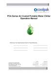
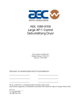
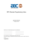
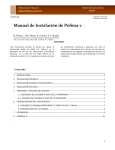
OPERATION AND INSTALLATION MANUAL SMC SERIES AIR COOLED PORTABLE WATER CHILLERS IMPORTANT: PLEASE READ CAREFULLY BEFORE ATTEMPTING TO INSTALL OR OPERATE EQUIPMENT Sterling, Inc. is committed to a continuous program of product improvement. Specifications are subject to change without notice. Effective 10-1-2007 Page 2 © Sterling, Inc. 2003 All Rights Reserved Part Number 882.00740.00 Bulletin: SC2-615A.4 SMC Series Chillers Safety Considerations Sterling, Inc. SMC Series Chillers are designed to provide safe and reliable operation when installed and operated within design specifications, following national and local safety codes. To avoid possible personnel injury or equipment damage when installing, operating or maintaining this equipment, use good judgment and follow these safe practices: ; Follow all SAFETY CODES. ; Wear SAFETY GLASSES and WORK GLOVES. ; Use care when LOADING, UNLOADING, RIGGING, or MOVING this equipment. ; Operate this equipment within design specifications. ; OPEN, TAG, and LOCK ALL DISCONNECTS before working on equipment. It is a good idea to remove the fuses and carry them with you. ; Make sure the chiller is properly GROUNDED before switching power on. ; When welding or brazing in or around this equipment, be sure VENTILATION is ADEQUATE. PROTECT adjacent materials from flame or sparks by shielding with sheet metal. An approved FIRE EXTINGUISHER should be close at hand and ready for use if needed. ; The refrigeration system can develop refrigerant pressures in excess of 500 PSI (3,450 kPa). DO NOT CUT into the system without first relieving pressure. ; Do not jump or bypass any electrical safety control. ; Do not restore power until all tools, test equipment etc. have been removed and the panels replaced. ; Only PROPERLY TRAINED personnel familiar with the information within this manual should work on this equipment. SMC Series Chillers Page 3 Table of Contents 1 General Information ................................................. 7 1-1 1-2 1-3 1-4 1-5 1-6 1-7 1-8 1-9 2 Chiller Installation .................................................. 13 2-1 2-2 2-3 2-4 2-5 3 Electrical Connections Process Water Connections SMC Condenser Air Supply Water Reservoir Overhead Process Considerations Sequence of Operation .......................................... 17 3-1 3-2 3-3 3-4 3-5 Page 4 Introduction Necessary Documents Models Covered Available Options Uncrating Your New Chiller In the Event of Shipping Damages If the Shipment is Not Complete If the Shipment is Incorrect Returns Chilled Water Circuit Refrigeration Circuit High Pressure Cutout Low Pressure Cutout Remote Start/Stop Interlock SMC Series Chillers Table of Contents 4 Startup Checklists .................................................. 23 4-1 4-2 4-3 4-4 5 Microprocessor Control......................................... 25 5-1 5-2 5-3 5-4 5-5 5-6 6 Indicator Lights Switches Routine Maintenance ............................................. 32 7-1 7-2 8 Introduction Setting the Process Water Temperature LED Indicators Temperature Controller Keys Auto-Tuning SMC Series Chillers Optional Communications Optional Graphic Panel.......................................... 30 6-1 6-2 7 Introduction SMC Pre-Startup Checklist SMC Startup Checklist SMC Water Circuit Pressure Drop Table Lubrication Condenser Maintenance Troubleshooting Guide .......................................... 36 SMC Series Chillers Page 5 Charts and Figures Figure 1: SMC050 Process Pump Curves..................................................................................... 11 Figure 2: SMC100 Process Pump Curves..................................................................................... 11 Figure 3: PCA150 Process Pump Curves ..................................................................................... 11 Figure 4: SMC Cast Iron Centrifugal Pump Curve 1/3 hp (0.249 kW)........................................ 12 Figure 5: SMC Series Chiller Specifications ................................................................................ 13 Figure 6: Ethylene Glycol Curve .................................................................................................. 16 Figure 7: Overhead Piping ........................................................................................................... 17 Figure 8: SMC Component Identification .................................................................................... 20 Figure 9: Piping Schematic - 1 Pump with Reservoir................................................................... 21 Figure 10: Piping Schematic - 1 Pump Without Reservoir........................................................... 22 Figure 11: Piping Schematic - No Pump, No Reservoir............................................................... 23 Figure 12: Typical SMC Series E5CK Microprocessor Controller .............................................. 27 Figure 13: Optional Graphic Panel ............................................................................................... 32 Figure 14: Typical SMc Subpanel ................................................................................................ 33 Figure 15: Typical SMc Wiring Schematic .................................................................................. 34 Figure 16: SMC Wiring Schematic for Chillers with No Pump or Reservoir .............................. 35 Page 6 SMC Series Chillers 1 1-1 General Information Introduction Sterling, Inc.'s SMC Series Water Chillers are reliable, accurate, and easy-to-use air cooled chillers designed for use with water/glycol. Standard range of operation is 30°F (-1°C) to 65°F (18°C) for applications using glycol and 45ºF (7ºC) to 65°F (18°C) for water-only applications. A crankcase pressure regulating valve option is available for processes requiring a leaving water temperature of up to 75°F (24°C). PCA models are available in 1/2 hp (373 W), 1 hp (746 W), and 1-1/2 hp (1,118 W) models and have an internal six gallon (23 liter) reservoir. All models are self contained, fully assembled, and shipped ready to use. A properly installed, operated, and maintained SMC Series Chiller will provide many years of reliable operation. To get the most satisfaction from your new chiller, read and follow the instructions in this manual. 1-2 Necessary Documents The following documents are necessary for the operation, installation and maintenance of Sterling, Inc.'s SMC Series Chillers. Additional copies are available from AEC, Inc. Familiarize the appropriate personnel with these documents: ; This manual. ; The electrical schematic and connection diagram mounted inside the control enclosure. Typical schematics for general reference are provided in Figure 15 and Figure 16 on pages 34 and 35. ; The operation and installation manuals for installed accessories and options. ; The Customer Parts List included in the information packet. 1-3 Models Covered This manual provides operation, installation, and maintenance instructions for Sterling, Inc. SMC Series Chillers. Model numbers are on the serial tag. Please know the model number, serial number and operating voltage of your chiller if you need to contact Sterling, Inc. SMC Series Chiller models are designated by approximate compressor horsepower. A SMC050 chiller has a 1/2 hp (373 W) compressor, a SMC100 chiller has a 1 hp (746 W) compressor, and a SMC150 chiller has a 1-1/2 hp (1,118 W) compressor. SMC Series Chillers Page 7 1-4 Available Options SMC Series Chillers are available with options that tailor the unit to your requirements. Some are factory installed, some can be retrofitted in the field. Consult your local Sterling, Inc. Sales Representative. Some of these options are: Special Pumps Special pump options are available for greater pressure and flow rates. Bronze and stainless steel wetted surface standard flow pumps ranging from 30 psi (207 kPa) to 60 psi (414 kPa) are available. Reservoirs SMC Series Chillers are available without a reservoir for processes that use their own reservoir. Power Cord A 10 foot (3 meter) power cord is available to speed SMC installation. Casters Four 2 inch (5 cm) swivel casters add mobility to the SMC unit. CPR Valve A crankcase pressure regulating (CPR) valve is available for leaving water temperatures up to 75°F (24°C). 1-5 Uncrating Your New Chiller SMC Series Chillers are shipped mounted on a skid, enclosed in a plastic wrapper, and open crated on all four sides and top. ; Pry the crating away from the skid and remove. Use a pry bar to remove the blocks securing the unit to the skid. ; Lift the unit off the skid with a fork truck. Insert forks between skid and chiller from the side until they protrude beyond the opposite side of the unit. The forks must be equidistant from the center line of the unit and the unit must be balanced on the forks. ; Lift slowly and only high enough to clear the skid. Use a pry bar if necessary to remove the skid from the unit. ; Lower slowly. The unit will land on its feet or casters and can be moved into position. Page 8 SMC Series Chillers 1-6 In the Event of Shipping Damages IMPORTANT! According to the contract terms and conditions of the Carrier, the responsibility of the shipper ends at the time and place of shipment. The Carrier then assumes full responsibility of the shipment. ; Notify the transportation company's local agent. ; Hold the damaged goods and packing material for the examining agent's inspection. Do not return any goods to Sterling, Inc. before the transportation company inspection and authorization. ; File a claim against the transportation company. Substantiate the claim by referring to the agent's report. A certified copy of our invoice is available upon request. The original Bill of Lading is attached to our original invoice. If the shipment was prepaid, write us for a receipted transportation bill. ; Advise Sterling, Inc. regarding your wish for replacement. 1-7 If the Shipment is Not Complete Check the packing list. The apparent shortage may be intentional. Back-ordered items are noted on the packing list. You should have: ; SMC Series Chiller ; Bill of Lading ; Packing List ; Operating and Installation Packet Re-inspect the container and packing material to see if smaller items have been missed during unpacking. Determine that the item was not taken from the area before the shipment was checked in. Notify the Sterling, Inc. parts and service department immediately of the shortage at (262) 641-8610. 1-8 If the Shipment is Incorrect ; If the shipment is not what you ordered, contact Sterling, Inc. immediately. Include the order number and item. ; Hold the items until shipping instructions are received. SMC Series Chillers Page 9 1-9 Returns IMPORTANT! Do not return any damaged or incorrect items until you receive shipping instructions from STERLING, Inc. Page 10 SMC Series Chillers Figure 1: SMC050 Process Pump Curves Figure 2: SMC100 Process Pump Curves Figure 3: SMC150 Process Pump Curves SMC Series Chillers Page 11 Figure 4: SMC Cast Iron Centrifugal Pump Curve 1/3 hp (0.249 kW) Page 12 SMC Series Chillers Figure 5: SMC Series Chiller Specifications Optional gauge package Optional gauge package Power cable entrance, either side Side cover handle Sight glass Drain plug (3/4" NPT) PUMP PRESSURE Mini Chiller No Flow indicator (for pumpless units only) PC Series Portable Chiller ON PUMP ON COMPRESSOR ON LOW REFRIGERANT PRESSURE To Process (3/4" NPT) HIGH REFRIGERANT PRESSURE POWER OFF A0537868 NO FLOW 34" Application Engineering 18 7/16" From Process 13 7/16" (3/4" NPT) Rear View Optional Casters 20" 26" Front View Right Side View Model Number Capacity @ 65°F LWT 75°F Ambient (Btuh) Capacity @ 50°F LWT 90°F Ambient (Btuh) Nominal Chilled Water (gpm) Compressor (hp) SMC-050 8,100 4,800 1.2 1/2 /3 hp, 1.2 gpm @ 24 psig SMC-100 14,000 9,550 2.4 1 /3 hp, 2.4 gpm @ 34 psig SMC-150 25,400 16,000 3.6 1-1/2 Process Connection (inches NPT) Amp Draw 230/1/60 Running 3/4 8A 20 26 3/4 10A 20 /3 hp, 3.6 gpm @ 24 psig 3/4 12A 20 Pump Process Connection (inches NPT) Amp Draw 230/1/60 Running 3/4 8A 51 66 3/4 10A 51 3/4 12A 51 Pump Dimensions (inches) L W H Operating Weight (lbs) Shipping Weight (lbs) 34 265 265 26 34 325 325 26 34 345 345 Operating Weight (kg) Shipping Weight (kg) 86 120 120 66 86 147 147 66 86 156 156 1 1 1 Model Number Capacity @ 18°C LWT, 24°C Ambient (watts) Capacity @ 10°C LWT, 32°C Ambient (watts) Nominal Chilled Water (lpm) SMC-050 2,374 1,407 4.5 373 SMC-100 4,103 2,800 9.0 746 SMC-150 7,444 4,690 13.6 1,118 SMC Series Chillers Compressor (watts) 224 watts, 4.5 lpm @ 207 kPa 224 watts, 9.0 lpm @ 234 kPa 224 watts, 13.6 lpm @ 207 kPa Dimensions (cm) L W H Page 13 2 2-1 Chiller Installation Electrical Connections Check serial tag voltage and amperage requirements and make sure your electrical service conforms. See Figure 5 on page 13 for total running amps. Bring properly sized power leads and ground from a fused disconnect (installed by your electrician) to the main power terminal in the chiller's electrical enclosure. ; Electrical connections must comply with all applicable electrical codes ; The chiller must be grounded in accordance with NEC Article 250 ; Voltage must be within 10% of the chiller's nameplate rating. 2-2 Process Water Connections ; All external chilled water connections to the process must be of adequate size. ; See Figure 7 on page See 17 for sizing recommendations. ; The largest possible openings and passages should be provided for the flow of chilled water through platens, dies, molds or other pieces of equipment. IMPORTANT! Keep any pressure drop in external process piping to an absolute minimum for optimum unit operation. To Process Connect the TO PROCESS chilled water supply outlet to the process being cooled. From Process Connect the FROM PROCESS chilled water return inlet to the return from the process back into the chiller for cooling and recirculation. ; Sterling, Inc. recommends a strainer on the FROM PROCESS return line. Page 14 SMC Series Chillers Process Water Bypass All SMC chillers have an internal bypass device (patent pending). If the process flow becomes blocked during chiller operation, this component allows water to flow through the chiller. This protects the chiller from freeze-up, excessive pressures, and pump damage, and allows other safety features to remain effective. 2-3 PCA Condenser Air Supply SMC chillers use the surrounding air to cool the condenser. ; Condenser air entering the SMC unit should be at least 65°F (18°C). Operation with air below 65°F (18°C) can cause the low pressure cutout to shut down the chiller due to the low refrigerant pressure. ; Install the chiller in an area where there is free passage of air for condensing. ; Provide 18" (46 cm) or more clearance for the chiller's air intake. ; Make provisions to exhaust the heated air discharged from the chiller. ; Do not put the SMC unit where steam, hot air or fume exhausts will be drawn into the condenser. ; Air-cooled condensers must be cleaned frequently. Neglect reduces capacity, increases operating costs, and leads to possible chiller failure. See Chapter 7 on Page 29 for cleaning instructions. ; Normal condensing pressure with 95°F (35°C) air is approximately 180 psi (1,241 kPa) for the SMC050 and SMC100; 275 psi (1,897 kPa) for the SMC150. PCA Ambient Temperature Ranges Ambient Temperature Range Operation Storage 2-4 Minimum Temperature 65°F (18°C) 40°F (4°C) Maximum Temperature 100°F (38°C) 120°F (49°C) Water Reservoir During startup and when additional solution is required, see Figure 6 on page 16 for the recommended ethylene glycol/water solution. This chart shows the proportions needed to provide freeze protection to 20°F/°C below the desired process setpoint. ; Add a pre-mixed solution to provide freeze protection to a temperature 20°F/°C below the normal operating temperature of the chiller. ; Use industrial quality (not automotive) ethylene glycol. SMC Series Chillers Page 15 ; A corrosion inhibitor suitable for the materials in the system should be added to the glycol/water solution. ; If straight water use is desired, contact the Sterling, Inc. Engineering Department. ; The six gallon (23 liter) reservoir is not designed to withstand water pressure above 5 psi (34 kPa). ; The fill opening and vent line must be vented to the atmosphere for proper operation. Figure 6: Ethylene Glycol Curve Ethylene Glycol Required for Evaporator Freeze Protection 30% Ethylene Glycol 20% Percent by Volume 10% 0% 25° Page 16 55° 65° 45° Chilled Water Operating Temperature °F (Set Point) Normal Operating Range between 30°F - 70°F 35° SMC Series Chillers 2-5 Overhead Process Considerations If your application has chilled water or process piping above the reservoir fill and vent level, install a standpipe to a point 1’ (30 cm) above the highest point in the system. In applications where the process or its piping is 15 feet (4.6 m) or more above the reservoir, you must take steps to prevent over-pressurization of the reservoir. This condition can occur on system shutdown when the water in the system drains into the reservoir. To prevent this, install a check valve in the unit TO PROCESS line and a vacuum breaker at the high point of the return FROM PROCESS line. See Figure 7 below for more information. Note: The reserve capacity of the reservoir can hold a volume equal to 20 feet (6.1 m) of 1-inch (2.5 cm) pipe. Figure 7: Overhead Piping Vent The reservoir vent & fill line to be piped 12" above the highest point of the system. The vent line must remain open to the atmosphere. Vacuum Breaker Assembly Cap 12" Check Valve 1/8" Hole 1/4" 6" Min. Process Return Strainer Process Supply Add check valve if system piping extends 15 feet above reservoir. Indicates end piping Indicates endofofAEC Sterling piping SMC Series Chillers Page 17 3 Sequence of Operation IMPORTANT! • The SMC unit has a leaving water temperature range of 30°F (-1°C) to 65°F (18°C). Do not attempt to run the SMC unit outside this temperature range or damage to the unit may occur. • When operating the SMC unit between 30°F (-1°C) and 40°F (5°C), you must use a solution of 75% water and 25% industrial-grade ethylene glycol with a suitable corrosion inhibitor to protect the SMC unit from freeze-up. See Figure 6 on page 16 for more information. Such damage is not covered by the Sterling, Inc. warranty. 3-1 Chilled Water Circuit Figure 9, Figure 10, and Figure 11 ; Process cooling water supply and return connections are made at the pipe stubs at the rear of the chiller. ; Warm water returns from the process and enters the reservoir tank. ; The process water is pumped through the evaporator where it is cooled. ; The coolant flows to the process and returns to repeat the cycle. ; A chilled water bypass assembly (patent pending) between the supply and return lines guarantees a constant flow through the evaporator during intermittent low or no-flow conditions. ; A flow switch in units without pumps will prevent the compressor from running without adequate flow through the evaporator 3-2 Refrigeration Circuit ; Liquid refrigerant from the condenser passes through a filter/dryer which removes moisture and other contaminants. ; The refrigerant then passes through the thermal expansion valve which allows the refrigerant to expand and cool the inside of the heat exchanger. The refrigerant flows through the suction line to the compressor. ; The refrigerant gives up its heat as it re-condenses to a liquid in the condenser and the cycle starts over again. Page 18 SMC Series Chillers 3-3 High Pressure Cutout The high pressure cutout is an electro-mechanical safety feature that opens the control circuit if the system condensing pressure exceeds a safe level. The chiller will automatically restart when the pressure drops back to an acceptable level. Model SMC050 SMC100 SMC150 Cuts out if condensing pressure exceeds: 275 psi (1,897 kPa) 275 psi (1,897 kPa) 400 psi (2,759 kPa) IMPORTANT! Call a refrigeration service technician to analyze the problem if high pressure recurs. 3-4 Low Pressure Cutout The low pressure cutout is an electro-mechanical safety feature that prevents compressor suction pressure from dropping below a preset point. It is factory set to open the control circuit when pressure drops below a safe level. The chiller will automatically restart when the suction pressure reaches an acceptable level. Model SMC050 SMC100 SMC150 3-5 Cuts out if suction pressure falls below: 15 psi (103 kPa) 15 psi (103 kPa) 35 psi (241 kPa) Remote Start/Stop Interlock A contact is provided to allow interlocking of the SMC Series Chiller with process controls. To use this feature, remove the jumper between Terminals X1 and 1 on Terminal Block 1. Supply a switch or dry contact interlock connected in series between these two terminals. See Figure 15 and Figure 16 on pages 34 and 35 for more information. SMC Series Chillers Page 19 Figure 8: SMC Component Identification Page 20 SMC Series Chillers Figure 9: Piping Schematic - 1 Pump with Reservoir Air-cooled condenser Discharge line Liquid line Refrigeration evacuation valve Relief valve Refrigeration evacuation valve Filter Suction Line Expansion valve Evaporator Filter Drier Sight glass Legend Refrigeration lines Chilled water piping Condenser water piping End of unit piping Equalizing line Power element Refrigeration access valve Temperature probe TC High pressure control S Optional pressure gauge P To Process Low pressure control Bypass Optional CPR valve Compressor Refrigeration access valve, compressor-mounted Vent Fill Sight glass Tank Pump SMC Series Chillers Drain From Process Page 21 Figure 10: Piping Schematic - 1 Pump Without Reservoir Air-cooled condenser Discharge line Liquid line Refrigeration evacuation valve Relief valve Refrigeration evacuation valve Filter Suction line Expansion valve Evaporator Equalizing line Sight glass Filter drier Legend Refrigeration lines Chilled water piping Condenser water piping End of unit piping Power element Refrigeration access valve Temperature probe High pressure control TC Compressor Refrigeration access valve, compressor-mounted Pump Page 22 P S Low pressure control Optional CPR valve Optional pressure gauge To Process Bypass From Process SMC Series Chillers Figure 11: Piping Schematic - No Pump, No Reservoir Air-cooled condenser Discharge line Liquid line Refrigeration evacuation valve Relief valve Refrigeration evacuation valve Filter Suction line Expansion valve Evaporator Sight glass Filter drier Legend Refrigeration lines Chilled water piping Condenser water piping End of unit piping Equalizing line Power element Refrigeration access valve Optional pressure gauge Temperature Probe TC High pressure control P S Low pressure control To Process Bypass Optional CPR valve Compressor Refrigeration access valve, compressor-mounted Flow switch From Process SMC Series Chillers Page 23 4 4-1 Startup Checklists Introduction Follow the check lists below for the startup of your new chiller. These lists assume the installation information elsewhere in this manual has been read and followed. New chillers should be started up and checked by a qualified refrigeration service technician. 4-2 SMC Pre-Startup Checklist 1. Check the shipping papers against the serial tag to be sure chiller size, type and voltage is correct for the process that will be controlled. 2. Check the transformer primary voltage connections to be sure they are configured for the electrical power you are using. The voltage at the main power connection must read within +/-10% of the voltage listed on the serial tag. Electrical connections must conform to all applicable codes. 3. The chilled water TO PROCESS and FROM PROCESS connections should be completed. 4. Be sure the reservoir tank and chilled water circuit piping are filled with water. 5. The air-cooled condenser should have an adequate supply of air for proper operation. 6. Connect main power to the chiller and run the chiller just long enough to see if the pump is generating normal pressure. 7. Check your work and proceed to the SMC Startup Checklist section below. 4-3 PCA Startup Checklist 1. Turn ON the chiller. The SMC chiller should continue to run until the switch is turned OFF. 2. Put the SMC chiller under a process load. 3. Set the microprocessor control to the desired process temperature setpoint using the , , and buttons. See Chapter Five on Page 25 for more information. 4. Check the pump amp draw and pump pressure. The amp draw reading must be within the running load and service factor amps. 5. Operate the chiller, looking for leaks and listening for unusual noises or vibrations that could indicate improper operation. Page 24 SMC Series Chillers 4-4 SMC Water Circuit Pressure Drop Table Model SMC050 SMC100 SMC150 Gallons per minute 2.0 2.4 3.6 4.8 2.0 2.4 3.6 4.8 2.0 2.4 3.6 4.8 SMC Series Chillers Liters per minute 7.5 9.0 13.6 18.1 7.5 9.0 13.6 18.1 7.5 9.0 13.6 18.1 ΔP (psig) 2.5 4.0 7.5 12.5 2.5 2.5 3.0 5.0 2.5 2.5 3.0 3.5 ΔP (kPa) 17.3 27.6 51.8 86.2 17.3 17.3 20.7 34.5 17.3 17.3 20.7 24.2 Page 25 5 5-1 Microprocessor Control Introduction Standard SMC Series chillers use a microprocessor-based PID controller. The controller is a modular, self-contained unit that can slide from its mounting housing. It is factory set and adjusted; no field adjustment to the internal controls is necessary. SMC Control Operation Range Standard models 30°F to 65°F (-1ºC to 18ºC) 5-2 Setting the Process Water Temperature To change the process water temperature set point: 5-3 • Press the Up Arrow button to raise the set point. • Press the Down Arrow button to lower the set point. LED Indicators PV or Process Value Numeric LED During normal operation, the large red PV LED on the controller displays the actual process temperature at the To Process thermocouple. It also lists parameter symbols during setup and error messages if an error occurs. SV or Set Value Numeric LED During normal operation, the green SV LED on the controller displays the process set point you want the chiller to maintain. It also displays parameter and pre-set function values during setup. OUT1 LED The orange OUT1 LED lights when the control output energizes the hot-gas bypass solenoid valve. Page 26 SMC Series Chillers Figure 12: Typical SMC Series E5CK Microprocessor Controller PV OUT1 SV OUT2 MANU STOP RMT AT SUB1 AT OMRON E5CK OUT2 LED The orange OUT2 energizes whenever the process temperature is two degrees (2°F/ºC) or more above the To Process set point. The compressor then comes on and runs until the temperature at the To Process thermocouple is two degrees (2°F/ºC) below the set point. This +2°F/ºC control set point is factory-set for proper compressor operation. Changing it is not recommended without consulting the AEC Service Department. MANU LED The orange MANU LED does not light because it is not used. STOP LED The orange STOP LED does not light because it is not used. SMC Series Chillers Page 27 RMT LED The orange RMT LED is lit during remote operation. AT LED The orange AT LED flashes during auto-tuning. SUB1 LED The orange SUB1 LED energizes whenever the process temperature is two degrees (2°F/ºC) or more below the To Process set point. The compressor then shuts down by means of a latching circuit, and does not run again until the temperature at the To Process thermocouple is two degrees (2°F/ºC) above the set point. This +2°F/ºC control set point is factory-set for proper compressor operation. Changing it is not recommended without consulting the Stelring Service Department. 5-4 Temperature Controller Keys AT AT Key Press and hold the AT AT key for two seconds to initiate or stop the auto-tune function. Display Key The functions of the Display key change, based on how long you press it. Press the Display key for less than one (1) second to scroll through parameters within the mode. Press the Display key for at least one (1) second or more to display the menu; this function also lets you select the mode you need to adjust. Page 28 SMC Series Chillers Important! Do not change any of the control settings without consulting the Sterling Service Department. The AEC, Inc. warranty does not cover chiller failures from tampering with controller settings! Down Key Each press of the Down Arrow key decrements or reduces the values or settings on the SV display. Up Key Each press of the Up Arrow key increments or advances the values or settings on the SV display. 5-5 Auto-Tuning SMC Series Chillers The Auto-Tune function lets you fine-tune the control PID to process requirements. Activate the Auto-Tune function whenever the process under control changes. Don't be alarmed by control response. It may take the process temperature above and below the set points as many as three (3) times. It will then level off and control to the process set point. Auto tuning can take up to 45 minutes, and is best done before any product is being run. Important! Factory default settings are: P = .3, I = 7, and D = 1 To auto-tune the controller: Press and hold down the the AT indicator flashes. AT AT key for several seconds until The AT LED flashes to indicate that the control is tuning itself.When the AT LED light stops flashing, the controller is tuned and ready for operation. SMC Series Chillers Page 29 5-6 Optional Communications Standard Omron Protocol The communications function allows you to monitor and set E5CK parameters by a program prepared and running on a host computer connected to the E5CK controller. When using the communications function, you must add on the unit for RS-232C or RS-485 communications. The E5CK communications function allows you to read/write parameters, do operating instructions, and select the setting level. Page 30 SMC Series Chillers 6 6-1 Optional Graphic Panel Indicator Lights PUMP ON (green) This indicator lights when the pump is running. COMPRESSOR ON (green) This indicator lights when the compressor is operating. HIGH REFRIGERANT PRESSURE (red) This indicator lights if the condensing pressure exceeds a safe level. The chiller goes to Idle mode until the high refrigerant pressure cutout resets. The light then goes out and the chiller automatically restarts. Call a qualified refrigeration service technician for service. LOW REFRIGERANT PRESSURE (red) This indicator lights if the refrigerant pressure drops below a safe level. The compressor will stop and remain off until the pressure reaches a safe level. The light will go out and the chiller will then resume operation automatically. LOW WATER FLOW (red), PCA units without pump only This indicator lights if the flow switch senses chilled water/glycol flow through the evaporator dropping to an unacceptable level. The compressor will stop until the flow switch senses adequate flow and restarts the chiller. 6-2 Switches POWER This switch energizes the control circuit and also turns off the chiller. SMC Series Chillers Page 31 Figure 13: Optional Graphic Panel PC Series ON Portable Chiller ON PUMP ON AL O RO E5CS COMPRESSOR ON LOW REFRIGERANT PRESSURE HIGH REFRIGERANT PRESSURE POWER OFF A0537868 Page 32 SMC Series Chillers 7 Routine Maintenance 7-1 Lubrication Every three months, grease all fan motors and pump motors that do not have permanently sealed bearings. Remove grease relief plug (motors only) before adding grease. Failure to do so may result in dislodging the bearing grease retainer, eventually causing bearing failure. Compressors are hermetically sealed; no oiling is required. 7-2 Condenser Maintenance Dirty condenser heat exchange surfaces reduce system capacity. Brush or vacuum light dirt accumulations. Avoid bending or damaging the fins. Heavy soil accumulations on the coil require professional steam cleaning; washing from the outside only makes matters worse. Figure 14: Typical SMC Subpanel Distribution Block Grounding Lug Terminal Blocks Control Voltage Transformer Pump Contactor SMC Series Chillers Condenser Contactor Page 33 Figure 15: Typical SMC Wiring Schematic 1C 1L1 1T1 1L2 1MTR Pump 2MTR Compressor 3MTR Fan 1T2 2C 1L1 2T1 1L2 2T2 3T1 Earth ground 3T2 Remote interlock by others 1L2 1L1 230V Control power ON/OFF 1S-1LT 1T Jumper 1 1FU X1 1 115V 2 G 3 1 1S-1LT G R 4 1 1PS "Hi Refrig Pres" 3LT R G 5 1 2PS G 1 7 1 8 1 9 1 2 1 3 1 "Pump On" 61 Condensing unit contactor 2C 5LT "Compressor On" 1 10 Jumper 1CNTL 2LT 4LT G 6 1 "Power On" Pump starter 1C "Low Refrig Pres" Subpanel ground 2 Legend 4 1 5 1 Customer wiring/Customer-supplied components Optional components (+) YEL (-) RED Type K Thermocouple Page 34 SMC Series Chillers Figure 16: SMC Wiring Schematic for Chillers with No Pump or Reservoir 1C 1L1 1L2 1L2 1MTR Compressor 2MTR Fan 1T2 1L1 2T1 Remote interlock by others Earth ground 1T1 2T2 230V Control power ON/OFF 1T Jumper 1S-1LT 1 1S 1FU 2 2 115V X1 G 31 "Low Refrig Pres" 3LT R "No Flow" R 4 1FLS 2LT 5 5 1PS 1S-1LT Subpanel ground "Power On" "High Refrig Pres" 4LT R 6 2PS 7 Condensing unit contactor 1C G 5LT "Compressor On" 2 Legend 6 7 8 9 10 Jumper 1 (+) YEL 2 3 Customer wiring/Customer-supplied components 1CNTL 4 Optional components 5 (-) RED Type K thermocouple SMC Series Chillers Page 35 - Notes - Page 36 SMC Series Chillers 8 Troubleshooting Guide Problem Chiller will not run. Cause No power. Wrong voltage supplied to the chiller. Defective on/off switch. Control circuit fuse blown. Pump runs, compressor cycles at short intervals. Defective control transformer. No process load on the chiller. Refrigerant is low. The leaving water temperature is too high. Refrigerant is low. Improper water/glycol solution. Pump pressure is low (see pump curves). Pump pressure is too high. SMC Series Chillers Solution Check main disconnect fuses, wiring, and power lead to the unit. Voltage must be within plus or minus 10% of the nameplate rating. Replace. Replace, check the transformer. Replace. Increase the process load. Check the refrigerant charge. Check the refrigerant charge. Make sure that the coolant solution is right for the process — must be 75% water and 25% glycol. See Figure 6 on page 16 for more information. Check for foreign matter. Clean the system. Restricted water flow. Check for partially closed valves, etc. Be sure all lines are properly sized. Page 37 Problem Pump runs, compressor will not. Cause Refrigerant is low. Pressure switch contacts are open. Refrigerant high pressure cutout switch contacts are open. Defective fan motor. Compressor internal overload is open. Allow time to cool and reset. Unit runs continuously, but not enough cooling power. Page 38 Broken wire in the compressor control circuit. Restricted condenser airflow. Unit low on refrigerant. Inefficient compressor. Unit undersized for application. Solution Check the refrigerant charge. Sight glass should be clear while compressor runs. Call for service if bubbling or foaming Check for dirty condenser. Check for condenser air obstruction. Repair or replace. Check for high/low voltage. Must be within plus or minus 10% of the nameplate rating. Check for poor compressor electrical connections. Locate and repair. Clean the condenser. Call Service. Call Service. Call Sales Representative. SMC Series Chillers PCA Unit Parts List Part Number A0537868 A0537899 A0534584 A0534586 A0500857 A0534269 A0537955 A0533873 A0539409 A0103778 A0537900 A0537908 A0537915 A0543063 A0537916 A0537917 A0501642 A0104093 A0537974 Part Description SMC Graphic BZ Pressure Gauge Red Neon Graphic Light * Green Neon Graphic Light * 2” Swivel Casters 1/16 DIN Digital Temperature Controller Process Water Flow Switch Thermocouple, 8’ 150 VA Transformer Rubber Feet Tank Sight Glass Assembly Handles SMC050-100 Low Refrigerant Pressure Switch SMC150 Low Refrigerant Pressure Switch SMC050-100 High Refrigerant Pressure Switch SMC150 High Refrigerant Pressure Switch SMC050-100 High Refrigerant Pressure Safety Relief Valve SMC150 High Refrigerant Pressure Safety Relief Valve Bronze Y Strainer * Units with the optional SMC graphic panel. SMC Series Chillers Page 39 - Notes - Page 40 SMC Series Chillers - Notes - SMC Series Chillers Page 41 -Notes - Technical Assistance Page 42 SMC Series Chillers Parts Department Call toll-free 7am - 5pm CST [800] 423-3183 Or call [262] 641-8610, Fax [262] 641-8653 The Parts Department at AEC, Inc. is ready to provide the parts to keep your systems up and running. AEC replacement parts ensure operation at design specifications. Please have the model and serial number of your equipment when you call. Consult the Customer Parts List included in your information packet for replacement part numbers Service Department Call toll-free 8am - 5pm CST [800] 423-3183 Or call [262] 641-8610 Emergencies after 5pm CST, call [847] 439-5655 AEC has a qualified service department ready to help. Service contracts are available for most AEC products. www.acscustomerservice.com Sales Department Call [262] 641-8610 Monday - Friday 8am -5pm CST AEC products are sold by a world-wide network of independent sales representatives. Contact our Sales Department for the name of the sales representative nearest you. Contract Department Call [262] 641-8610 Monday - Friday 8am - 5pm CST Let AEC install your system. The Contract Department offers any or all of these services: project planning; system packages including as-built drawings; equipment, labor and construction materials; union or non-union installations; and field supervision Sterling, Inc. 2900 S. 160th Street New Berlin, WI 53151 [262] 641-8610 • Fax [262] 641-8653 SMC Series Chillers Page 43