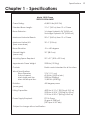
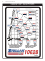
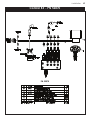
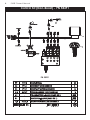
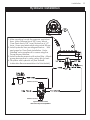
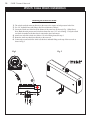
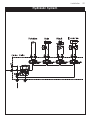
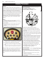
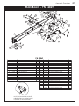
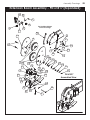
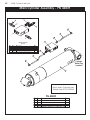
1
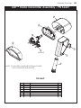
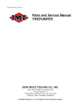
Model 10628
Telescopic crane
owners’ Manual
installation • assembly drawings • parts
®
TM
Stellar Industries, Inc.
Subject to Change without Notification.
© 2012 Stellar Industries, Inc.
190 State Street
PO Box 169
Garner, IA 50438
800-321-3741
Fax: 641-923-2811
www.stellarindustries.com
Last Revision: 09/17/12
10628 Manual Revisions
Date of Revision
Section Revised
Description of Revision
September 15th, 2011
Chapter 2: Installation
Chapter 3: Assembly
Drawings
New Flip Sheave Design Implemented. Updated Extention
Boom, Mast, Cable & Hook Assembly Drawings.
Table of Contents
Table of Contents
Chapter 1 - Specifications ......................................................................1
Capacity Chart - Decal PN 54496....................................................2
Chapter 2 - Installation ...........................................................................3
Installation Overview ..........................................................................4
Control Kit - PN 52870 .........................................................................5
Control Kit (Non-Boost) - PN 58291 ...................................................6
Hydraulic Kit - PN 52264 .....................................................................7
Valve Bank - PN 52265........................................................................8
Hydraulic Installation ..........................................................................9
Winch Case Drain Installation .........................................................10
Hydraulic System...............................................................................11
Stability Procedure............................................................................12
Decal Kit Placement - PN 54762 .....................................................13
Chapter 3 - Assembly Drawings ..........................................................15
Base Assembly - PN 18027 ...............................................................15
Mast Assembly - PN 52488 ...............................................................16
Main Boom - PN 52869 .....................................................................17
Extension Boom Assembly - PN 61817 ............................................18
Extension Boom Assembly - PN 61817 (Expanded) ......................19
Main Cylinder Assembly - PN 43839 ...............................................20
Extension Cylinder Assembly - PN 28856 ........................................21
Cable & Hook Assembly - PN 55898...............................................22
CDT™ Radio Transmitter Assembly - PN 56647..............................23
Chapter 4 - Replacement Parts ...........................................................25
For Technical Questions, Information, Parts, or Warranty, Call Toll-Free at
800-321-3741
Hours: Monday - Friday, 8:00 a.m. - 5:00 p.m. CST
Or email at the following addresses:
Technical Questions, and Information
Order Parts
Warranty Information
[email protected]
[email protected]
[email protected]
i
ii
10628 Owner’s Manual
Specifications
Chapter 1 - Specifications
Model 10628 Crane
SPECIFICATION SHEET
Crane Rating:
60,000 ft-lbs (8.29 TM)
Standard Boom Length:
12’ 6” (3.81 m) from CL of Crane
Boom Extension:
1st stage: Hydraulic 96" (243.8 cm)
2nd stage: Hydraulic 96" (243.8 cm)
Maximum Horizontal Reach:
28’ 6” (8.69 m) from CL of Crane
Maximum Vertical Lift:
(from crane base)
30’ 4” (9.24 m)
Boom Elevation:
-5 to +80 degrees
Stowed Height:
(crane only)
35” (88.9 cm)
Mounting Space Required:
20” x 21” (50.8 x 53.3 cm)
Approximate Crane Weight:
2900 lbs (1315 kg)
Controls:
Radio control standard for all functions.
Winch Specifications
Rope Diameter:
Line pull speed:
Max. single part line:
Max. double part line:
7/16" (1.11 cm)
60 ft/min (18.29 m/min)
5000 lbs (2268 kg)
10,000 lbs (4535 kg)
Rotation:
(worm gear)
400 degree power
Lifting Capacities:
4875 lbs @ 12’ 6” (2210 kg @ 3.81 m)
2950 lbs @ 20’6” (1335 kg @ 6.25 m)
2115 lbs @ 28’ 6” (960 kg @ 8.69 m)
Power Supply Required:
PTO & Pump
(8 gpm @ 3000 psi)
(30.3 lpm @ 207 bar)
*Subject to change without notification
1
2
10628 Owner’s Manual
Capacity Chart - Decal PN 54496
10000 lbs
4535 kg
Reach in Feet/Meters
Capacity in Pounds/Kilograms
8735 lbs
3960 kg
7405 lbs
3355 kg
Boost
(If Equipped)
4765 lbs
2160 kg
4040 lbs
1830 kg
10000 lbs
4535 kg
9950 lbs
4515kg
10000 lbs
4535 kg
30' 4”
9.25 m
Standard
24'
7.01 m
3505 lbs
1585 kg
2970 lbs
1345 kg
6525 lbs
2955 kg
27'
8.23 m
21'
6.40 m
5530 lbs
2505 kg
10000 lbs
4535 kg
10000 lbs
4535 kg
4860 lbs
2205 kg
4120 lbs
1870 kg
10000 lbs
4535 kg
8760 lbs
3975 kg
80º
3935 lbs
1780 kg
7945 lbs
3600 kg
6735 lbs
3055 kg
75º
60º
45º
30º
15º
3335 lbs
1510 kg
6400 lbs
2900 kg
5425 lbs
2460 kg
3'
6'
9'
.914m 1.83 m 2.74 m
3580 lbs
1620 kg
2560 lbs
1160 kg
2170 lbs
985 kg
3035 lbs
1375 kg
12'6”
3.81 m
Weight of load handling devices are
part of the load lifted and must be
deducted from the capacity.
18'
5.49 m
15'
4.57 m
12'
3.66 m
9'
2.74 m
6'
1.83 m
5875 lbs
2660 kg
4980 lbs
2260 kg
5750 lbs
2605 kg
4875 lbs
2210 kg
0'
0m
2840 lbs
1285 kg
2410 lbs
1095 kg
3'
.914
3480 lbs
1575 kg
2950 lbs
1335 kg
20'6”
6.25 m
2495 lbs
1130 kg
2115 lbs
960 kg
28'6”
8.69 m
Maximum 1 - part line capacity is
5000lbs (2270kg). For greater
loads, use 2 - part line.
PN 54496
Installation
3
Chapter 2 - Installation
Notice: Read this Page Before Installation of the Crane
General Installation
Installation Notice
This chapter is designed to serve as a
general guide for the installation of a Stellar
10628 Telescopic Crane on a Stellar Service
Body. Each installation is considered unique
so certain portions of this chapter may or
may not apply to your direct application. If
a question should arise during the installation
process, please contact Stellar Customer
Service at (800) 321 3741.
This crane is designed for use with a Stellar
Service Body installed on a vehicle that
meets the minimum chassis requirements of
the crane. It is the installer’s responsibility to
assure that the crane is mounted on a
platform that will support the maximum
crane rating of this crane.
Notice:
PTO and Pump installation instructions are
provided by the corresponding
manufacturers. For more information on
which PTO and Pump fit your application,
please contact your local Stellar Distributor
or Stellar Customer Service.
According to Federal Law (49 cfr part 571),
each final-stage manufacturer shall
complete the vehicle in such a manner that
it conforms to the standards in effect on the
date of manufacture of the incomplete
vehicle, the date of final completion, or a
date between those two dates. This
requirement shall, however, be superseded
by any conflicting provisions of a standard
that applies by its terms to vehicles
manufactured in two or more stages.
Therefore, the installer of Stellar cranes and
bodies is considered one of the
manufacturers of the vehicle. As such a
manufacturer, the installer is responsible for
compliance with all applicable federal and
state regulations. They are required to
certify that the vehicle is in compliance with
the Federal Motor Vehicle Safety Standards
and other regulations issued under the
National Traffic and Motor Vehicle Safety
Act.
Please reference the Code of Federal
Regulations, title 49 - Transportation, Volume
Important: When installing welder units to the service
5 (400-999), for further information, or visit
bodies, it is highly recommended that a surge
protector is installed on the chassis batteries to protect http://www.gpoaccess.gov/nara/index.html
the crane radio receiver, wiring and other electronic for the full text of Code of Federal
devices from an unexpected electrical spike or surge. Regulations.
Failure to do so could result in extensive damage to
the service body and crane electrical circuit.
4
10628 Owner’s Manual
Installation Overview
1. Determine that the mounting location for the 10628 crane is at least 20” x 21” (50.8 x 50.8 cm).
2. Use the detail below to drill 1.06” diameter holes into the mounting plate. Run tap on the threads of the
base to be sure they are clean.
3. Use a crane or lifting device capable of lifting the weight of the Stellar crane. The Stellar 10628 weighs
approximately 2900 lbs (1315 kg). Note: cranes are shipped with rotation positioned at 200 degrees of 400
degree system. This will allow for easy installation of the crane and permanent connection of all hydraulic
and electrical components prior to repositioning into the crane saddle.
4. Connect straps or chain from the lifting device to the lifting rings on the Stellar 10628.
5. Use six (6) 3” x 1” #8 bolts and six (6) #8 flat washers.
6. Install a washer on each bolt.
7. Apply Loctite Thread locker #277 to the bolts.
8. Using the lifting device, lower the Stellar 10628 just above the crane compartment and start the bolts.
Have someone assist in leveling the crane. Note: the rotation motor should be to the door side of crane
compartment and the boom should be extended back over the rear bumper.
9. Secure the crane using the mounting hardware provided. Note: longer or shorter cap screws may be
required – recommended thread engagement into crane base is 1.75” – use grade 8, zinc plated cap
screws only.
10. Torque the cap screws to 680 ft-lbs.
11. Remove supporting crane.
12. Hook-up hydraulics and electrical using the schematics provided in Chapter 8 - Hydraulics - Electrical.
Note: If questions should arise during any portion of this installation, please contact Stellar Customer
Service at (800) 321-3741.
WARNING!
The use of this crane on a
body not capable of handling
the loads imposed on it may
result in serious injury or
death.
Front
1.063
6 Places
13.75
14.75
7.38
6.88
6.00
2
1
Motor
2.38
7.38
14.75
PN 13539
ITEM
1
2
PART
5199
6538
DESCRIPTION
CAP SCR 1.00X8X3.00 HHGR8 ZY
WASHER 1.00 SAE FLAT YELLOW GR8
QTY.
6
6
NOTE: STABILITY DECAL P/N 16881 IS PART OF THIS KIT
Installation
Control Kit - PN 52870
PN 52870
5
6
10628 Owner’s Manual
Control Kit (Non-Boost) - PN 58291
PN 58291
Installation
Hydraulic Kit - PN 52264
NOTE: USE 32" OF HOSE PROTECTOR
P/N 17288 OVER THE ROTATION HOSES
NOTE: USE 12" OF HOSE PROTECTOR
P/N 17288 OVER THE 3 WINCH HOSES
PN 52264
7
8
10628 Owner’s Manual
Valve Bank - PN 52265
HYDRAULIC SCHEMATIC
4
2
1
3
4
3
4
3
PN 52265
ITEM PART
1
25367
25368
2
24960
25369
3
25371
25373
4
44532
DESCRIPTION
RELIEF VALVE 24685/24690
SEAL KIT 25367
VALVE FLW CTRL PRP/JP04C3150N 0-8
SEAL KIT 24960/25381
VALVE SOLND 3 POS 4 WAY TAND G04571
SEAL KIT 25371/25372
COIL 12VDC DUETSCH CAP012H
QTY
1
1
4
9
Installation
Hydraulic Installation
1. After mounting, locate the pressure and return
lines. Note: Pressure line is 3/8” hose; Winch
Case Drain Line is 3/8” hose; Return line is 1/2”
hose. Hoses are terminated using swivel fittings.
2. Install hydraulic lines per diagram below. See
next page for Case Drain Installation. Note:
Stabilizer valve supplies oil to crane using the
Power Beyond feature.
3. Install hydraulic reservoir with return filter. Attach
pump pressure line to valve, return link to tank.
4. Fill system with hydraulic oil (See Stellar®
Lubrication Recommendations for fluid details).
(Blue)
Stabilizer Functions
Stabilizer Functions
Typical Stabilizer Valve
with Power Beyond Capabilities
9
10628 Owner’s Manual
Winch Case Drain Installation
Installing the winch case drain
1. The winch case drain must run directly to the reservoir to ensure no back pressure in the line.
2. Use 3/8” hydraulic hose and fittings rated for a minimum of 300 psi.
3. Locate the winch case drain line at the bottom of the crane base as shown in Fig. 1 (Blue Hose).
Note: Both the main pressure and winch case drane line use a 3/8” swivel fitting. Verify the winch
case drain is attached to the hose that is connected to the winch motor.
4. Attach one end of the winch case drain to 3/8 swivel fitting located in step 3.
5. Route the winch case drain hose directly to the reservoir.
6. Connect the second end of the winch case drain to unshared fitting on the top of the reservoir as
shown in Fig 2.
Fig.1
Fig. 2
(Blue)
10
Installation
Hydraulic System
11
12
10628 Owner’s Manual
Stability Procedure
Definition of Stability for the Stellar Telescopic Crane
Products:
A truck is stable until the load cannot be lifted off
the ground with the winch, without tipping over the
truck. Every Stellar crane installed must be tested for
stability to determine the actual load capacity of
the final truck package. The actual test data must
be recorded and supplied with the truck at the time
of in-service and should be kept with the truck at all
times. The following procedure will test the truck
package for stability and will provide a stability
capacity chart. The load limit information shown on
the stability capacity chart is formulated on 85%
tipping.
Set Up:
1. Locate the truck on a test course in position for
loading and engage travel brakes.
2. Set stabilizers so that they make contact with firm,
level footing.
3. Operate the crane under partial load to assure
operator proficiency and proper machine
function.
4. Put the radio into Stability Test Mode:
A. Push the bottom four switches up and hold until
all lights come on (approximately 5 seconds.)
B. At this point ,the crane will have enough
capacity to handle the weight for the stability
test.
C. The radio will timeout of stability mode after 30
minutes or when the E-Stop button is pushed.
Note: The radio can only be put into stability mode
five times. After that, the radio would have to be
returned to Stellar to be reprogrammed to allow
additional stability testing. All other radio functions
will work properly even if stability mode is not available.
10628 Stability Data
Max Horizontal Reach: 342” (From the center of
rotation to boom tip)
Boost Stability Test Weight: 2945 lbs.
Non-Boost Stability Test Weight: 2495 lbs.
Test Procedure
1. Rotate the crane into Zone 1 position.
2. With the crane fully retracted and the boom
horizontal, winch the test weight off the ground.
Note: Keep weight within six inches of the ground
at all times.
3. Extend the boom outward until full extension has
been reached or until the truck becomes unstable
(Again, use the winch to keep the weight within six
inches of the ground.)
4. If the boom goes full extension without becoming
unstable, the crane is termed stable for this zone
and 100% can be written in the Zone 1 data box.
5. If the truck becomes unstable prior to going full
extension, retract the boom until the truck
becomes stable and measure the horizontal
reach in this position (center of rotation to boom
tip). This is the stable horizontal reach for this zone.
Stable horizontal reach divided by Maximum
horizontal reach multiplied by 100 equals the
percentage of rated capacity for this zone. Use
the following formula to determine the
percentage of rated capacity:
6. Record this number in the data box for Zone 1.
This is the revised capacity due to stability for this
zone.
7. Repeat this procedure for each zone until the
worksheet is completed.
8. This is the revised capacity based on stability of
this package.
Installation
13
Decal Kit Placement - PN 54762
30
14,15
Angle Indicator
80 70
®
60
50
40
30
20
10
10628
22
0
3
2
33
27
1
28
26
9
25
29
**THESE DECALS NOT INCLUDED WITH THE DECAL KIT
PN 54762
*USE THESE DECALS WITH BODY PACKAGE
33
54588
DECAL CDT 2.00X2.00
2
*16
12451
DECAL HOISTING PERSONNEL
1
32
25159
DECAL WARNING MANUAL OVERRIDES
1
15
D1197
DECAL-ANGLE INDICATOR SS
1
31
52270
DECAL VB CONTROL MECH CRANE
1
14
D1196
DECAL ANGLE INDICATOR CS
1
30**
35234
DECAL STELLAR MADE IN THE USA
1
*13
C1179
DECAL-ELECTROCUTION 4.5x7.5
2
29
56405
DECAL SNATCH BLOCK CAP 7 TON
1
*12
C5918
DECAL-DANGER MOVING O.R.
2
28
28256
DECAL WARNING OVERLOAD DEVICE
1
*11
C4795
DECAL-DANGER O.R.
2
27
24712
DECAL CAUTION STOW HOOK
1
*10
4190
DECAL-DANGER
1
26
15172
DECAL ASME/ANSI B30.22/B30.5
1
09
9188
DECAL-ROTATE/GREASE
1
25
15171
DECAL GREASE WORM DRIVE BEARINGS
1
*08
4189
DECAL-DANGER
1
24
4188
DECAL-ROTATION ALIGNMENT
1
*07
4186
DECAL-ELECTROCUTION 2x2.75
1
*23
C4541
DECAL-CRANE STOWING
1
*06
C4544
DECAL-DANGER
1
22
12300
DECAL-TWO BLOCKING
1
*05
C4540
DECAL-DANGER
1
*21
4214
*04
C4545
DECAL-ELECTROCUTION 5x13
4
*20
*03
54496
DECAL CAPACITY
2
02
52687
DECAL 10628 IDENTIFICATION
2
52681
DECAL STELLAR LOGO 6.5 x 18
2
*17
ITEM
01
ITEM
PART No.
DESCRIPTION
QTY
DECAL-SERVICE
1
C0568
DECAL-DIESEL
2
*19
12452
DECAL MANUAL EXT
1
*18
C5911
DECAL-STELLAR 2x4.5
3
C5910
PART No.
DECAL-STELLAR 4x9.5
DESCRIPTION
1
QTY
14
10628 Owner’s Manual
Assembly Drawings
Chapter 3 - Assembly Drawings
Base Assembly - PN 18027
5
6
8
7
2
1
9
10
4
10
12
3
11
14
PN 18027
ITEM
1
2
3
4
5
6
7
8
9
10
11
12
13
14
PART
11453
11542
C6069
D1307
44551PC
13959
0340
0479
21151
D1345
D1810
C2 25 6
D0790
56589
DESCRIPTION
BEARING SWING DRIVE CAST BASE 6620
STOP 3820 400 SLIDE
MOTOR HYD ROSS MK080613AAAB
CAP SCR 0.50-13X1.25 SH
GUARD TTB 6620 CRANE LZR
CAP SCR 1.00-8 X .63 PLASTIC
WASHER 0.25 FLAT
CAP SCR 0.25-20X0.75 HHGR5
GASKET MOTOR 008-10056-1
FTG CPRSN 0.12NPT/0.25 TUBE
TBE AIR SAEJ844 TYPE A .25 (RM)
FTG C OU PLER PIPE 0.13
WASHER 0.50 FLAT GR8
ZERK 1/8 NPT STRAIGHT LONG THREAD
GASKET SHOWN AS REFERENCE
QTY.
1
1
1
2
1
2
2
2
1
2
1
1
2
1
15
16
10628 Owner’s Manual
Mast Assembly - PN 52488
11
9
3
10
7
5
2
5
1
6
12
4
3
8
DO NOT GREASE
THESE BUSHINGS
PN 52488
ITEM
1
2
3
4
5
6
7
8
9
10
11
12
PART
43483
27813
C5902
D1034
0343
C0933
0342
44533
11693
52490
57917
52265
DESCRIPTION
QTY.
MAST 10621/12621
1
COLLAR 0.38X0.75X0.38 UHMW
2
WASHER 0.63 SAE FLAT YELLOW GR8
18
CAP SCR 0.63-11X3.00 HHGR8 RED PATCH 14
WASHER 0.31 USS FLAT ZINC
4
CAP SCR 0.31-18X4.50 HHGR5
2
NUT 0.31-18 HHGR5 NYLOC
2
BUSHING HSG3235012S 2.00X0.75
4
CAP SCR 0.63-11X1.75 HHGR8
4
CAP SCR 6MMX30MM HH 8.8(GR5)
4
WINCH 5000 TH2CC00243 W/100 FT ROPE
1
VB 4 SECT W/PROP STER8GPM DEUTSCH
1
Assembly Drawings
Main Boom - PN 52869
4
17
12
10
15
9
20
16
25
8
14
23
3
19
23
18
14
6
17
29
27
20
33
12
24
1
13
28
9
12
32
10
30
16
14
15
9
22
3
12 21 34
9
12
16
9
2
12
31
9
16
5
7
12
26
11
PN 52869
ITEM
1
2
3
4
5
6
7
8
9
10
11
12
13
14
PART
43481
43839
9709ZP
27720
13395
19 16 6
35 4 5 1
c1592
9142
9320
10666
D0790
C6106
C6353
DESCRIPTION
INNER BOOM 10628/12628
CYLINDER ASM 5.50X21.38
P I N 2 . 0 0 X 1 0 . 19 D & T
SPACER ROPE GUIDE 6620 UHMW
WEAR PAD 3.00X3.00X1.00 NYLATRON
CORD REEL 5728
P L A T E A L 0 . 2 5 X 2. 8 8 X 2 . 8 8
ZERK 1/8 NPT STRAIGHT
PIN CAP 0.56X2.50X0.19
PIN CAP 0.44X1.75X0.19 SS
CAP SCR 0.50-13X1.25 HHGR8
WASHER 0.50 SAE FLAT YELLOW GR8
NUT 0.50-13 HHGR5 NYLOC
WASHER 0.38 SAE FLAT YELLOW GR8
NOTE: INCLINOMETER MOUNTS
INSIDE THE BOOM. VIEW SHOWS
POSITION OF INCLINOMETER
QTY.
1
1
2
2
2
1
2
1
6
2
8
16
2
6
ITEM
15
16
17
18
19
20
21
22
23
24
25
26
27
28
29
30
31
32
33
34
PART
9843
10172
0347
0335
12168
4381
0340
0478
0068
D1194PC
13435PC
13398PC
53493
18765
D0076
18618
9711ZP
9712ZP
C56 06
0480
DESCRIPTION
CAP SCR 0.38-16X0.75 HHGR8
CAP SCR 0.50-13X1.00 HHGR8
NUT 0.38-16 HHGR5 NYLOC
CAP SCR 0.38-16X1.25 HHGR5
CAP SCR 0.38-16X9.00 HHGR5
BUSHING BPC32DXR32 2.00X2.00
WASHER 0.25 USS FLAT ZINC
CAP SCR 0.25-20X0.50 HHGR5
BUSHING BPC16DXR24 1.00X1.50
PLATE ANGLE INDICATOR
BRKT ROPE GUIDE 9620
PLATE WEAR PAD SUPPORT 9620
INCLINOMETER 60 DEG
WASHER #6 SAE FLAT ZINC
N U T #6 - 3 2 H H N Y L O C S S
SCREW #6-32X1.00 PHMS PH
PIN 2.00X8.88 D&T
PIN 1.00X8.38 D&T
C LAMP 0 .25 BLK VINYL
CAP SCR 0.25-20X1.00 HHGR5
QTY.
2
4
4
2
2
4
2
1
2
2
1
2
1
2
2
2
1
1
1
1
17
18
10628 Owner’s Manual
Extension Boom Assembly - PN 61817
3
4
4
25
31
1
13
48
47 40 41
9
10
11
8
8
2
32 16
19
6
33
5
24
12
7
18
17
14
46
43
15
29
12
39
24
27
22 34
41
28
44
45 30
35
24
39
26
42
26
26
20
45
38
37
See Next Page for
Expanded View.
ITEM
1
2
3
4
5
6
7
8
9
10
11
12
13
14
15
16
17
18
19
20
21
22
23
24
25
26
27
28
29
30
31
32
33
34
35
36
37
38
39
40
41
42
43
44
45
46
47
48
PART
34777
61816
28856
9991
13400ZP
27719
43858
5753
13396
13397PC
35452
61050
12824
61051
61048
61049
35105
61054
6 59 3 8
3 7 68 0 Z P
27710
C0078
31 27 9
C6353
C6219
D0790
0 34 3
0340
D0178
0867
58681
10666
0490
0420
0478
0484
C1000
C1002
9843
0489
0342
C 6106
31132
61053
9320
6 15 4 8PC
61549
4 5 1 25
PN 61817
DESCRIPTION
QTY.
EX T B O O M 1 0 6 2 8 1 S T
1
EXT BOOM 2ND 10628/12628 FS/CRADLE A2B
1
CYLINDER EXT ASM 5728 16920P
1
WEAR PAD 0.19X2.50 RND NYLATRON
4
P I N T E A R D RO P 1 . 0 0X 4 . 3 8
1
SPACER BOOM TIP 6620 UHMW
2
SHEAVE 10621 9.25 DIA .44R/1.88THK
2
PIN 0. 19X1. 56 LYNCH
2
WEAR PAD 2.50X2.50X1.00 NYLATRON
2
PLATE 1ST EXT 9620 WEAR PAD
2
PLATE AL 0.25X2.38X2.38
2
PLATE SHEAVE MOUNTING FS/CRADLE 106/126
2
P I N H I TC H 1 . 00 X 4 . 5 0
1
MNT CRADLE LH FS/CRADLE A2B 106/126
1
CRADLE FS/CRADLE A2B 106/126
1
LINK FS/CRADLE A2B 106/126 W/HOLES
1
SWITCH LIMIT E1117-B9111-6C
1
MNT CRADLE RH FS/CRADLE A2B 106/126
1
LINK FS/CRADLE A2B 106/126
1
P IN 1 .0 0 X 4. 19 S R
1
SPRING ANTI 2 BLOCK CRADLE A2B
2
CL AMP 0.38 BLK VI NYL
2
CL AMP 0 .31 BL K VINY L
1
WASHER 0.38 SAE FLAT YELLOW GR8
6
WASHER 0.75 SAE FLAT YELLOW GR8
1
WASHER 0.50 SAE FLAT YELLOW GR8
18
WASHER 0.31 USS FLAT ZINC
2
WASHER 0.25 USS FLAT ZINC
2
WASHER #10 SAE FLAT ZINC
2
MACHY WASHER 1.00ID 14GA
2
CAP SCR 0.75-10X2.50 HHGR8
1
CAP SCR 0.50-13X1.25 HHGR8
8
CAP SCR 0.31-18X3.50 HHGR5
2
CAP SCR 0.31-18X0.75 HHGR5
1
CAP SCR 0.25-20X0.50 HHGR5
2
CAP SCR 0.31-18X0.50 HHGR5
1
CAP SCR 0.50-13X5.00 HHGR5
2
CAP SCR 0.50-13X6.00 HHGR5
1
CAP SCR 0.38-16X0.75 HHGR8
2
CAP SCR 0.31-18X2.50 HHGR5
1
NUT 0.31-18 HHGR5 NYLOC
3
NUT 0.50-13 HHGR 5 NYLOC
3
CAP SCR #10-24X0.550 SH SS 18-8
2
BOLT SHOULDER 0.38X0.50 0.31-18X0.50
4
PIN CAP 0.56X3.50X.25
2
P I P E 0 . 5 0 X 3 . 1 3 SC H 4 0
1
COLLAR 1.13X2.00X1.13 W/HOLE
1
PIN HITCH 1.00 FORK KPCC
1
Assembly Drawings
Extension Boom Assembly - PN 61817 (Expanded)
48 40
41
8
8
See Parts Breakdown
on Previous Page.
47
13
19
5
12
6
27
33
22
34
28
35
16
24
39
24
7
18
41
17
45
42
12
14
26
27
23
29
26
26
38
42
26
37
20
45
24
PN 61817
Assembled View
21
43
30
39
36
46
44
19
20
10628 Owner’s Manual
Main Cylinder Assembly - PN 43839
2
5
4
3
2
3
1
2
4
4
Manifold Assembly
PN 41910
ITEM
1
2
3
4
5
PART
39425
41908
419 07
9803
C4961
DESCRIPTION
MANIFOLD CBAL DOUBLE T11A WITH RELIEF
VALVE CHECK CXED-XCN
V ALV E R D DA- LAN 800 P SI
Valve C- SUN CBBD-LJN-3500
PLUG STR HOLLOW HEX 0.38 6-HP5ON
QTY.
1
1
1
2
1
2
3
2
Cylinder
Serial Tag
Location
1
Note: Main Cylinder uses
Stellar Seal Kit P/N 35646
PN 43839
ITEM
1
2
3
4
PART
43838
0279
44066
41910
DESCRIPTION
QTY.
CYLINDER 5.50X21.38
1
FTG ADAPT 6-F5OLO-S
4
TUBE ASM 0.38X8.25 MAIN 10628/12628 2
MANIFOLD ASM DUAL 10-1CBAL-RLF-CHK 1
Assembly Drawings
Extension Cylinder Assembly - PN 28856
1
7
5
Cylinder
Serial Tag
Location
7
6
Note: Upper/Lower
Extension Cylinder uses
Stellar Seal Kit P/N C6304
2
3
4
P/N 28856
ITEM
1
2
3
4
5
6
7
PART
16920P
1 41 1 5
14601
11882
17286
1 72 8 5
2 47 2 9
DESCRIPTION
CYLINDER EXT 16920 PAINTED
MANIFOLD ASM 6620 EXT CBBD-LJN-XVN
CAP SCR 0.38-16X2.25 SH ZC
CAP SCR 0.38-16X1.75 SH ZC
TUBE ASM 0.38 X LONG EXT CYL 3628
TUBE ASM 0.38 X SHORT EXT CYL 5728
HOSE CLAMP #52 3.00 - 3.75
QTY.
1
1
1
2
1
1
2
21
22
10628 Owner’s Manual
Cable & Hook Assembly - PN 55898
5
2
12
1
6
4
10
2
7
4
9
11
7
14
8
26.50
2
9
PN 55898
PART
43858
53263PC
39 8 74 Z P
44643
0347
C0538
0532
5841
C6219
0867
39844ZP
5753
26762
13436
12
13
10
ITEM
1
2
3
4
5
6
7
8
9
10
11
12
13
14
3
DESCRIPTION
SHEAVE 10621 9.25 DIA .44R/1.88THK
PLATE SNATCH BLOCK 76/96/106/126
P IN 1 .0 0 X4 . 0 6 CO TT E R
COLLAR 0.44X0.75X2.00
NUT 0.38-16 HHGR5 NYLOC
NUT 0.75-10 HHGR8 NYLOC
CAP SCR 0.38-16X3.75 HHGR5
CAP SCR 0.75-10X4.50 HHGR8
WASHER 0.75 SAE FLAT YELLOW GR8
MACHY WASHER 1.00ID 14GA
BUSHING V HOOK SS
PIN 0. 19X1.56 LYNCH
HOOK 7 TON SWIVEL CROSBY 1028632
PIN .38X4.00 QUICK RELEASE
QTY.
1
2
1
2
2
1
2
1
2
2
1
2
1
1
Assembly Drawings
23
CDT™ Radio Transmitter Assembly - PN 56647
1
2
8
3
5
6
SEE NOTE
4
7
NOTE: 1) P/N'S 25999 & 24958 ARE OPTIONAL COVERS
FOR THE SWITCHES AND TRIGGER
PN 56647
ITEM
1
2
3
4
5
6
7
8
PART
20088
56657
24385
35447
24958
22600
35441
4 7 85 6
DESCRIPTION
CONTROL HANDLE HOUSING 4 FCTN HET
CONTROL HANDLE FACE PLT W/LABEL 6 FCTN CDT
GUARD RADIO SWITCH 4 FCTN
CONTROL HANDLE GRIP W/TRIGGER HT H2
RUBBER BOOT TRIGGER GUARD HET
SWITCH TOGGLE HET RADIO 63019300
BATTERY TUBE AA HETRONIC RADIO
S W I T C H E S T O P N OV A X L
QTY.
1
1
1
1
1
6
1
1
24
10628 Owner’s Manual
Replacement Parts
Chapter 4 - Replacement Parts
PART#
C6069
25367
25368
24960
25369
25371
25373
44532
41910
9803
41907
41908
14115
14390
44534
6397
C2027
C2028
C2029
D1245
D1246
D1247
25895
25896
35646
C6304
44066
14442
14443
4380
4381
0068
44533
9991
13395
13396
8377
7403
D0790
10172
43858
43857
12824
13436
5753
53493
11938
31670
35105
43488PC
61048
27710
43488PC
19166
56647
35441
47856
22600
35447
35916
26762
38676
C1592
4460
DESCRIPTION
HYDRAULIC SWING MOTOR
RELIEF VALVE
SEAL KIT - RELIEF VALVE
FLOW CONTROL VALVE
SEAL KIT - FLOW CONTROL VALVE
SOLENOID VALVE TAND G04571
SEAL KIT - SOLENOID VALVE
COIL - 12VDC
MANIFOLD ASM - MAIN CYLINDER
C-BALANCE VALVE
RELIEF VALVE - CYLINDER MANIFOLD
CHECK VALVE
MANIFOLD ASM - EXTENSION CYLINDER
O'RING - MANIFOLD ASM EXT. CYLINDER
PRESSURE SWITCH
HYD PRESSURE GUAGE
O'RING - # 4 FACE SEAL
O'RING - # 6 FACE SEAL
O'RING - # 8 FACE SEAL
O'RING - # 4 SAE
O'RING - # 6 SAE
O'RING - # 8 SAE
WORM GEAR - BEARING SWING DRIVE
BEARING & SEAL KIT - BEARING SWING DRIVE
SEAL KIT (MAIN LIFT CYLINDER)
SEAL KIT (EXTENSION CYLINDER)
TUBE ASM - MAIN CYLINDER
TUBE ASM - EXTENSION CYLINDER
TUBE ASM - EXTENSION CYLINDER
BUSHING 2.00"x 1.50"
BUSHING 2.00"x 2.00"
BUSHING
BUSHING 2.00" x 0.75"
WEAR PAD 2.50" ROUND
WEAR PAD 3.00"X3.00"X1.00"
WEAR PAD 2.50"X2.50""X1.00"
PIN CAP .56 X 3.50 X .25
PIN CAP .44 X 2.50 X .25
WASHER 0.50 FLAT GR8
CAP SCR. 0.50-13 X 1.00"
SHEAVE
WIRE ROPE
HITCH PIN 1.00" X 4.50"
QUICK RELEASE PIN .38 X 4.00"
LYNCH PIN
INCLINOMETER 60 DEGREE
LIMIT SWITCH
WEIGHT & CHAIN ASSY - ANTI-2-BLOCK
LIMIT SWITCH - ANTI-2-BLOCK (CRADLE/BASKET STYLE)
CRADLE PLATE - ANTI-2-BLOCK (CRADLE/BASKET STYLE)
CRADLE FS/CRADLE A2B (After 8/1/2011)
SPRING - LIMIT SWITCH ANTI-2-BLOCK (CRADLE/BASKET STYLE)
CRADLE PLATE - ANTI-2-BLOCK (CRADLE/BASKET STYLE)
CORD REEL
RADIO TRANSMITTER (HETRONIC RADIO)
BATTERY TUBE (AA) HOLDER (HETRONIC RADIO)
E-STOP SWITCH (HETRONIC RADIO)
TOGGLE SWITCH (HETRONIC RADIO)
HANDLE / TRIGGER ASM (HETRONIC RADIO)
BACK UP CABLE CONTROL - HETRONIC RADIO SYSTEM
HOOK 7-TON
7-TON HOOK SAFETY LATCH ASM.
GREASE ZERK
GEAR BEARING GREASE - MOLUBE (Open Teeth)
25
Limited Warranty Statement
Stellar Industries, Inc. (Stellar) warrants products designed and manufactured by Stellar to be free from defects in material and workmanship under
proper use and maintenance. Products must be installed and operated in accordance with Stellar’s written instructions and capacities. This warranty
shall cover the following:
Stellar Cranes, Stellar Hooklift Hoists, Stellar Cable Hoists, Stellar Container Carriers, Stellar Service Trucks, and Stellar X-Tra-Lift Systems:
Twelve (12) month warranty on parts from the date recorded by Stellar as the in-service date, not to extend beyond twenty-four (24) months from date
of manufacture,
Twelve (12) month repair labor from the date recorded by Stellar as the in-service date, not to extend beyond twenty-four (24) month from date of
manufacture, and
Thirty-six (36) month warranty on all Stellar Manufactured structural parts from the date recorded by Stellar as the in-service date, not to extend beyond
forty-eight (48) months from date of manufacture.
Stellar Tarper Systems:
Twelve (12) month warranty on parts from the date recorded by Stellar as the in-service date, not to extend beyond twenty-four (24) months from date
of manufacture and
Three (3) month repair labor from the date recorded by Stellar as the in-service date, not to extend beyond fifteen (15) month from date of
manufacture.
The in-service date will be derived from the completed warranty registration card. In the event a warranty registration card is not received by Stellar, the
factory ship date will be used.
Stellar’s obligation under this warranty is limited to, and the sole remedy for any such defect shall be, the repair and/or replacement (at Stellar’s option)
of the unaltered part and/or component in question. Stellar after-sales service personnel must be notified by telephone, fax, or letter of any warrantyapplicable damage within fourteen (14) days of its occurrence. If at all possible, Stellar will ship the replacement part within 24-hours of notification by
the most economical, yet expedient, means possible. Expedited freight delivery will be at the expense of the owner.
Warranty claims must be submitted and shall be processed in accordance with Stellar’s established warranty claim procedure. Stellar after-sales service
personnel must be contacted prior to any warranty claim. A return materials authorization (RMA) account number must be issued to the claiming party
prior to the return of any warranty parts. Parts returned without prior authorization will not be recognized for warranty consideration. All damaged parts
must be returned to Stellar freight prepaid; freight collect returns will be refused. Freight reimbursement of returned parts will be considered as part of
the warranty claim.
Warranty service will be performed by any Stellar new equipment distributor, or by any Stellar-recognized service center authorized to service the type
of product involved, or by the Stellar factory in the event of a direct sale. At the time of requesting warranty service, the owner must present evidence
of date of delivery of the product. The owner shall be obligated to pay for any overtime labor requested of the servicing company by the owner, any
field service call charges, and any towing and/or transportation charges associated with moving the equipment to the designated repair/service
provider.
All obligations of Stellar and its authorized dealers and service providers shall be voided if someone other than an authorized Stellar dealer provides
other than routine maintenance service without prior written approval from Stellar. In the case repair work is performed on a Stellar-manufactured
product, original Stellar parts must be used to keep the warranty in force. The warranty may also be voided if the product is modified or altered in any
way not approved, in writing, by Stellar.
The owner/operator is responsible for furnishing proof of the date of original purchase of the Stellar product in question. Warranty registration is the
ultimate responsibility of the owner and may be accomplished by the completion and return of the Stellar product registration card provided with the
product. If the owner is not sure of registration, he is encouraged to contact Stellar at the address below to confirm registration of the product in
question. This warranty covers only defective material and workmanship. It does not cover depreciation or damage caused by normal wear and tear,
accident, mishap, untrained operators, or improper or unintended use. The owner has the obligation of performing routine care and maintenance
duties as stated in Stellar’s written instructions, recommendations, and specifications. Any damage resulting from owner/operator failure to perform such
duties shall void the coverage of this warranty. The owner will pay the cost of labor and supplies associated with routine maintenance.
The only remedies the owner has in connection with the breach or performance of any warranty on the Stellar product specified are those set above.
In no event will Stellar, the Stellar distributor/dealer, or any company affiliated with Stellar be liable for business interruptions, costs of delay, or for any
special, indirect, incidental, or consequential costs or damages. Such costs may include, but are not limited to, loss of time, loss of revenue, loss of use,
wages, salaries, commissions, lodging, meals, towing, hydraulic fluid, or any other incidental cost.
All products purchased by Stellar from outside vendors shall be covered by the warranty offered by that respective manufacturer only. Stellar does not
participate in, or obligate itself to, any such warranty.
Stellar reserves the right to make changes in design or improvement upon its products without imposing upon itself the same upon its products
theretofore manufactured.
This warranty will apply to all Stellar Cranes, Stellar Hooklift Hoists, Stellar Cable Hoists, Stellar Container Carriers, Stellar Service Trucks, Stellar X-Tra-Lift
Systems, and Stellar Tarper Systems shipped from Stellar’s factory after January 1st, 2010. The warranty is for the use of the original owner only and is not
transferable without prior written permission from Stellar.
THIS WARRANTY IS EXPRESSLY IN LIEU OF ANY OTHER WARRANTIES, EXPRESS OR IMPLIED, INCLUDING ANY WARRANTY OF MERCHANTABILITY OR FITNESS FOR
A PARTICULAR PURPOSE. REMEDIES UNDER THIS WARRANTY ARE LIMITED TO THE PROVISION OF MATERIAL AND SERVICES, AS SPECIFIED HEREIN. STELLAR
INDUSTRIES, INC. IS NOT RESPONSIBLE FOR INCIDENTAL OR CONSEQUENTIAL DAMAGES.
Revision Date: February 2010
Document Number: 37040