1
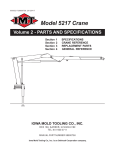
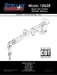
DA440PBT: 99900780: 19990119 i Model DA440PBT PTO, Belt Driven Topdeck Compressor (Previously Model 80 PTO, Blt Driven Topdeck) IOWA MOLD TOOLING CO., INC. BOX 189, 500 HWY 18 WEST, GARNER, IA 50438 TEL: 515-923-3711 TECHNICAL SUPPORT FAX: 515-923-2424 MANUAL PART NUMBER 99900780 DA440PBT: 99900780: 19980224 ii PRECAUTIONS Read before operating your compressor! DANGER EXPLODING TANK WILL CAUSE DEATH, SERIOUS INJURY OR PROPERTY DAMAGE 71393886 ● Drain air tank after each use to prevent moisture build-up and corrosion which leads to tank failure. ● Assure that tank and compressor relief valves work properly, and are at correct pressure settings. ● DO NOT modify or repair air tank. ● NEVER drive vehicle with pressure in air tank. DA440PBT: 99900780: 19990119 iii TABLE OF CONTENTS PARA TITLE PAGE SPARE PARTS LIST iv Section 1. INTRODUCTION 1-1. GENERAL INFORMATION 2. ORDERING INFORMATION 1-111-1 Section 2. INSTALLATION 2-1. GENERAL 2-2. PTO INSTALLATION 2-3. UNDER-DECK COMPRESSOR INSTALLATION 2-1 2-1 2-1 Section 3. OPERATION 3-1. OPERATION 3-2. SYSTEM SHUTDOWN 3-1 3-1 Section 4. PREVENTIVE MAINTENANCE 4-1. PREVENTIVE MAINTENANCE 4-2. LUBRICATION 4-3. PREVENTIVE MAINTENANCE CHECKLIST 4-1 4-1 4-1 Section 5. PARTS 5-1. COMPRESSOR PARTS 5-1 Section 6. REFERENCE LIST OF ILLUSTRATIONS FIGURE TITLE (PART NUMBER) PAGE D-1. TABLE - PREVENTIVE MAINTENANCE CHECKLIST DA440PBT COMPRESSOR-RH, 3/4 TON SGL WHEEL (23000146-1) DA440PBT COMPRESSOR-RH, 3/4 TON SGL WHEEL (23000146-2) INSTALLATION HARDWARE-RH, 3/4 TON, SGL WHEEL DA440PBT COMPRESSOR-LH, 1 TON DUAL WHEEL (23000147-1) DA440PBT COMPRESSOR-LH, 1 TON DUAL WHEEL (23000147-2) DA440PBU COMPRESSOR-CW TRANSMISSION (23000952-1) DA440PBU COMPRESSOR-CW TRANSMISSION (23000952-2) TORQUE DATA CHART TIRE LOAD AND INFLATION PRESSURES 4-1 5-1 5-2 5-3 5-4 5-5 5-6 5-7 6-1 6-2 F-1. F-2. DA440PBT: 99900780: 19980224 iv RECOMMENDED SPARE PARTS LIST 1 Year Supply DA440PBT PTO, BELT DRIVEN TOPDECK COMPRESSOR For Manual: 99900780 This spare parts list does not necessarily indicate that the items can be expected to fail in the course of a year. It is intended to provide the user with a stock of parts sufficient to keep the unit operating with minimal down-time waiting for parts. There may be parts failures not covered by this list. Parts not listed are considered as not being Critical or Normal Wear items during the first year of operations and you need to contact the distributor or manufacturer for availability. ASSEMBLY DESIGNATION 23000146.01.19970624 23000147.01.19961014 ITEM NO. PART NO. DESCRIPTION QTY CODE RH, 3/4 TON, SINGLE WHEEL COMPRESSOR 5 60111268 SHAFT-BELT 18" 6 60118327 SHAFT-BELT 15" 8 70580116 BELT-BP70 9 70580115 BELT-BP33 12 70055062 BEARING-PILLOW BLOCK 24 77041008 PRESSURE SWITCH 31 70048069 AIR FILTER 32 73054031 UNLOADER VALVE 1 1 2 2 4 1 1 1 W W C C C C P C LH, 1 TON, DUAL WHEEL COMPRESSOR 4 70055062 BEARING-PILLOW BLOCK 5 70580126 BELT B84 6 60120068 SHAFT 14 77041008 PRESSURE SWITCH 18 70048069 AIR FILTER 21 73054031 UNLOADER VALVE 2 2 1 1 1 1 C C W C P C 1 1 1 1 1 1 1 1 1 1 1 1 W W W W W W W W P W W C COMPRESSOR (R30)-70073051 REF REF REF REF REF REF REF REF REF REF REF REF 70073727 70073726 70732447 73054340 70073766 70143298 70732429 70732430 70732448 76391490 73054339 73054031 LP INTAKE VALVE LP EXHAUST VALVE HP INTAKE VALVE HP EXHAUST VALVE RING SET RELEASE VALVE KIT INTERCOOLER TUBE LH INTERCOOLER TUBE RH AIR FILTERS SHAFT SEAL POP OFF 70PSI PILOT VALVE SHELF LIFE (MO) ORDER QTY DA440PBT: 99900780: 19941223 1-1 SECTION 1. GENERAL INFORMATION 1-1. INTRODUCTION 1-2. ORDERING INFORMATION This manual provides information on the installation, operation and repair of the IMT DA440PBt PTO, belt driven topdeck compressor. When placing orders or requesting assistance, refer to the information below: Three means are used throughout this manual to gain the attention of operating and service personnel. They are NOTES, CAUTIONS and WARNINGS and are defined as follows: NOTE A NOTE IS USED TO EITHER CONVEY ADDITIONAL INFORMATION OR TO PROVIDE FURTHER EMPHASIS FOR A PREVIOUS POINT. CAUTION A CAUTION IS USED WHEN THERE IS THE STRONG POSSIBILITY OF DAMAGE TO THE EQUIPMENT OR PREMATURE EQUIPMENT FAILURE. WARNING A WARNING IS USED WHEN THERE IS THE POTENTIAL FOR PERSONAL INJURY OR DEATH. Operate this equipment with respect and service it regularly. These two things can add up to a safer working environment and longer equipment life. TO BE COMPLETED BY DEALER CHASSIS INFORMATION TRANSMISSION MAKE: MODEL: PTO NUMBER: PTO %: COMPRESSOR AND HYDRAULIC PUMP INFORMATION COMPRESSOR MODEL: SERIAL NUMBER: PUMP MAKE: MODEL: RESERVOIR CAPACITY: ENGINE RPM: DA440PBT: 99900780: 19941223 1-2 NOTES DA440PBT: 99900780: 19990119 2-1 SECTION 2. INSTALLATION 2-1. GENERAL This section deals with the installation of the PTO. The instructions are intended as a guide to assist you with your particular installation. We can not cover every make, model and year of truck manufactured world-wide, so these instructions will provide only general information. Use this information as a guide only. 2-2. PTO INSTALLATION Power take-off manufacturers provide specific installation instructions for their products. Those instructions should be followed when installing a PTO. Some trucks may require modification of the transmission cross-member to provide clearance and the exhaust pipe may need modification. Check with the PTO manufacturer’s representative for specific instructions regarding your particular make, model and year of vehicle. The following instructions are a guide in this application. 1. If the vehicle is new, drain the transmission oil into a clean container for reuse. If the vehicle is used, drain and dispose of the transmission oil. 2. Temporarily install the PTO with the proper gaskets and only two studs. Snug the PTO down and check the backlash for maximum allowance of 1/32" to 1/16". If the backlash is excessive, remove gaskets and check backlash again until it is corrected. 3. Remove the PTO and apply Permatex to the gaskets. If the holes for the studs are tapped through the transmission housing, apply Permatex to the studs and tighten them down. Make certain that the studs do not interfere with the transmission gears. CAUTION AVOID CONTACT OF PERMATEX WITH AUTOMATIC TRANSMISSION FLUID. 4. Install the PTO and gaskets. Torque the nuts to 30 - 35 ft-lbs (4.14 - 4.84 kg-m) for a 6-bolt PTO and 45 - 50 ft-lbs (6.22 - 6.91 kg-m) for 8-bolt PTO’s. Recheck the backlash. 5. Install the shifter cable to suit conditions. Always allow for a slight overshift on lever or knob to ensure the PTO is fully disengaged. CAUTION IT IS IMPORTANT THAT ADEQUATE SPACE BE ALLOWED FOR FULL ENGAGEMENT OF THE PTO. MODIFY THE EXHAUST OR OTHER OBSTRUCTIONS AS NEEDED. CAUTION AVOID SHARP BENDS IN THE SHIFTER CABLE. ALL BENDS SHOULD HAVE AT LEAST A 6" RADIUS. TIGHTER BENDS WILL CAUSE DIFFICULT OPERATION OF THE SHIFTER KNOB. 6. Replace the transmission oil. If the PTO is located below the transmission oil level, an additional quantity of oil will be required. 7. Start the engine, engage the PTO and allow it to run for 5 - 10 minutes. Check for leaks, unusual noise and proper operation. 8. Retorque the mounting bolts. WARNING THE INSTALLER OF THE DRIVELINE MUST INSPECT THE FINAL POSITION OF THE DRIVELINE TO DETERMINE WHETHER ITS LOCATION PROVIDES SUFFICIENT PROTECTION TO AN OPERATOR, OR OTHER PERSONNEL, FROM HAZARDS ASSOCIATED WITH A ROTATING DRIVELINE. IF PROTECTION IS INSUFFICIENT, THE INSTALLATION OF A GUARD IS REQUIRED. IF YOU ARE UNSURE OF METHODS TO GUARD A ROTATING DRIVELINE, CALL IOWA MOLD TOOLING CO., INC. FOR INSTRUCTIONS. FAILURE TO DO SO MAY RESULT IN SERIOUS INJURY OR DEATH. DA440PBT: 99900780: 19990119 2-3. TOP-DECK COMPRESSOR INSTALLATION Due to the large variety of carrier vehicles, the instructions in this paragraph should be used as a guide only. Refer to Figure E-2 for reference. 1. Position the compressor across the frame of the truck in the desired location. The location selected should provide adequate ventilation while at the same time affording access to the compressor. 2. Lift the compressor base into position. Check for belt clearance and approximate drive shaft length. 3. Using the base as a template, drill four 17/32" diameter holes. The 3/4-ton/RH will be drilled through the top of frame rails. The 1-ton/LH will be drilled through the sides of the frame rails. 4. On the 3/4-ton/LH, insert spacers between base and frame rails. No spacers are used with the 1-ton/ RH. Bolt the compressor base to the frame of the truck using the 1/2" hardware. 5. Using the appropriate driveshaft with knuckles in place, measure the exact length required, cut off excess shaft and weld in place (1/4" weld all around). 6. Install the driveshaft to the PTO and the compressor, tighten the lock bolts and tie-wire in place. 7. Tighten all bolts per Torque Data Chart. 8. Connect the 3/4" air hose from the compressor to the air tank. 9. Install the engine speed control and connect the hoses from compressor to speed control. 2-2 DA440PBT: 99900780: 19950719 3-1 SECTION 3. OPERATION 3-1. OPERATION 3-2. SYSTEM SHUTDOWN This section deals with the proper methods of system operation and shutdown. These procedures should be followed to prevent damage and ensure efficient operation. System shutdown is accomplished as follows: Start the compressor as follows: 1. Ensure the PTO is disengaged and the receiver drain cock is open. 2. Start the truck engine and allow it to idle until it reaches the proper operating temperature (refer to the Owners Manual). 3. Depress the clutch, engage the PTO and carefully release the clutch pedal. 4. Activate the engine speed control by closing the receiver drain cock. The compressor is now operating and supplying working air. NOTE WHEN STARTING THE COMPRESSOR, THE RPM’S WILL AUTOMATICALLY INCREASE DUE TO LOW VOLUME OF AIR IN THE SYSTEM CAUTION 1000 RPM MAX. Operating this unit in excess of 1000 RPM, measured at the compressor flywheel, will void your warranty. Engine RPM may be different. 1. Allow the compressor to build to maximum pressure and the truck engine will automatically idle down. 2. Place the compressor control valve in the open (off) position. 3. Depress the clutch pedal and disengage the PTO. 4. Open the receiver drain cock and discharge the air in the receiver. WARNING FEDERAL LAW PROHIBITS DRIVING THE CARRIER VEHICLE ON PUBLIC ROADS WITH THE RECEIVER FILLED WITH COMPRESSED AIR. ALWAYS DRAIN THE RECEIVER BEFORE MOVING THE VEHICLE. DA440PBT: 99900780: 19950719 3-2 NOTES DA440PBT: 99900780: 19941223 4-1 Section 4. PREVENTIVE MAINTENANCE 4-1. PREVENTIVE MAINTENANCE Proper maintenance on a regular schedule is essential to keep your unit operating efficiently. Proper maintenance procedures and required service intervals are outlined in this section. Personnel responsible for unit upkeep should become familiar with frequency and type of maintenance required and perform these tasks at recommended intervals. 4-2. LUBRICATION The only lubrication required is on the carrier vehicle and the compressor itself. Refer to the appropriate Owners Manual for information on the truck and compressor for the type and frequency of lubrication required. CAUTION USE ONLY A 30W NON-DETERGENT OIL IN THE COMPRESSOR. DO NOT USE A SYNTHETIC OIL. 4-3. PREVENTIVE MAINTENANCE CHECKLIST The checklist (Figure A) is designed to assist you in keeping your unit in efficient operating condition. Items in this section apply to the unit only. The carrier vehicle should also be inspected regularly (refer to the carrier vehicles service manual). FIGURE A. PREVENTIVE MAINTENANCE CHECKLIST DA440PBT: 99900780: 19941223 4-2 DA440PBT: 23000146.01.19970624 5-1 SECTION 5. PARTS 5-1. COMPRESSOR PARTS This section contains the exploded parts drawings with accompanying parts lists for associated assemblies. These drawings are intended to be used in conjunction with the instructions found elsewhere in this manual. For information pertaining to the compressor, refer to its specific manual. ITEM PART NO. DESCRIPTION 1. 2. 3. 4. 5. 6. 7. 8. 9. 10. 11. 12. 13. 14. 15. 16. BASE WELDMENT BEARING BRACKET TIGHTENER BOLT 4" SCREW-BELT TIGHTENER SHAFT-BELT 18" SHAFT-BELT 15" COMPRESSOR-R30 BELT-BP70 GATES 9003-2070 BELT-BP33 GATES 9003-2033 PULLEY SHEAVE 4" 2-GROOVE BEARING-PILLOW BLOCK BUSHING CARR BOLT 1/2-13X2 SQNK GR2 CAP SCR 1/2-13X1-3/4 HHGR5 CAP SCR 1/2-13X2 HHGR5 52712404 52712567 52706205 52704923 60111268 60118327 70073051 70580116 70580115 70056272 70056388 70055062 70143234 72060957 72060094 72060095 QTY 1 1 2 1 1 1 1 2 2 2 1 4 1 4 4 4 ITEM PART NO. DESCRIPTION QTY 17. 18. 19. 20. 21. 22. 23. 24. 27. 28. 29. 31. 32. 33. 34. 35. NUT 3/4-10 HEX NUT 1/2-13 LOCK WASHER 1/2 WRT PIPE NIPPLE 1/4NPT X CLOSE STREET TEE 1/4NPT BRS PIPE PLUG 1/8NPT SQHD STREET ELBOW 1/4NPT 45° PRESSURE SWITCH HOSE FITTING 1/4 1/4 STREET ELBOW 1/4NPT 90° SHT CARR BOLT 3/8-16X2 SQNK GR2 AIR FILTER UNLOADER VALVE PIPE PLUG 1/4NPT BUSHING-SPLIT TAPER GREASE ZERK 1/8NPT 90° 2 16 12 1 1 1 1 1 1 1 4 1 1REF 1 2 2 72062007 72062080 72063005 72053013 72532013 72053411 72053533 77041008 72532552 72532974 72601430 70048069 73054031 72053245 70056116 72035361 DA440PBT COMPRESSOR-RH, 3/4 TON, SINGLE WHEEL (23000146-1) DA440PBT: 23000146.02.19960723 5-2 DA440PBT COMPRESSOR-RH, 3/4 TON, SINGLE WHEEL (23000146-2) DA440PBT: 19941223 ITEM PART NO. 1. 2. 3. 4. 72060095 72063005 60113720 72062080 DESCRIPTION CAP SCR 1/2-13X3 HHGR5 WASHER 1/2 WRT SPACER NUT 1/2 LOCK 5-3 QTY 4 8 4 4 INSTALLATION HARDWARE-RH, 3/4 TON, SINGLE WHEEL DA440PBT: 23000147.01.19961014 ITEM PART NO. DESCRIPTION 1. 2. 3. 4. 5. 6. 7. 8. 9. 10. 11. 12. 13. FRAME WELDMENT-LH COMPRESSOR TIGHTENER BOLT 4" BEARING-PILLOW BLOCK BELT-B84 GATES 9093-2083 SHAFT 1-1/4 X 10-1/4 BUSHING PULLEY DUAL GROOVE 9" CAP SCR 1/2-13X5-1/2 HHGR5 NUT 1/2-13 LOCK WASHER 1/2 WRT STREET ELBOW 1/4NPT 90° SHT PIPE NIPPLE 1/4NPT X CLOSE 52713749 70073051 52706205 70055062 70580126 60120068 70056111 70056523 72060102 72062080 72063005 72532974 72053013 5-4 QTY 1 1 2 2 2 1 1 1 2 4 4 1 1 ITEM PART NO. DESCRIPTION 14. 15. 18. 19. 21. 22. 23. 24. 25. 26. 27. 28. 29. PRESSURE SWITCH HOSE FITTING 1/4 1/4 AIR FILTER STREET TEE 1/4NPT BRS UNLOADER VALVE PIPE PLUG 1/8NPT SQHD STREET ELBOW 1/4NPT 45° PIPE PLUG 1/4NPT CAP SCR 1/2-13X1-1/2 HHGR5 WASHER 1/2 WRT NUT 1/2-13 LOCK CAP SCR 1/2-13X6 HHGR5 SUPPORT 77041008 72532552 70048069 72532013 73054031 72053411 72053533 72053245 72060093 72063005 72062080 72060108 60118856 DA440PBT COMPRESSOR-LH, 1 TON, DUAL WHEEL (23000147-1) QTY 1 1 1 1 1REF 1 1 1 4 4 4 2 1 DA440PBT: 23000147.02.19961014 5-5 DA440PBT COMPRESSOR-LH, 1 TON, DUAL WHEEL (23000147-2) DA440PBT: 19990119 5-6 DA440PBT:99900780: 19941223 6-1 SECTION 6. REFERENCE When using the torque data in the charts above, the following rules should be observed. 1. Bolt manufacturers particular specifications should be consulted when provided. 2. Flat washers of equal strength must be used. 3. All torque measurements are given in foot-pounds. To convert to inch-pounds, multiply by 12. 4. Torque values specified are for bolts with residual oils or no special lubricants applied. If special lubricants of high stress ability, such as Never-Seez compound graphite and oil, molybdenum disulphite, collodial copper or white lead are applied, multiply the torque values in the charts by the factor .90. The use of Loctite does not affect the torque values listed above. 5. Torque values for socket-head capscrews are the same as for Grade 8 capscrews. FIGURE F-1. TORQUE DATA CHART DA440PBT:99900780: 19941223 6-2 FIGURE F-2. TIRE LOAD AND INFLATION PRESSURES DA440PBT:99900780: 6-3 DA440PBT:99900780: 6-4 LIMITED WARRANTY WARRANTY COVERAGE - Products manufactured by Iowa Mold Tooling Co., Inc. (IMT) are warranted to be free from defects in material and workmanship, under proper use, application and maintenance in accordance with IMTs written recommendations, instructions and specifications as follows: WARRANTY VOIDED - All obligations of IMT under this warranty shall be terminated:(1) if service other than normal maintenance or normal replacement of service items is performed by someone other than an authorized IMT dealer, (2) if product is modified or altered in ways not approved by IMT. 1. Ninety (90) days; labor on IMT workmanship from the date of shipment to the end user. PURCHASERS RESPONSIBILITY - This warranty covers only defective material and workmanship. It does not cover depreciation or damage caused by normal wear, accident, improper protection in storage, or improper use. The purchaser has the obligation of performing the care and maintenance duties discussed in IMTs written recommendations, instructions and specifications. Any damage which results because of purchasers failure to perform such duties shall not be covered by this warranty. The cost of normal maintenance and normal replacement of service items such as filters, belts, etc. shall be paid by the purchaser. 2. One (1) year; original IMT parts from the date of shipment to the end user. IMTs obligation under this warranty is limited to, and the sole remedy for any such defect shall be the repair or replacement (at IMTs option) of unaltered parts returned to IMT, freight prepaid, and proven to have such defect, provided such defect occurs within the above stated warranty period and is reported within fourteen (14) days of its occurence. IMPLIED WARRANTY EXCLUDED - This is the only authorized IMT warranty and is in lieu of all other express or implied warranties or representations, including any implied warranties of merchantability or fitness for any particular purpose or of any other obligations on the part of IMT. ITEMS EXCLUDED - The manufacturer gives no warranty on any components purchased by the manufacturer, and such components as are covered only by the warranties of their respective manufacturers. WARRANTY CLAIMS - Warranty claims must be submitted and shall be processed in accordance with IMTs established warranty claim procedure. WARRANTY SERVICE - Warranty service will be performed by any IMT distributor authorized to sell new IMT products of the type involved or by any IMT Service Center authorized to service the type of product involved or by IMT in the event of direct sales made by IMT. At the time of requesting warranty service, the purchaser must present evidence of the date of delivery of the product. The purchaser shall pay any premium for overtime labor requested by the purchaser, any charge for making service calls and for transporting the equipment to the place where warranty work is performed. CONSEQUENTIAL DAMAGES - The only remedies the purchaser has in connection with the breach or performance of any warranty on IMT products are those set forth above. In no event will the dealer, IMT or any company affiliated with IMT, be liable for business interruptions, loss of sales and/or profits, rental or substitute equipment, costs of delay or for any other special, indirect, incidental or consequential losses, costs or damages. REPRESENTATIONS EXCLUDED - IMT products are subject to no expressed, implied or statutory warranty other than herein set forth, and no agent, representative or distributor of the manufacturer has any authority to alter the terms of this warranty in any way whatsoever or to make any representations or promises, express or implied, as to the quality or performance of IMT products other than those set forth above. CHANGE IN DESIGN - IMT reserves the right to make changes in design or improvements upon its products without imposing any obligation upon itself to install the same upon its products theretofore manufactured. Effective January, 1985 This parts manual is provided to the user to assist in servicing the equipment. It is the propertyof Iowa Mold Tooling Co., Inc and, as such, may not be reproduced either whole or in part,whether by chemical, electrostatic, mechanical or photographic means without the expressedwritten permission of an officer of Iowa Mold Tooling Co., Inc. One manual is provided with each piece of new equipment and additional manuals may be obtained at a nominal price. IOWA MOLD TOOLING CO., INC. BOX 189, GARNER, IA 50438-0189 TEL: 515-923-3711 TECHNICAL SUPPORT FAX: 515-923-2424