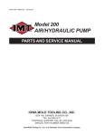
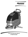
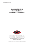
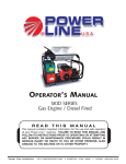
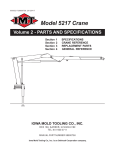
1
TRPR:99900388: 20070329
Parts and Service Manual
TIREPUMPER
IOWA MOLD TOOLING CO., INC.
BOX 189, GARNER, IA 50438-0189
TEL: 641-923-3711
TECHNICAL SUPPORT FAX: 641-923-2424
MANUAL PART NUMBER 99900388
Iowa Mold Tooling Co., Inc. is an Oshkosh Truck Corporation company.
TRPR:99900388:
--------
REVISIONS LIST
DATE
20070329
LOCATION
COVER
DESCRIPTION OF CHANGE
UPDATED OWNERSHIP STATEMENT
TRPR:99900388:
20000801
NOTES
TRPR:99900388: 19951215
TABLE OF CONTENTS
PARAGRAPH
TITLE
PAGE
Section 1. OPERATION
1-1.
Principle of Operation ........................................................................................... 1-1
1-2.
Operation .............................................................................................................. 1-1
1-3.
Mixing Solution ..................................................................................................... 1-1
1-4.
Connecting the Valve Stem .................................................................................. 1-2
1-5.
Removing Solution from Tires .............................................................................. 1-2
1-6.
Filling Tires ........................................................................................................... 1-3
1-7.
Liquid Weighting of Tractor Tires ........................................................................... 1-4
Section 2. INSTALLATION AND REPAIR
2-1.
Installation Procedure ........................................................................................... 2-1
2-2.
Air Supply ............................................................................................................. 2-1
2-3.
Freezing or Icing of Exhaust ................................................................................. 2-1
2-4.
Maintenance ......................................................................................................... 2-1
2-5.
Check Valve Servicing .......................................................................................... 2-1
2-6.
Pump Servicing .................................................................................................... 2-1
2-7.
Troubleshooting .................................................................................................... 2-2
2-8.
Recommended Lubricants .................................................................................... 2-2
Section 3. PARTS
3-1.
General ................................................................................................................. 3-1
LIST OF ILLUSTRATIONS
FIGURE
TITLE
A-1.
A-2.
C-1.
C-2.
C-3.
C-4.
Connecting 2-piece Valve Stem............................................................................ 1-2
Connecting 1-piece Valve Stem............................................................................ 1-2
Tirepumper Assembly (51709670) ....................................................................... 3-1
4-way Valve Assembly (70732360) ...................................................................... 3-2
Option - Air Inflation Kit (51709763) ...................................................................... 3-3
Option - Calcium Chloride Inflator (70731567) ..................................................... 3-4
PAGE
LIST OF TABLES
TABLE
TITLE
A-1.
A-2.
Liquid Weighting - Front Tractor Tires .................................................................... 1-4
Liquid Weighting - Rear Tractor Tires .................................................................... 1-5
PAGE
TRPR:99900388: 19951215
1-1
SECTION 1. OPERATION
1-1. PRINCIPLE OF OPERATION
The TIREPUMPER is a two-chambered pump
driven by compressed air against a diaphragm. Each
chamber is divided by a diaphragm. One side of the
diaphragm is the liquid being pumped. As compressed air moves one diaphragm outward, the
diaphragm in the other chamber is drawn inward by
a reciprocating rod which connects the two diaphragms. As the diaphragm moves outward, it
causes pressure on the liquid side of the diaphragm
which evacuates that chamber. Simultaneously, the
other diaphragm is creating a vacuum on the liquid
side of the diaphragm which draws liquid into the
other chamber. At the end of the stroke, the rod and
diaphragms change direction and the chamber that
just filled is evacuated. As one chamber fills, the
other chamber evacuates and then the rod reverses
direction. The two fluid chambers are manifolded
together with a suction and discharge check valve
for each chamber to maintain flow in one direction.
Alternate pressurizing and exhausting of the diaphragm air chamber is performed by an air distribution valve. When the spool is at one end of the valve
body, inlet air pressure is connected to one diaphragm chamber and the other diaphragm air
chamber is connected to the exhaust. When the
spool moves to the opposite end of the valve body,
the chamber porting is reversed.
1-2. OPERATION
A. The Tirepumper does not come standard with a
built-in lubrication reservoir. An in-line lubricator
should be installed in the compressed air line and
filled with Air Lube AF anti-freeze lubricant for year
around operation. No alterations should be made to
the pump.
B. Make sure air line to pump is free from dirt or
other foreign matter. Blow out air line before
attaching to pump.
C. Turn on air supply to pump.
CAUTION
MAKE SURE AIR SUPPLY PRESSURE TO PUMP
DOES NOT EXCEED 125 PSIG.
The Tirepumper is supplied with a preset pressure
regulator. Do not attempt to alter regulator knob or
breakage will occur.
Pumping volume is controlled by a color flow valve
which is supplied.
D. Pumping volume (gpm) can be set by counting
the number of strokes per minute. The Tirepumper
pumps approximately 1/10 gallon per stroke. A
stroke is 1/2 cycle or one air exhaust.
When pump is used for moving thick materials check
stroke rate to determine that pump is not operating at
a faster rate than material is capable of flowing, or
cavitation will occur. If pump is operating at a speed
too fast for available flow, reduce the volume of air
to the pump until stroke rate approximates discharge
volume (30-60 cycles per minute).
If opening the color flow valve increases cycling rate
without increasing the flow rate, the pump is being
starved of liquid due to suction limitations. Further
opening of the air inlet valve will waste compressed
air. Set the inlet valve for the lowest
cycling rate
that meets your particular needs.
1-3. MIXING SOLUTION
Prepare by pouring the calcium chloride mixture into
the water (never the water into the calcium chloride,
as considerable heat is generated in this mixing
process). The solution should be allowed to cool to
atmospheric temperature before pumping in the tire.
TRPR:99900388: 19951215
1-4. CONNECTING THE VALVE STEM
The following connections should be made when the
pump is not running and with control handle in the
check position. To connect liquid fill core ejector to
2-piece style rear tractor valves (see Figure A-1):
1-2
To connect liquid fill core ejector to 1-piece style
front tractor valves (see Figure A-2):
1. Screw adapter (item A) and gasket to union
(item 1).
1. Unscrew union (item 1) from core ejector body
(item 2) and screw on valve stem finger tight.
2. Insert large end of core remover (item B)
securely into chuck of core housing ejector (item 6).
2. Screw core ejector body on union (item 1)
making certain rubber gasket (item 3) is in place,
with handle (item 4) of core ejector pulled out.
3. Screw adapter and union assembly n valve stem
finger tight.
3. Push handle (item 4) of core ejector in until it
makes contact with the core housing of the valve,
then hold the core ejector in left hand, strike the
handle (item 4) with the right hand to force the core
housing in ejector chuck (item 6).
4. Turn handle (item 4) to the left to unscrew the
core housing, pushing inward lightly so you can feel
the threads disengage when completely unscrewed.
5. Pull handle (item 4) out as far as it will go to
retract core housing into ejector body. The handle
will pull out easier if rotated while pulling, as packing
nut (item 7) should be tight enough to prevent air or
liquid leaks.
4. Screw ejector union and adapter assembly to
core ejector body making sure gasket is in place.
The rest of the operation is the same as with the
above 2-piece valve as described above.
1-5. REMOVING SOLUTION FROM TUBETYPE OR TUBELESS TIRE
Jack up tractor until tire is slightly deflected and
valve is at the bottom. Connect core housing ejector
and union to valve stem as previously described.
Unscrew and retract core housing into ejector body
with control handle at check position.
Turn control handle to evacuate position and start
pump. Run until tire is completely evacuated. Turn
control handle to check position, stop pump and
disconnect core ejector after replacing core housing
in valve stem.
In case of a tubeless tire, unseat beads and demount
front bead from rim and pump remaining solution
from tire.
FIGURE A-1.
FIGURE A-2.
TRPR:99900388: 19951215
1-6. FILLING TUBE-TYPE OR TUBELESS
TIRES WITH SOLUTION
1-3
To fill a tire 75% with water or solution:
7. Replace core housing in valve stem by pushing
handle in until contact is made and turn to right until
core housing is screwed tight in valve stem.
1. Inflate tire to 35 psi after beads have been fully
seated in mounting procedure.
8. Withdraw handle, turn handle to evacuate, and
pump all liquid from hose.
2. Jack up the wheel, if done on a tractor, and turn
to bring valve to top position.
9. Shut off pump, then unscrew ejector body (item
2) and union (item 1) from valve.
3. Lower jack until tire is slightly deflected.
10. Set final working pressure after tire has been
mounted on tractor with weight on tire and valve at
bottom, using anair-water gauge according to tire
manufacturer’s specifications.
4. With pump not running and control handle at
check position, connect ejector and remove core
housing as described above.
5. After connection is made, bleed pressure down
to about 5 lbs. (to keep the beads seated on the rim)
by moving control handle to evacuate position.
6. Start pump and move control handle to fill
position. Start hydroinflating tire. Check pressure in
tire every few minutes with pump gauge by placing
pump in the check position. If pressure exceeds 20
psi move handle to evacuate until pressure is bled
back to not less than 5 psi. After pressure is lowered, continue pumping. Repeat above steps as
often as necessary to fill until water or solution
weight added to the assembly is equal to that shown
in the Liquid Weighting Tables.
WARNING
NEVER INFLATE BEYOND 35 LBS. PRESSURE. IF
BEADS HAVE NOT SEATED BY THE TIME
PRESSURE REACHES 35 PSI, DEFLATE THE
ASSEMBLY, REPOSITION THE TIRE ON THE RIM,
RE-LUBRICATE AND RE-INFLATE. AFTER
SEATING BEADS, ADJUST INFLATION TO
RECOMMENDED PRESSURE. ALLOWING AIR
PRESSURE TO BUILD WITHIN THE ASSEMBLY IN
AN ATTEMPT TO SEAT THE BEADS IS A
DANGEROUS PRACTICE. IN SEATING BEADS,
INFLATION BEYOND 35 POUNDS PRESSURE MAY
BREAK THE BEAD (OR EVEN THE RIM) WITH
EXPLOSIVE FORCE SUFFICIENT TO CAUSE
SERIOUS PHYSICAL INJURY OR DEATH. INSPECT
BOTH SIDES OF THE TIRE TO BE SURE BEADS
ARE EVENLY SEATED. IF NOT, COMPLETELY
DEFLATE TIRE, UNSEAT BEADS AND REPEAT
ENTIRE MOUNTING PROCEDURE.
TRPR:99900388: 19951215
1-7. LIQUID WEIGHTING OF TRACTOR
TIRES
The following tables provide data on the filling of
front and rear tractor tires with calcium chloride
solution, based on valve level or approximately 75%
fill.
These tables are based on the use of Type 1 - 77%
commercial calcium chloride flake. If Type 2 - 94%
calcium chloride flake is used, reduce the pounds/
kilograms CaCl2 weights in these tables by 25%.
1-4
Where freezing temperatures never occur, plain
water can be used, but the weight added will be 20%
less than calcium chloride solution. Plain water
freezes solid at 32°F/0°C.
Where anti-freeze protection is needed, the 3-1/2 lb/
420g calcium chloride solution is slush free to -12°F/24°C and will freeze solid at -52°F/-47°C. The 5 lb/
600g calcium chloride solution is slush free to -52°F/47°C and will freeze solid at -62°F/-52°C.
TRPR:99900388: 19910615
1-5
TRPR:99900388: 19910615
1-6
TRPR:99900388: 19951215
2-1
SECTION 2. INSTALLATION AND REPAIR
WARNING
POSSIBLE EXPLOSION HAZARD CAN RESULT IF
1,1,1,-TRICHLOROETHANE, METHYLENE
CHLORIDE OR OTHER HALOGENATED
HYDROCARBON SOLVENTS ARE USED IN
PRESSURIZED FLUID SYSTEMS HAVING
ALUMINUM OR GALVANIZED WETTED PARTS.
DEATH, SERIOUS BODILY INJURY OR PROPERTY
DAMAGE COULD RESULT. CONSULT WITH THE
FACTORY IF YOU HAVE QUESTIONS
CONCERNING THE USE OF HALOGENATED
HYDROCARBON SOLVENTS.
2-1. INSTALLATION PROCEDURE
Position the pump as close as possible to the source
of the liquid to be pumped. Avoid long or undersized
suction lines and use as few fittings as necessary. At
the time of installation, inspect all external fasteners
for tightness. Tighten loose fittings to prevent
leakage.
The pump can be submerged if the materials of
construction are compatible with the liquid and the
exhaust is piped above the liquid level. Piping for the
exhaust must not be smaller than 1". Reduced pipe
size can restrict the exhausted air and reduce pump
performance.
If the unit is to be totally submerged, the air exhaust
must be piped above liquid level to prevent the liquid
and foreign material from entering the air distribution
mechanism.
2-2. AIR SUPPLY
Do not connect the unit to an air supply in excess of
125 PSI (8.61 bar). Install a shutoff valve in the air
line to permit removal of the pump for servicing.
When connecting an air supply of rigid piping, mount
a section of flexible line to the pump to eliminate
strain on the piping. The use of an in-line air filter is
recommended. Support the weight of the air line and
filter to prevent excessive weight on the pump’s air
valve. Failure to comply may result in damage to the
pump.
2-3. FREEZING OR ICING OF EXHAUST
Icing of the air exhaust can occur under certain
conditions. When pump performance suffers
because of icing, be certain to use the proper lubricant as shown in the Troubleshooting section. Icing
is more likely to occur at high discharge pressures.
2-4. MAINTENANCE
CAUTION
BEFORE MAINTENANCE OR REPAIR, SHUT OFF
THE COMPRESSED AIR, BLEED THE PRESSURE
AND DISCONNECT THE AIR LINE FROM THE
PUMP. THE PUMP DISCHARGE LINE MAY BE
PRESSURIZED AND MUST BE BLED. WHEN THE
PUMP IS USED FOR TOXIC OR CAUSTIC FLUIDS,
IT SHOULD BE FLUSHED CLEAN PRIOR TO
DISASSEMBLY.
When the pump is used for materials that tend to
settle out or change state from a liquid to a solid,
care must be taken after each use or during idle time
to remove them and flush the pump as required to
prevent damage.
In freezing temperatures, the pump must be completely drained unless the liquid is resistant to freezing. After disconnecting the discharge and inlet
hoses, tilt the pump to drain the fluid.
2-5. CHECK VALVE SERVICING
The need for servicing is usually indicated by poor
priming, unstable cycling, poor performance or the
pump is cycling, but not pumping.
Remove the manifold. Inspect the balls and seats for
wear or damage. If pump is to prime properly,
valves must be air tight.
2-6. PUMP SERVICING
Refer to the “Disassembly/Reassembly Instructions”
(manual part numbrer 99900503) for any repair
procedures specific to the pump (IMT part number
70731387).
CAUTION
WEAR SAFETY GLASSES WHENEVER REPAIRS
ARE BEING PERFORMED. FAILURE TO DO SO CAN
RESULT IN SERIOUS INJURY.
TRPR:99900388: 19951215
2-7. TROUBLESHOOTING
This information is to be used as a guide to help you
determine a plan of action when experiencing one or
more of the following conditions. This guide should
be used in conjuction with appropriate manuals which
accompany the Tirepumper. The following conditions of operation are covered in this guide:
1. Fast Cycles/Low Volume
2. No Cycles
3. Leaking
4. Noise
5. Parts Breakage
6. Slow Cycles
7. Erratic Cycles
These are all common conditions that may be
experienced over the life of your pump. Each
condition is broken down into potential causes. The
causes are listed, and recommendations to correct
these causes are given.
Definitions for specific terms used within this guide
are listed below:
AIR VALVE - Brass or stainless steel housing
attached to the pump center block by four bolts.
PISTON - Aluminum cylinder housing within the air
valve. Controls flow of air within the pump.
CAVITATION - Pump is discharging less fluid than
its rated capacity due to a reduction or lack of fluid
supply to the pump inlet. In effect, the pump’s liquid
chamber is not filled prior to discharge.
STATIC DISCHARGE HEAD - The vertical
distance, in feet, from the pump center line to the
point of free delivery of the liquid.
2-2
INLET PRESSURES - Includes the relative weight
and velocity of the fluid measured in pounds of
pressure at the inlet of the pump.
SPECIFIC GRAVITY - Ratio of any liquid’s weight
to that of water at 62°F. Water at 62°F is said to
have a specific gavity of 1.0.
STATIC SUCTION LIFT - The vertical distance, in
feet, from the liquid supply level to the pump centter
line, the pump being above supply level.
VAPOR PRESSURE - All liquids exert pressure due
to formatrion of vapor at its free surface. In any
pumping system the pressure at any point should
never be reduced below the vapor pressure of the
liquid or vapor will form causing partial or complete
stoppage of liquid flow into the pump.
VISCOSITY - That property which offers resistance
to flow due to the existence of internal internal
friction within the fluid.
WATER HAMMER - The internal effects on the
pump of forces placed on it by high inlet pressures or
static head pressures.
2-8. RECOMMENDED LUBRICANTS
The use of Air Lube AF anti-freeze lubricant is
recommended (IMT Part # 89086160-QT, 89086161GAL). The following 5 WT, grade 15 lubricants may
be used if performance does not suffer:
EXXON - Univis N Grade 15
MOBIL - DTE 11M
PENZOIL - Penzbell AWX Arctic Wt Hyd Oil
SHELL - Tellus T 15 Oil
TEXACO - Code 1693 Rando Oil HD 2-15 HVI
TRPR:99900388: 19951215
2-3
TRPR:99900388: 19951215
2-4
TRPR:99900388: 19970106
3-1
SECTION 3. PARTS
3-1. GENERAL
This section is provided as an aid in the identification,
repair and ordering of parts. See the “Disassembly/
Reassembly Instructions” manual for component
parts specific to the pump (IMT part number
70731387).
ITEM PART NO.
DESCRIPTION
1.
2.
3.
4.
5.
6.
7.
8.
9.
10.
11.
12.
13.
14.
15.
PUMP
VALVE ASM - 4 WAY
ADAPTER 3/4MPT 3/4MPT
TEE 3/4NPT
RED. BUSHING 3/4 3/4NPT
VACUUM GAUGE
ELBOW 3/4MPT 1-5/16MJIC 90°
TUBE ASM
ELBOW 1"MPT 1-5/16MJIC 90°
COUPLING 1"NPT STL
PIPE NIPPLE 1/4NPT X CLOSE
STREET ELBOW 1/4NPT 90°
AIR REGULATOR
PIPE PLUG 1/8NPT HOL HEX
HOSE FITTING 1/4 1/4 TYPE O
70731387
70732360
72053558
72053555
72531831
70048011
72531429
70143793
72531430
72053473
72053013
72531131
70048059
72053240
72532552
QTY
1
1
1
1
1
1
1
1
1
1
2
2
1
1
4
ITEM PART NO.
DESCRIPTION
16.
17.
18.
19.
20.
21.
22.
23.
24.
25.
26.
27.
28.
29.
30.
HOSE 1/4 PUSH LOCK
34"
COLOR-FLOW VALVE
1
MTG BRACKET - AIR CTRL
2
DECAL
1
MOUNTING PLATE
1
CAP SCR 5/16-18X1 HHGR5
3
NUT 5/16-18 LOCK
4
WASHER 5/16 WRT
4
MACH SCR #10-24X3/4 RDHD
4
NUT #10-24 LOCK
4
RUBBER BUMPER
4
DECAL-LUBRICATE PUMP
1
VALVE-SHUTOFF
1
TEE 1/4NPT STL
1
CAP SCR 5/16-18X1-1/4 HHGR5 1
89392146
73054034
52709397
70393263
60113887
72060025
72062109
72063002
72060636
72062106
76039990
70392497
73054108
72053610
72060026
FIGURE C-1. TIREPUMPER ASSEMBLY (51709670)
QTY
TRPR:99900388: 19910615
ITEM PART NO.
DESCRIPTION
1.
2.
3.
4.
5.
6.
7.
8.
9.
10.
11.
12.
13.
14.
15.
BODY
ROTOR 3/4 BRASS
CAP
HANDLE
WASHER 1/4 WRT
CAP SCR 1/4-20X1/2 HH GR5
CAP SCR 1/4-20X5/8 HH GR5
SEAL-PORTED (PART OF 15)
O-RING (PART OF 15)
O-RING (PART OF 15)
WASHER-BTM(PART OF 15)
WASHER-TOP(PART OF 15)
O-RING (PART OF 15)
O-RING (PART OF 15)
REPAIR KIT (INCL:8-14)
70143877
77041434
70143878
70143879
72063001
72062000
72060001
76393362
76393365
76393364
70143881
70143880
76393366
76393363
51393264
3-2
QTY
1
1
1
1
1
1
4
4REF
1REF
1REF
1REF
1REF
1REF
4REF
1
FIGURE C-2. 4-WAY VALVE ASSEMBLY (70732360)
TRPR:99900388: 19960925
3-3
ITEM PART NO.
DESCRIPTION
1.
2.
3.
4.
5.
6.
7.
8.
9.
10.
11.
12.
ADAPTER 1/2MPT X 1/2MPT
1
BARB NIPPLE 1/2MPTX1/2BARB 2
TEE 3/5NPT
1
ADAPTER 3/4MPT X 3/4MPT
1
ST ELBOW 1/2NPT BRS 90°
1
TEE 1/2NPT BRS
1
ADAPTER 3/4MPT 1/2MPT HEX 1
HOSE CLAMP SAE#12
2
BALL VALVE 1/2NPT
1
IN-LINE CHECK VALVE 1/2FPT
1
AIR HOSE 1/2 RED 250PSI
24"
ST ELBOW 1/4NPT BRS 90°
1
72053725
72053457
72053555
72053558
72053591
72531961
72053726
72066004
73054192
73054676
89039176
72053523
QTY
FIGURE C-3. OPTION - AIR INFLATION KIT (51709763)
TRPR:99900388: 19910615
3-4
TO OPERATE:
1. Position wheel so valve is at top.
2. Remove valve cap and loosen valve core housing before
attaching inflator to valve.
NOTE
To service standard bore valves, assemble nose adapter to
inflator. This adapter has a rubber gasket for sealing against
rim nut.
Do not use nose adapter when servicing super large bore
valves TR F900, TR F910, TR F910B and TR F916.
Connect inflator to valve mouth and rotate knurled swivel nut to
engage threads. Tighten nut until valve hits stop in inflator.
Tighten by hand only!
3. Engage knurls on core housing with collet by pushing knob
forward and tapping lightly with hand.
4. Turn knob counterclockwise to remove core housing from
valve.
5. Retract knob assembly completely to rear of inflator to
disengage core housing.
6. Start liquid filling. When tire appears to be fully inflated,
rotate the valve handle to the CHECK position to bleed
trapped air from the tire. Continue filling in this manner until
the tire is properly filled.
7. Shut off pump. Insert core housing into valve stem by pushing
knob assembly forward and turning clockwise until the core is
fully engaged.
8. Disengage collet from core housing by pulling knob assembly
firmly toward the rear of the inflator.
9. Unscrew the inflator from the valve stem.
10. Tighten the valve core securely.
11. Check the tire pressure and top-off as necessary.Use standard
air gauge and chuck.
ITEM PART NO.
DESCRIPTION
1.
2.
3.
4.
5.
6.
7.
8.
9.
10.
11.
12.
13.
14.
15.
16.
17.
18.
19.
20.
21.
22.
76392292
70024285
7Q072016
70024286
76392293
76392294
70024287
70142699
72066618
70142700
7Q072014
70024288
7Q072011
70024289
72066618
70024290
7Q072006
70024291
70024323
76392421
70142864
51392295
23.
24.
25.
26.
70024307
70024321
70731625
70024322
RUBBER WASHER 13/16
1
ADAPTER-TRACTOR & LG BORE 1
O-RING (PART OF 4)
1
INFLATOR SUB-ASM(INCL:3,5-7) 1
RUBBER WSHR 3/4(PART OF 4) 1
LENS (PART OF 4)
1
SOCKET NUT (PART OF 4)
1
COLLET (PART OF 25)
1
LOCK PIN (PART OF 25)
1
ROD (PART OF 25)
1
O-RING (PART OF 25)
1
HOUSING CAP (PART OF 25)
1
O-RING (PART OF 25)
1
O-RING RETAINER(PART OF 25) 1
LOCK PIN (PART OF 25)
1
KNOB (PART OF 25)
1
O-RING
1
PLUG
1
ADAPTER-STD TIRE VALVE
1
RUBBER WASHER 3/4
1
CORE EXTRACTOR
1
REPAIR KIT
(INCL:1,3,9,13,15,17,20)
REF
ADPTER W/WASHER(INCL:1&2) REF
PLUG W/O O-RING(INCL:17&18) REF
KIT (INCL:8-16)
REF
ADAPTER W/WASHER
(INCL:19 & 20)
REF
EXTRACTOR KIT(INCL:19,20,21)REF
27. 70731694
FIGURE C-4. OPTION - CALCIUM CHLORIDE TIRE INFLATOR (70731567)
QTY
TRPR:99900388: 19910615
TRPR:99900388: 20000707
This parts manual is provided to the user to assist in servicing the equipment. It is the propertyof Iowa Mold Tooling Co., Inc and, as
such, may not be reproduced either whole or in part,whether by chemical, electrostatic, mechanical or photographic means without the
expressedwritten permission of an officer of Iowa Mold Tooling Co., Inc. One manual is provided with each piece of new equipment and
additional manuals may be obtained at a nominal price.
IOWA MOLD TOOLING CO., INC.
BOX 189, GARNER, IA 50438-0189
TEL: 641-923-3711
TECHNICAL SUPPORT FAX: 641-923-2424