1
Label PRINTER
TSP828L SERIES
Hardware Manual
Federal Communications Commission
Radio Frequency Interference
Statement
This equipment has been tested and found to comply with the limits for a Class A digital device, pursuant to Part 15
of the FCC Rules. These limits are designed to provide reasonable protection against harmful interference when the
equipment is operated in a commercial environment. This equipment generates, uses and can radiate radio frequency
energy and, if not installed and used in accordance with the instruction manual, may cause harmful interference to
radio communications. Operation of this equipment in a residential area is likely to cause harmful interference in
which case the user will be required to correct the interference at his own expense.
For compliance with the Federal Noise Interference Standard, this equipment requires a shielded cable.
This statement will be applied only for the printers marketed in U.S.A.
Statement of
The Canadian Department of Communications
Radio Interference Regulations
This digital apparatus does not exceed the Class A limits for radio noise emissions from digital apparatus set out in
the Radio Interference Regulations of the Canadian Department of Communications.
Le présent appareil numérique n’émet pas de bruits radioélectriques dépassant les limites applicables aux appareils
numériques de la classe A prescrites dans le Règlement sur le brouillage radioélectrique édicté par le ministère des
Communications du Canada.
The above statement applies only to printers marketed in Canada.
CE
Manufacturer’s Declaration of Conformity
EC Council Directive 89/336/EEC of 3 May 1989
This product, has been designed and manufactured in accordance with the International Standards EN 61000-63 / 2001 and EN 55024 / 1998, following the provisions of the Electro Magnetic Compatibility Directive of the
European Communities as of May 1989.
EC Council Directive 73/23/EEC and 93/68/EEC of 22 July 1993
This product, has been designed and manufactured in accordance with the International Standards EN 60950-1,
following the provisions of the Low Voltage Directive of the European Communities as of 2001.
The above statement applies only to printers marketed in EU.
Trademark acknowledgments
TSP800L: Star Micronics Co., Ltd.
Notice
• All rights reserved. Reproduction of any part of this manual in any form whatsoever, without STAR’s express
permission is forbidden.
• The contents of this manual are subject to change without notice.
• All efforts have been made to ensure the accuracy of the contents of this manual at the time of going to press.
However, should any errors be detected, STAR would greatly appreciate being informed of them.
• The above notwithstanding, STAR can assume no responsibility for any errors in this manual.
©
Copyright 2005 Star Micronics Co., LTD.
TABLE OF CONTENTS
1. Unpacking and Installation ................................................................................................................... 1
1-1. Unpacking ................................................................................................................................... 1
2. Parts Identification and Nomenclature ................................................................................................ 2
3. Setup ........................................................................................................................................................ 4
3-1. Connecting the Cable to the PC .................................................................................................. 4
3-2. Connecting the Cable to the Printer ............................................................................................ 5
3-3. Installing the Printer Software .................................................................................................... 7
3-4. Connecting the AC Adapter ....................................................................................................... 8
3-5. Turning Power On ...................................................................................................................... 9
3-6. Loading the Roll Paper ............................................................................................................. 10
4. Thermal Roll Paper Specification ....................................................................................................... 19
4-1. Thermal Label Roll Paper......................................................................................................... 19
4-2. Thermal Roll Paper ................................................................................................................... 24
5. Control Panel and Other Functions .................................................................................................... 25
5-1. Control Panel ............................................................................................................................ 25
5-2. Errors ........................................................................................................................................ 25
5-3. Self-Printing.............................................................................................................................. 26
5-4. Adjusting the Sensors ............................................................................................................... 27
6. Preventing and Clearing Paper Jams ................................................................................................. 31
6-1. Preventing Paper Jams .............................................................................................................. 31
6-2. Removing Paper Jam ................................................................................................................ 31
7. Periodic Cleaning .................................................................................................................................. 32
7-1. Cleaning the Thermal Head and Ground Hardware ................................................................. 32
7-2. Cleaning the Printer Cover, Paper Guide, and Peeler Sensor ................................................... 32
8. Specifications ......................................................................................................................................... 33
8-1. General Specifications .............................................................................................................. 33
8-2. Interface .................................................................................................................................... 34
8-3. Electrical Characteristics .......................................................................................................... 34
8-4. Environmental Requirements ................................................................................................... 35
8-5. Reliability ................................................................................................................................. 35
9. Dip Switch Setting ................................................................................................................................ 36
9-1. Parallel Interface Type.............................................................................................................. 37
9-2. Dual Interface Type .................................................................................................................. 38
10. Parallel Interface ................................................................................................................................ 42
11. Dual Interface ..................................................................................................................................... 43
11-1. RS-232 Interface ....................................................................................................................... 43
11-2. USB Interface ........................................................................................................................... 45
12. Memory Switch Settings .................................................................................................................... 46
Please access the following URL
http://www.star-m.jp/eng/dl/dl02.htm
for the latest revision of the manual.
1. Unpacking and Installation
1-1. Unpacking
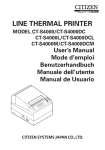
After unpacking the unit, check that all the necessary accessories are included in the package.
Ferrite core
(for dual interface model)
Ferrite core
(for parallel interface model)
Fastener
(for parallel interface model)
Springs
AC Adapter
Tension shaft holders
Power cable
Tension shaft
Setup sheets
Printer
CD-ROM
Thermal label roll paper
Note: When using a thermal label roll paper, do not install the tension bar,
two tension folders, and two springs;
otherwise, a paper jam could result.
Fig. 1-1 Unpacking
If anything is missing, contact the dealer where you bought the printer and ask them to supply
the missing part. Note that it is a good idea to keep the original box and all the packing materials
just in case you need to pack the printer up again and send it somewhere at a later date.
–1–
2. Parts Identification and Nomenclature
Printer cover
Front cover
Open this cover to
load or replace paper.
Do not open the cover
while printing.
Push the center of the front cover
to open the printer cover.
Control panel
Power switch
Features LED indicators to indicate
printer status and switches to
operate the printer.
Used to turn on/off
power to the printer.
Dual Interface Model
USB interface
RS-232 interface
Power connector
For connection to a host
computer.
However, it cannot be
connected concurrently
with RS-232.
For connection to a host
computer.
However, it cannot be
connected concurrently
with USB.
For connection of the
AC adapter.
Never unplug the AC
adapter while the
printer is on.
Parallel Interface Model
Parallel interface
Power connector
For connection to a host
computer.
For connection of the
AC adapter.
Never unplug the AC
adapter while the
printer is on.
–2–
Choosing a place for the printer
Before actually unpacking the printer, you should take a few minutes to think about where
you plan to use it. Remember the following points when doing this.
✓ Choose a firm, level surface where the printer will not be exposed to vibration.
✓ The power outlet you plan to connect to for power should be nearby and unobstructed.
✓ Make sure that the printer is close enough to your host computer for you to connect the
two.
✓ Make sure that the printer is not exposed to direct sunlight.
✓ Make sure that the printer is well away from heaters and other sources of extreme heat.
✓ Make sure that the surrounding area is clean, dry, and free of dust.
✓ Make sure that the printer is connected to a reliable power outlet. It should not be on the
same electric circuit as copiers, refrigerators, or other appliances that cause power
spikes.
✓ Make sure that the room where you are using the printer is not too humid.
WARNING
✓ Shut down your equipment immediately if it produces smoke, a strange odor, or unusual
noise. Immediately unplug the equipment and contact your dealer for advice.
✓ Never attempt to repair this product yourself. Improper repair work can be dangerous.
✓ Never disassemble or modify this product. Tampering with this product may result in
injury, fire, or electric shock.
CAUTION
✓ When using a thermal label roll paper, do not install the tension bar, two tension folders,
and two springs; otherwise, a paper jam could result.
–3–
3. Setup
3-1. Connecting the Cable to the PC
3-1-1. USB Interface cable
Connect the USB interface cable to a USB port of your PC.
Note:The dialog shown below may appear on your PC screen if your PC is running Windows
98 or Me, and if you turn ON the power of the printer for the first time while the PC
and the printer are connected with the USB cable. In this case, refer to the software
manual on the CD-ROM, in the following directory: Documents folder.
3-1-2. RC-232 Interface Cable
Connect the RC-232 interface cable to a RS-232 port of your
PC.
3-1-3. Parallel Interface Cable
Connect the parallel interface cable to a parallel port of your
PC.
–4–
3-2. Connecting the Cable to the Printer
Note that the interface cable is not provided. Please use a cable that meets specifications.
3-2-1. USB Interface Cable
Affix the ferrite core onto the USB cable as shown in the illustration below and make sure to pass
the cable through the cable support as shown in the illustration.
Note:The dialog shown below may appear on your PC screen if your PC is running
Windows 98 or Me, and if you turn ON the power of the printer for the first time
while the PC and the printer are connected with the USB cable. In this case, refer
to the software manual on the CD-ROM, in the following directory: Documents
folder.
–5–
3-2-2. RS-232 Interface Cable
(1) Make sure the printer is turn off.
CAUTION
Before connecting/disconnecting the interface cable, make sure that power to the printer and all
the devices connected to the printer is turned off. Also make sure the power cable plug is
disconnected from the AC outlet.
(2) Connect the interface cable to the connector on the rear panel of the printer.
(3) Tighten the connector screws.
3-2-3. Parallel Interface Cable
Ferrite core
(1) Make sure the printer is turn off.
(2) For only the parallel interface model, affix
the ferrite core onto the cable as shown in
the illustration below.
Interface cable
5 cm
maximum
(3) Pass the fastener through the ferrite core.
Fastener
Pull and cut
(4) Loop the fastener around the cable and
lock it. Use scissors to cut off any excess.
–6–
Parallel interface
cable
(5) Connect the interface cable to the connector on the rear panel of the printer.
(6) Fasten the connector clasps.
3-3. Installing the Printer Software
Here is the procedure for installing the printer driver and utility software, which are stored on the
supplied CD-ROM.
The procedure applies to the Windows operating systems shown below.
3-3-1. Windows 2000/XP
(1)
(2)
(3)
(4)
Turn ON the power to your PC to start Windows.
Insert the supplied CD-ROM (Drivers and Utilities) into the CD-ROM drive.
Follow the instructions that appear on the screen.
The dialog shown in the illustration indicates that the procedure has been completed.
Click “OK”.
The dialog that appears on the screen varies with your system. This completes the installation of
the printer software. A message will appear, prompting you to restart. Restart Windows.
3-3-2. Windows 98/ME
No setup program is provided.
For the installation procedure, please read the PrinterDriverManual_En.pdf file in the Documents/SoftwareManualForWindows/English folder on the CD-ROM.
–7–
3-4. Connecting the AC Adapter
Note:Before connecting/disconnecting the AC adapter, make sure that power to the printer
and all the devices connected to the printer are turned off. Also make sure the power
cable plug is disconnected from the AC outlet.
(1) Connect the AC adapter to the power cable.
Note:Use only the standard AC adapter and power cable.
(2) Connect AC adapter to the connector on the printer.
s
(3) Insert the power cable plug into an AC outlet.
CAUTION
When disconnecting the cable, take hold of the cable connector to pull it out.
Releasing the lock makes it easy to disconnect the connector.
Pulling the cable excessively could cause damage to the connector.
–8–
3-5. Turning Power On
Make sure that the Power cord has been connected as described in 3-4.
Turn ON the power switch located on the front of the printer.
The POWER lamp on the control panel will light up.
Power switch
CAUTION
We recommend that you unplug the printer from the power outlet whenever you do not plan to use
it for long periods. Because of this, you should locate the printer so that the power outlet it is
plugged into is nearby and easy to access.
When an Switch blind is affixed to the printer above the power switch, the ON/OFF marks of the
power switch may be hidden. If this occurs, remove the power cord from the outlet to turn the
printer OFF.
Note: The dialog shown below may appear on your PC screen if your PC is running Windows
98 or Me, and if you turn ON the power of the printer for the first time while the PC
and the printer are connected with the USB cable. In this case, refer to the software
manual on the CD-ROM, in the following directory: Documents folder.
–9–
3-6. Loading the Roll Paper
3-6-1. Thermal Label Roll Paper (Peel Mode)
CAUTION
When using a thermal label roll paper, do not install the tension bar, two tension folders, and two
springs; otherwise, a paper jam could result.
(1) Check that dip switch 1-8 is ON (default:
thermal label roll paper). See Chapter 9 for
instructions on how to set the dip switches.
(2) Turn ON the power switch of the printer.
(3) Push the front cover downward.
(4) Open both the outer and inner printer covers.
(5) Adjust the roll paper guide to the width of
the roll paper.
– 10 –
(6) Peel off a label that is within 150 mm from
the end of the roll paper, and place the roll
paper in the direction shown.
(7) Pull out the end of the backing paper towards you.
(8) Close the inner cover, and firmly press
both its ends.
– 11 –
(9) Turn the end of the backing paper backward.
(10) Push both sides of the printer cover with
your hands as shown, until the printer
cover is securely closed.
(11) Gently pull the end of the backing paper to
take up the slack in the roll paper.
(12) Press the FEED button to bring up the
leading edge of the roll paper.
Note: If the leading edge of a label is not
detected after 300 mm or more of the
roll is fed, the printer will determine
that it is out of paper, and will stop.
Redo the loading of the roll paper
from the beginning.
(13) After printing, the printer will eject a label
as shown, and flash the (red) ERROR
lamp.
(14) Remove the label. The ERROR lamp will
go out when the label is removed.
– 12 –
3-6-2. Thermal Label Roll Paper (Tear Bar Mode)
CAUTION
When using a thermal label roll paper, do not install the tension bar, two tension folders, and two
springs; otherwise, a paper jam could result.
(1) Check that dip switch 1-8 is ON (default:
thermal label roll paper). See Chapter 9 for
instructions on how to set the dip switches.
(2) Turn ON the power switch of the printer.
(3) Push the front cover downward.
(4) Open both the outer and inner printer covers.
(5) Adjust the roll paper guide to the width of
the roll paper.
– 13 –
(6) Peel off a label that is within 100 mm from
the end of the roll paper, and place the roll
paper in the direction shown.
(7) Pull out the end of the backing paper towards you.
(8) Check that the power switch is ON.
(9) Leaving the backing paper as is, close both
the outer and inner covers. Push both sides
of the printer cover with your hands as
shown, until the printer cover is securely
closed.
(10) Cut the portion of the backing paper, which
extends from the front cover, along the tear
bar.
– 14 –
(11) Press the FEED button to bring up the
leading edge of the roll paper.
Note: If the leading edge of a label is not
detected after 300 mm or more of the
roll is fed, the printer will determine
that it is out of paper, and will stop.
Redo the loading of the roll paper
from the beginning.
(12) The printer will eject a label as shown.
3-6-3. Thermal Roll Paper
(1) Check that dip switch 1-8 is OFF (thermal
roll paper).
(2) Turn ON the power switch of the printer.
(3) Push the front cover downward.
(4) Open both the outer and inner printer covers.
(5) Adjust the roll paper guide to the width of
the roll paper.
– 15 –
(6) If the thickness of the paper is 65 to 99 µm, install the tension bar on the printer as shown.
If the thickness of the paper is 100 to 150 µm, it is not necessary to install the tension bar.
Note: Firmly press the tension bar until it clicks into place.
Click
Note: To remove the tension bar, use a slot
screwdriver to undo the clips at each
end of the tension bar, as shown.
Then, remove the tension bar.
(7) Place the roll paper in the direction shown.
– 16 –
(8) Pull out the end of the roll paper towards
you.
(9) Leaving the paper as is, close both the
outer and inner covers. Push both sides of
the printer cover with your hands as shown,
until the printer cover is securely closed.
(10) Cut the portion of the paper that extends
from the front cover.
(11) Press the FEED button to bring up the
leading edge of the roll paper.
Note: If the leading edge of a label is not
detected after 300 mm or more of the
roll is fed, the printer will determine
that it is out of paper, and will stop.
Redo the loading of the roll paper
from the beginning.
(12) The printer will eject a label as shown.
Caution Symbol
This symbol is placed near the thermal print head to indicate that it may be hot. Never
touch the thermal print head immediately after the printer has been used. Let the
thermal print head cool for a few minutes before touching it.
This symbol is placed near the thermal print head to indicate that it is easily damaged.
Observe the precautions for handling electrostatic sensitive devices.
– 17 –
WARNING
• Do not touch the tear bar blade.
- There is a tear bar blade inside the paper outlet slot. Not only should you not put your hand
in the paper outlet slot while printing is in progress, never put your hand into the outlet even
when printing is not in progress.
Tear bar
Tear bar
• During and immediately after printing, the area around the thermal head is very hot. Do not
touch it, as you could be burned.
CAUTION
•
•
•
•
•
•
•
•
•
•
•
Do not push the front cover and open the printer cover when printing is in progress.
Do not push the front cover while pressing on the printer cover with your hand.
Do not pull out paper while the printer cover is closed.
The heating element and the driver IC of the thermal head are easily damaged. Do not touch
them with metal objects, sandpaper, etc.
Printing quality may suffer if the thermal head heating element becomes soiled by being
touched with your hands. Do not touch the thermal head heating element.
There is a risk of damage to the driver IC of the thermal head from static electricity. Never
directly touch the IC.
The printing quality and working life of the thermal head cannot be guaranteed if any paper
other than that recommended is used. In particular, paper containing Sodium, Potassium,
Chlorine may drastically reduce the working life of the thermal head. Please exercise caution.
Do not operate the printer if there is moisture on the front surface of the head from
condensation, etc.
Do not change the width of the roll paper, as this will substantially reduce the use life of the
thermal head and printing quality.
Do not switch to thermal roll paper after using thermal label roll paper because the
deterioration of the thermal head and the accumulation of adhesive residue may negatively
affect print quality.
Because short labels peel easily, the detached labels could stray away from the outlet slot. To
prevent this from occurring, use the command, memory switch, or printer driver to reduce the
printing speed. For instructions on the command and the memory switch, see the separate
Specification Manual. For instructions on the printer driver, see the software manual on the
CD-ROM.
– 18 –
4. Thermal Roll Paper Specification
When consumable parts have run out, use those specified below.
Note:
Access the following URL for the information of the recommended paper.
http://www.star-m.jp/eng/dl/dl02.htm
4-1. Thermal Label Roll Paper
• Backing paper width:
45 ± 0.5 mm to 112 ± 0.5 mm
• Paper thickness:
190 µm maximum
• Roll paper outer dimensions
Roll diameter:
ø110 mm maximum roll diameter
Overall width:
45 ± 0.5 mm to 112 ± 0.5 mm
• Core inner/outer diameters: core inner diameter ø25.4 ± 1 mm/core outer diameter ø32 ± 1 mm
• Finished state of label roll paper:
Make sure the finished state of the label roll paper meets the following conditions:
1) Face the label surface of the (thermal) label paper outward of the roll.
2) Do not allow the core to protrude from the ends of the label roll paper.
3) Do not secure the tail end of the label roll paper with glue or tape. Do not fold the tail end
of the paper.
4) Do not allow the label roll paper to unravel.
5) Do not allow the label roll paper to become deformed at its outer diameter or core.
– 19 –
• Recommended label paper:
Thickness (µ m)
Manufacturer
Product name
Lintec
LD2114
Lintec
Quality features/applications
Base
material
Separator
Total
thickness
Adhesion type
High sensitivity, for handheld
65
50
115
High adhesion
LD3330
High sensitivity, for distribution
87
65
152
High adhesion
Lintec
LD3180
High sensitivity, for distribution
82
65
147
Low adhesion
Lintec
LD9102
Virtual adhesive thermal
117
65
182
High adhesion
Lintec
LD5530
High sensitivity, for measurement
85
65
150
High adhesion
Ojitac
GS75/P22/G6W
High sensitivity
80
60
140
High adhesion
Ricoh
150LA-1
High sensitivity, for foods
—
—
—
High adhesion
Manufacturer
Product name
Lintec
Print density setting
Print speed setting
n
n
LD2114
3 (default)
2
Lintec
LD3330
2
0 (default)
Lintec
LD3180
1
0 (default)
Lintec
LD9102
0
0 (default)
Lintec
LD5530
0
2
Ojitac
GS75/P22/G6W
2
0 (default)
Ricoh
150LA-1
3 (default)
0 (default)
Print Density and Speed Settings
Depending on the type and thickness of the paper, it may be necessary to change
the settings for print density / speed. To change the settings, use the print density setting command
<ESC><RS> ‘d’ n and print speed setting command <ESC><RS> ‘r’ n. Refer to the separate
Specification Manual for details.
– 20 –
• Recommended label paper specifications:
Use roll paper that meets the conditions below.
Printing direction
Base material
(label paper)
4±1
A=36 to 304 (label pitch)
32 to 300 (label length)
Peel paper (backing paper)
2 ± 0.5
41 to 108 ± 0.5 (label width)
45 to 112 ± 0.5 (backing paper width)
(2)
Unit: mm
• Effective printing range:
The printable range of label paper is shown below.
2.5 minimum (left margin)
103 (effective print width: 68 characters, using font A)
{2.5 minimum (right margin)}
2 ± 0.5
41 to 108 ± 0.5 (label width)
45 to 112 ± 0.5 (backing paper width)
– 21 –
A=36 to 304 (label pitch)
32 to 300 (label length)
B=3+A×0.03
(bottom margin)
26 to 294 (effective print length)
3 minimum
(top margin)
Effective print width
(2)
Unit: mm
• Black Mark Specifications
(1) Black mark pitch
Set the black mark pitch A to be within a range of 36 to 304 mm.
(2) Black mark dimensions
Set the black mark dimensions to be printed in accordance with the recommended black
mark label paper specifications below.
(3) PCS value
Set the PCS value for the black mark to be printed to a minimum of 0.90.
Note: If the PCS value for the black mark does not meet the specification above, the printer
could malfunction, such as skipping pages or detecting page lengths improperly.
(4) Bottom margin
Make sure to provide an ample bottom margin, extending from the back end of the printing
range to next printed black mark. Without providing an ample bottom margin, the printer
could malfunction, such as skipping pages. Make sure the printing range setting does not
exceed the black mark pitch.
The bottom margin must be set by considering the following: the printing accuracy of the
black mark pitch, print leading accuracy (standard printing position ± 2 mm), printer
installed ambient temperature, and extent of part wear. We recommend that you set the
printing range by securing the bottom margin as indicated below.
Bottom margin (dimension B) 3 mm + (dimension A × 3%)
(5) Recommended black mark label paper specifications.
Black mark
(back of diagram)
Printing direction
Base material
(label paper)
13
A=36 to 304 (label pitch)
14
4±1
32 to 300 (label length)
Peel paper (backing paper)
2 ± 0.5
41 to 108 ± 0.5 (label width)
45 to 112 ± 0.5 (backing paper width)
– 22 –
(2)
Unit: mm
(6) Effective printing range when using label paper with black mark specifications.
2.5 minimum (left margin) 103 (effective print width: 68 characters, using font A)
{2.5 minimum (right margin)}
A=36 to 304 (label pitch)
32 to 300 (label length)
B=3+A×0.03
(bottom margin)
26 to 294 (effective printing length)
3 minimum
(top margin)
Effective print width
Unit: mm
2 ± 0.5
41 to 108 ± 0.5 (label width)
45 to 112 ± 0.5 (backing paper width)
– 23 –
(2)
4-2. Thermal Roll Paper
• Paper width: 45 ± 0.5 mm to 112 ± 0.5 mm
• Paper thickness: 65 µm to 150 µm
• Roll paper outer dimensions
Roll diameter: ø110 mm maximum roll diameter
Overall width: 45 ± 0.5 mm to 112 ± 0.5 mm
• Core inner/outer diameters:
(1) When 65 µm paper thickness 75 µm
core inner diameter ø12 ± 1/core outer diameter ø18 ± 1
or core inner diameter ø25.4 ± 1 mm/core outer diameter ø32 ± 1 mm
(2) When 76 µm paper thickness 150 µm
core inner diameter ø25.4 ± 1 mm/core outer diameter ø32 ± 1 mm
• Finished state of roll paper:
Make sure the finished state of the roll paper meets the following conditions:
1) Face the coloring surface of the thermal roll paper outward of the roll.
2) Do not allow the core to protrude from the ends of the thermal roll paper.
3) Do not secure the tail end of the thermal roll paper with glue or tape. Do not fold the tail end
of the paper.
4) Do not allow the thermal roll paper to unravel.
5) Do not allow the thermal roll paper to become deformed at its outer diameter or core.
• Recommended thermal paper:
Manufacturer
Mitsubishi Paper
Mills Limited
Thickness
(µ m)
Print density setting
n
Print speed setting
n
Normal type
65
3 (default)
0 (default)
2-color type red-black/blue-black
87
3 (default)
0 (default)
Product name
Quality features/applications
P220AG
PB670/PB770
Print Density and Speed Settings
Depending on the type and thickness of the paper, it may be necessary to change
the settings for print density / speed. To change the settings, use the print density setting command
<ESC><RS> ‘d’ n and print speed setting command <ESC><RS> ‘r’ n. Refer to the separate
Specification Manual for details.
– 24 –
5. Control Panel and Other Functions
5-1. Control Panel
3 FEED button
2 ERROR lamp (Red LED)
1 POWER lamp (Green LED)
1 POWER lamp (Green LED)
Lights when the power is ON.
2 ERROR lamp (Red LED)
Indicates various errors in combination
with POWER lamp.
3 FEED button
Press the FEED button to feed roll paper.
5-2. Errors
1) Automatically recoverable errors
Error Description
Head high temperature
detection
Cover open error
POWER Lamp
Flashes at 0.5-second
intervals
On
Label/black mark detec- On
tion error or paper out
error
Label page error
On
Peeler sensor error
On
ERROR Lamp
Off
Recovery Conditions
Automatically recovered after the
print head has cooled.
On
Close the printer cover. Then, press
the FEED button.
Flashes at 0.5-second Replace the label roll paper or the
intervals
black mark roll paper. Then, press
the FEED button.
Flashes at 1-second Replace the label roll paper or change
intervals
the transmission data.
Flashes at 0.125-sec- Discard the peeled label.
ond intervals
– 25 –
2) Non-recoverable errors
Error Description
Head thermistor error
POWER Lamp
Off
Power voltage error
Off
EEPROM error
Off
Flash access error
Off
SRAM error
Off
ERROR Lamp
Flashes at 1.5-second intervals
Flashes at 2-second intervals
Recovery Conditions
This is not a recoverable error.
This is not a recoverable error.
Flashes at 0.75-second in- This is not a recovertervals
able error.
Flashes at 0.5-second inter- This is not a recovervals
able error.
Flashes at 1-second intervals This is not a recoverable error.
Note:
1) If a non-recoverable error occurs, turn the power OFF immediately.
2) If a non-recoverable error occurs, please consult the dealer for repairs.
5-3. Self-Printing
5-3-1. Test Printing
Place the thermal label roll paper or thermal roll paper on the
printer.
Turn the power ON while holding the FEED button depressed. The printer will run a test print according to the Ver.
No., DIP switch settings, and memory switch settings.
5-3-2. Hexadecimal Dump Mode
Place the thermal roll paper on the printer.
Open the printer cover, then turn the power on while holding
the FEED button.
When the cover is closed, “*** HEX DUMP PRINTING
***” is printed, and the printer enters the Hexadecimal
Dump Mode.
Each of the signals sent from the computer to the printer will
be printed out in hexadecimal code.
This function allows you to check if a control code sent to the
printer by the program being used is correct or not. The final
line is not printed if its data is less than one full line.
However, if the FEED button is pushed, the final line is
printed. To turn off the mode, it is necessary to turn off the
printer completely.
– 26 –
5-4. Adjusting the Sensors
This printer is equipped with three types of paper sensors.
C
B
A
Light Emitter
A
Light Receiver
A. Label roll paper transmission type sensor
This sensor detects the presence of the
backing paper for the label roll paper.
Because this sensor is affected by the thickness and the color of the backing paper of
the label roll paper, the sensor might require an adjustment, depending on the
label roll paper that is used.
B. Label paper reflection type sensor
This sensor detects the presence of the
label roll paper and the black mark.
C. Label roll paper peeler sensor
This sensor detects the presence of the
label roll paper that has been peeled.
5-4-1. Adjusting the label roll paper transmission type sensor
DIP Switch 1
1
2
3
4
5
6
DIP Switch 2
OFF
ON
VR3
(1) Set the backing paper of the label roll paper
against the label roll paper transmission
type sensor. Then, close the printer cover.
It is the backing paper, not the label portion, which must be set against the label
roll paper transmission type sensor.
(2) Turn OFF the power to the printer. (For
safety, unplug the power cable from the
outlet.)
(3) Undo the screw and remove the dip switch
cover from the bottom of the printer.
(4) To activate the sensor adjustment mode,
use a pointed object to set the dip switches
as follows:
DSW 1-4 = OFF, DSW 1-5 = ON,
DSW 1-6 = ON, DSW 1-7 = ON
(5) Turn ON the power switch of the printer.
The two lamps will flash on the control
panel to indicate that the sensor adjustment mode has been activated.
– 27 –
7
8
1
2
3
4
(6) If the two lamps remain ON after flashing, it means that the sensor is adjusted properly and
does not require further adjustment.
(7) If both the ERROR and POWER lamps are OFF, use a plastic slot screwdriver to turn and
adjust the VR3 knob to a position in which both the ERROR and POWER lamps are ON.
If the adjustment has been successful, proceed to (10).
(8) If the adjustment has not been successful, press the FEED button. The two lamps on the
control panel will flash to indicate that the light emitting level of the sensor has been changed
by one step. Then, as in (7), turn and adjust the VR3 knob to a position in which both the
ERROR and POWER lamps are ON. If the adjustment has been successful, proceed to (10).
(9) If the adjustment has not been successful, press the FEED button again. The two lamps on the
control panel will flash to indicate that the light emitting level of the sensor has been changed
by one step. Then, as in (7), turn and adjust the VR3 knob to a position in which both the
ERROR and POWER lamps are ON. If the adjustment has been successful, proceed to (10).
If the adjustment has not been successful, have the printer repaired.
(10) Turn OFF the power switch.
(11) Set the dip switch SW1-4 to ON.
(12) Return the dip switches SW1-5, SW1-6, and SW1-7 to their original settings.
The light emitting level of the sensor changes one step at a time, as shown below.
Level 1
1 step
Level 2
(Default)
Level 3
1 step
1 step
5-4-2. Adjusting the reflection type sensor
DIP Switch 1
1
2
3
4
5
6
DIP Switch 2
OFF
ON
VR2
(1) Set the roll paper against the reflection
type sensor. Then, close the printer cover.
Either thermal label roll paper or thermal
roll paper is acceptable. However, if it has
black marks, set the roll paper in such a
way that a black mark is not placed against
the sensor.
(2) Turn OFF the power to the printer. (For
safety, unplug the power cable from the
outlet.)
(3) Undo the screw and remove the dip switch
cover from the bottom of the printer.
(4) To activate the sensor adjustment mode,
use a pointed object to set the dip switches
as follows:
DSW 1-4 = OFF, DSW 1-5 = ON,
DSW 1-6 = ON, DSW 1-7 = ON
– 28 –
7
8
1
2
3
4
(5) Press and hold the FEED button, and turn
ON the power switch of the printer. The
two lamps will flash on the control panel to
indicate that the sensor adjustment mode
has been activated. After the lamps flash,
release your finger from the button.
(6) If the two lamps remain ON after flashing, it means that the sensor is adjusted properly and
does not require further adjustment. Proceed to (8).
(7) If both the ERROR and POWER lamps are OFF, turn and adjust the VR2 knob to a position
in which both lamps are ON. If the adjustment has not been successful, have the printer
repaired.
(8) Turn OFF the power switch and set the dip switch SW1-4 to ON.
(9) Return the dip switches SW1-5, SW1-6, and SW1-7 to their original settings.
5-4-3. Adjusting the label roll paper peeler sensor
1
2
OFF
ON
VR1
(1) Remove the roll paper from the printer.
Verify that there is no paper in the vicinity
of the peeler sensor, and close the printer
cover.
(2) Turn OFF the power to the printer. (For
safety, unplug the power cable from the
outlet.)
(3) Undo the screw and remove the dip switch
cover from the bottom of the printer.
(4) To activate the sensor adjustment mode,
use a pointed object to set the dip switches
as follows:
DSW 1-4 = OFF, DSW 1-5 = OFF,
DSW 1-6 = ON, DSW 1-7 = ON
(5) Turn ON the power switch of the printer.
The two lamps will flash on the control
panel to indicate that the sensor adjustment mode has been activated.
– 29 –
3
4
5
6
7
8
1
2
3
4
(6) After the lamps have flashed, turn the VR1 knob fully counterclockwise. The adjustment has
been completed if the POWER lamp is ON. Proceed to (8). The ERROR lamp may be ON
or OFF.
(7) If the POWER lamp is not ON, turn and adjust the VR1 knob to a position in which both the
ERROR and POWER lamps are ON. If the adjustment has been successful, proceed to (8).
If the adjustment has not been successful, have the printer repaired.
(8) Turn OFF the power switch and set the dip switch SW1-4 to ON.
(9) Return the dip switches SW1-5, SW1-6, and SW1-7 to their original settings.
– 30 –
6. Preventing and Clearing Paper Jams
6-1. Preventing Paper Jams
The paper should not be touched during ejection and printing.
Pressing or pulling the paper during ejection may cause a paper jam or line feed failure.
6-2. Removing Paper Jam
If a paper jam occurs, clear it as described below.
(1) Set the power switch to off to turn off power to the printer.
(2) Push the front cover and open the printer cover.
(3) Remove the jammed paper.
CAUTION
Take care not to damage the printer when removing the jammed paper.
Since it is easy to damage the thermal head in particular, take care not to touch it.
(4) Position the roll paper straight and close the printer cover gently.
Note 1: Make sure that the paper is positioned straight. If the printer cover is closed with
the paper skewed, a paper jam may result.
Note 2: Lock the printer cover by pressing down on the sides. Do not try to close it by
pressing down on the center. The cover may not lock properly.
(5) Set the power switch to on to turn on power to the printer. Make sure that the ERROR LED
is not lit.
Note: While the ERROR LED is lit, the printer will not accept any commands such as the
print command, so make sure that the printer cover is locked properly.
– 31 –
7. Periodic Cleaning
At times, the printer might leave some characters partially unprinted due to paper particles or
debris from the adhesive used on label paper. As a preventive measure, clean the printer regularly
every month or after printing 200,000 lines.
7-1. Cleaning the Thermal Head and Ground Hardware
Use the optional head cleaner as shown to remove the grime from the thermal head. A cotton swab
or soft cloth dipped in an alcohol solution (such as ethanol, methanol, or isopropyl alcohol) may
be used instead of the head cleaner. Follow the cleaning instructions below.
Ground hardware
Thermal head
Optional head cleaner
(1) Cut off the power to the printer by turning
OFF the power switch.
(2) Push the front cover to open the printer
cover.
(3) Using the head cleaner, wipe off the black
paper particles that have accumulated on
the thermal head surface.
(4) Likewise, use the head cleaner to wipe off the
paper particles that have accumulated on the
ground hardware above the thermal head.
Notes
1: Do not clean the thermal head immediately after printing, because the thermal head is hot.
2: While cleaning the thermal head, be careful not to create static electricity, which poses
the risk of problems such as damage to the head.
3: Turn the power ON only after the alcohol solution has completely dried.
7-2. Cleaning the Printer Cover, Paper Guide, and Peeler Sensor
Using a cotton swab or soft cloth dipped in an alcohol solution (such as ethanol, methanol, or
isopropyl alcohol), remove paper particles or glue debris from the areas shown below.
Ribs of peeling line holder
Above ribs
Ribs of paper guide
– 32 –
8. Specifications
8-1. General Specifications
(1)
(2)
(3)
(4)
(5)
Printing method
Print speed
Dot density
Printing width
Roll paper
(6) Overall dimension
(7) Weight
(8) Noise Approx.
Direct line thermal printing
Max. 150 mm/sec.
203 dpi: 8 dots/mm (0.125 mm/dot)
Max. 104 mm
Refer to chapter 4 for details on the recommended roll paper.
Paper width:44.5 ± 0.5 mm to 111.5 ± 0.5 mm (thermal roll paper)
43 ± 0.5 to 110 ± 0.5 mm (thermal label roll paper)
Roll diameter: ø110 mm or less
180 (W) × 213 (D) × 157 (H) mm
Approx. 2 kg (Not including the I/F board, paper roll or accessories)
Approx. 57 dB (operating)
– 33 –
8-2. Interface
• Bidirectional parallel interface: IEEE 1284 compatibility and nibble modes
• Dual interface: RS-232 D-Sub 9 pin
USB
USB type-B connector
8-3. Electrical Characteristics
(1) Input:
100 to 240V AC, 50/60 Hz
(2) Output:
DC 24V ± 5%
(3) Current Consumption Operating: Approx. 2.0 A (at ASCII printing)
Approx. 10 A (at print duty 100%, for 10 seconds or less)
Peak:
Stand-by: Approx. 0.1 A
(4) Power Connector
Pin No.
1
2
3
Shell
Function
Drive power (24V)
Signal GND
N.C.
Frame ground
1
3
2
<Viewed from Connector Surface>
Notes:
• When using a printer power supply other than the optional AC adaptor (PS60A-24A), be
sure that the following cautions are observed.
• Use a power supply of DC 24 V ± 5% and more than 2.0 A (5.0 A Load 10 sec. Min.) with
SELV output and LPS or Class 2 output approved by IEC60950.
• Be careful about installing the printer in an area where there is noise. Take the appropriate
measures to protect against electrostatic AC line noise, etc.
– 34 –
8-4. Environmental Requirements
(1) Operating
Temperature
Humidity
5°C to 45°C
10% to 90% RH (without condensation)
(%RH)
34°C 90% RH
90
Relative humidity
80
40°C 65% RH
60
45°C 50% RH
40
Operating environment
range
20
10
0
10
20
30
40
50
Temperature (°C)
Operating temperature and humidity range
(2) Transport/storage (except for paper)
Temperature
-20°C to 60°C
Humidity
10% to 90% RH (without condensation)
8-5. Reliability
1) Life
Mechanical:
Head:
15 million lines
100 million pulses, 100 km (±15% max. average head resistance
fluctuation)
<Conditions>
Average printing ratio:
12.5%
Standard printing density setting (monochrome printing mode)
2) MCBF: 37 million lines
The Mean Cycle Between Failure (MCBF) is defined to be the overall failure cycle, which
includes random or wear failures that occur until the printer reaches its mechanical life of
15 million lines.
* As the mechanical remains at 15 million lines, the MCBF of 37 million lines does not
indicate its useful life.
* All the reliability values indicated above are based on the use of the recommended thermal
paper. No reliability can be guaranteed for the use of non-recommended thermal paper.
– 35 –
9. Dip Switch Setting
Two DIP switches are provided at the bottom of the printer, and can be set as given in the table
below. Be sure to set the power switch to off before changing the settings. It is recommended to
use a pointed item like a pen or flat-blade driver screw to change the settings. The settings will
become effective when the power switch is set to on again.
The following is the procedure for changing the settings on DIP switches.
1.
Make sure the printer is turned off.
2.
Remove the screw from the DIP switch cover. Then take off the DIP switch cover, as shown
in the illustration below.
DSW 1
1
2
3
4
5
DSW 2
6
7
8
1
2
3
4
OFF
ON
3.
Set the switches using a pointed tool, such as a pen or flat-blade screwdriver.
4.
Replace the DIP switch cover. Then secure it with the screw.
The new settings take effect when you turn on the printer.
– 36 –
9-1. Parallel Interface Type
ON
ON
OFF
OFF
No. 1 2 3 4 5 6 7 8
No. 1 2 3 4
DIP-SW2
DIP-SW1
DIP-SW 1
Switch
1-1
1-2
1-3
1-4
1-5
1-6
1-7
1-8
Function
ON
OFF
Command emulation
See table below
Should not be changed (Should be set to on)
Sensor adjustment
Pin #31 (INIT) reset signal
Handshaking conditions
(conditions for BUSY)
Selection of detector for thermal
label paper (*1)
Selection of roll paper (*2)
Valid
Valid
Offline or receive
buffer full
Transmission type
detector
Thermal label roll paper
Invalid
Invalid
Receive buffer full
Reflection type detector
Thermal roll paper
The factory settings of DIP switch are all on.
Emulation
Switch 1-1
ON
OFF
ON
OFF
Switch 1-2
ON
ON
OFF
ON
Emulation
STAR Line Mode
STAR Page Mode
(reserved)
(reserved)
Notes:
*1) Only a reflection type detector may be used on thermal roll paper.
*2) Two modes are available for the thermal label roll paper: a peeler mode and a tear bar
mode (without using peeler). These modes are recognized automatically.
DIP-SW 2
Switch
2-1
2-2
2-3
2-4
Function
ON
Always ON
OFF
Should be set to on
The factory settings of DIP switch are all on.
– 37 –
9-2. Dual Interface Type
<Switching the Dual Interface Modes>
The dual interface enables the connection of an RS-232 interface and a USB interface, although
they cannot be connected concurrently.
The printer starts with the RS-232 interface at the time its power is turned ON.
Afterwards, it will switch automatically to the USB interface if a USB cable that is connected to
a computer is connected to the dual interface.
However, if a USB cable is connected to the printer while the power to the computer is OFF, the
printer will not switch automatically to the USB interface connection.
Once the printer has recognized a USB connection, it will continue to assume this connection
until its power is turned OFF, even if you disconnect the USB cable.
9-2-1. USB Interface Type
ON
OFF
ON
OFF
No. 1 2 3 4 5 6 7 8
No. 1 2 3 4
DIP-SW2
DIP-SW1
DIP-SW 1
Switch
1-1
1-2
1-3
1-4
1-5
1-6
1-7
1-8
Function
ON
Command emulation
See table below
Should not be changed (Should be set to on)
Sensor adjustment
USB mode
Handshaking conditions
(conditions for BUSY)
Selection of detector for thermal
label paper (*1)
Selection of roll paper (*2)
Valid
Printer Class
Offline or receive
buffer full
Transmission type
detector
Thermal label roll paper
OFF
Invalid
Vendor Class
Receive buffer full
Reflection type detector
Thermal roll paper
The factory settings of DIP switch are all on.
Emulation
Switch 1-1
ON
OFF
ON
OFF
Switch 1-2
ON
ON
OFF
ON
Emulation
STAR Line Mode
STAR Page Mode
(reserved)
(reserved)
Notes:
*1) Only a reflection type detector may be used on thermal roll paper.
*2) Two modes are available for the thermal label roll paper: a peeler mode and a tear bar
mode (without using peeler). These modes are recognized automatically.
– 38 –
DIP-SW 2
Switch
2-1
2-2
2-3
2-4
Function
ON
Always ON
OFF
Should be set to on
The factory settings of DIP switch are all on.
9-2-2. RS-232 Interface Type
ON
OFF
ON
OFF
No. 1 2 3 4 5 6 7 8
No. 1 2 3 4
DIP-SW2
DIP-SW1
DIP-SW 1
Switch
1-1
1-2
1-3
1-4
1-5
1-6
1-7
1-8
Function
ON
Command emulation
OFF
See table below
Should not be changed (Should be set to on)
Sensor adjustment
Should not be changed (Should be set to on)
Handshaking conditions
(conditions for BUSY)
Selection of detector for thermal
label paper (*1)
Selection of roll paper (*2)
Valid
Invalid
Offline or receive
Receive buffer full
buffer full
Transmission type
Reflection type detector
detector
Thermal label roll paper Thermal roll paper
The factory settings of DIP switch are all on.
Emulation
Switch 1-1
ON
OFF
ON
OFF
Switch 1-2
ON
ON
OFF
ON
Emulation
STAR Line Mode
STAR Page Mode
(reserved)
(reserved)
Notes:
*1) Only a reflection type detector may be used on thermal roll paper.
*2) Two modes are available for the thermal label roll paper: a peeler mode and a tear bar
mode (without using peeler). These modes are recognized automatically.
– 39 –
DIP-SW 2
Switch
2-1
2-2
2-3
2-4
Function
ON
Always ON
OFF
Should be set to on
■ DIP Switch 3
The factory settings of DIP switch are all on.
The following is the procedure for changing the settings on DIP switch No. 3.
1. Turn off the printer and all components connected to it.
2. Remove the 2 screws.
3. Remove the dual interface board unit.
4. Change the setting of the DIP switches.
5. Replace the dual interface board unit.
6. Then secure it with the screws.
7. Turn on the printer and all components connected to it.
DIP switch 3
DIP-SW3
The factory settings of DIP switch are all on, except for switches 1, 2, 7 and 8.
– 40 –
DIP-SW 3
Switch
3-1
3-2
3-3
3-4
3-5
3-6
3-7
3-8
Baud Rate
4800BPS
9600BPS
19200BPS
38400BPS
Function
ON
Baud Rate
OFF
See table below
Data Length
Parity Check
Parity
Handshake
8 bits
Disabled
Odd
DTR
7 bits
Enabled
Even
XON/XOFF
Should not be changed (Should be set to off)
—
—
Switch 3-1
OFF
ON
ON
OFF
Switch 3-2
ON
ON
OFF
OFF
– 41 –
10. Parallel Interface
The two-way parallel interface is compatible with the IEEE1284 compatibility mode and nibble
mode. Refer to the separate specification manual for details.
Table of Connection Signals for Each Mode
Pin No.
Direction
Compatibility Mode
Signal Name
Nibble Mode
Signal Name
1
2
3
4
5
6
7
8
9
10
11
12
13
14
15
16
17
18
19-30
31
32
33
34
35
36
In
In/Out
In/Out
In/Out
In/Out
In/Out
In/Out
In/Out
In/Out
Out
Out
Out
Out
nStrobe
Data0
Data1
Data2
Data3
Data4
Data5
Data6
Data7
nAck
Busy
PError
Select
—
—
Signal GND
Frame GND
+5V
Twisted Pair Return
nInit
nFault
External GND
Compulsion
—
nSelectIn
Host Clock
Data0
Data1
Data2
Data3
Data4
Data5
Data6
Data7
PtrClk
PtrBusy/Data3, 7
AckDataReq/Data2, 6
Xflag/Data1, 5
HostBusy
—
Signal GND
Frame GND
+5V
Twisted Pair Return
nInit
nDataAvail/Data0,4
—
—
—
1284Active
Out
In
Out
In
This connector mates with an
Amphenol 57-30360 connector
Parallel interface connector (printer side)
– 42 –
11. Dual Interface
11-1. RS-232 Interface
11-1-1. Interface Specifications
1 Data transmission method:
2 Baud rate:
3 Word length
4 Signal polarity
Asynchronous serial interface
Selectable from 4800, 9600, 19200, 38400 bps
(Refer to “9. DIP Switch Setting”.)
Start bit: 1 bit
Data bit: 7 or 8 bits (selectable. Refer to “9. DIP Switch
Setting”.)
Parity bit: Odd, even or none (selectable. Refer to “9. DIP
Switch Setting”.)
Stop bit: 1 bit length
RS-232
MARK: Logic “1” (–3V to –15V)
SPACE: Logic “0” (+3V to +15V)
MARK “1”
SPACE “0”
A: Start bit
B: Data bit
C: Parity bit
D: Stop bit
– 43 –
11-1-2. Connectors and Signal Names
RS-232
Pin No.
–
1
2
3
4
Signal name
FG
N.C
RXD
TXD
DTR
Direction
—
—
IN
OUT
OUT
5
6
7
8
9
S-GND
DSR
RTS
CTS
N.C
—
IN
OUT
IN
—
Function
Frame ground
Not used
Receiving data
Transmission data
Indicates whether data receive from host is enabled or disabled.
1) DTR Communication Mode
Space when receive is enabled.
2) X-On/X-Off Communication Mode
Always space, except during following conditions:
• Period between reset and communication enabled
• During self printing
Signal ground
Status of this signal is not checked
Always space
Status of this signal is not checked
Not used
D-sub 9 Pin
– 44 –
11-1-3. Cable Connections
The followings are a recommended interface cable connections.
Printer side
(D-sub 9 pin)
NC
1
RXD
2
TXD
Host side
9 pin
25 pin
1
FG
2
3
RXD
3
3
2
TXD
DTR
4
7
4
RTS
SG
5
5
7
SG
DSR
6
8
5
CTS
RTS
7
6
6
DSR
CTS
8
1
8
DCD
NC
9
4
20
DTR
Note: Use shielded wire less than 3 m in length.
11-2. USB Interface
11-2-1. USB Function
1.
2.
3.
4.
General Specification: Conforms to USB 2.0 Specifications
Communication Speed: USB Full Speed Mode (12 Mbps)
Communication Method: USB Bulk Transmission Mode
Power Specifications:
USB Self-power Function
11-2-2. Connector
• USB Up-Stream Port Connector (USB Type-B)
– 45 –
12. Memory Switch Settings
Each memory switch is stored in EEPROM. For details on the functions and settings of memory
switches, see the separate Specification Manual.
The table below shows the factory settings for the memory switches.
Memory Switch
0
1
2
3
4
Hexadecimal Code
0000
0000
0000
0000
0000
Warning!
Changing the memory switch settings can cause the printer to fail to operate correctly.
– 46 –
ELECTRONIC PRODUCTS DIVISION
STAR MICRONICS CO., LTD.
OVERSEAS SUBSIDIARY COMPANIES
STAR MICRONICS AMERICA, INC.
536 Nanatsushinya, Shimizu-ku, Shizuoka,
424-0066 Japan
Tel: 0543-47-0112, Fax: 0543-48-5013
1150 King Georges Post Road, Edison, NJ 08837-3729 U.S.A.
Tel: 732-623-5555, Fax: 732-623-5590
Please access the following URL
http://www.star-m.jp/eng/dl/dl02.htm
for the latest revision of the manual.
STAR MICRONICS U.K. LTD.
Star House, Peregrine Business Park, Gomm Road,
High Wycombe, Bucks, HP13 7DL, U.K.
Tel: 01494-471111, Fax: 01494-473333
2006.01.18
Printed in China, 80870460CD