1
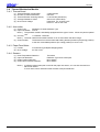
Product Specifications Manual TUP900 Series Rev. 0.01 Star Micronics Co., Ltd. Special Products Operating Division Rev 0.01 --- CONTENTS --1. GENERAL DESCRIPTION ...................................................................................................................1-1 2. PRINTER CONFIGURATION...............................................................................................................2-1 2-1 Basic Configuration...............................................................................................................................2-1 2-1-1 Thermal Mechanism Module ......................................................................................................2-1 2-1-2 Presenter Module .......................................................................................................................2-1 2-1-3 Control Board Module ................................................................................................................2-1 2-1-4 Power Connector Cable Module ................................................................................................2-1 2-1-5 Paper Roll Supply Module..........................................................................................................2-1 2-2 Selectable Options for Each Module ....................................................................................................2-1 3. BASIC SPECIFICATIONS ....................................................................................................................3-1 3-1 Printing Specifications ..........................................................................................................................3-1 3-2 Character Specifications and Bar Code Specifications ........................................................................3-2 3-2-1 STAR Line Mode ........................................................................................................................3-2 3-2-2 STAR Page Mode ......................................................................................................................3-3 3-3 Paper Specifications .............................................................................................................................3-4 3-3-1 Thermal Paper roll......................................................................................................................3-4 3-3-2 Black Mark Specifications ..........................................................................................................3-7 3-4 Thermal Mechanism Module ................................................................................................................3-9 3-4-1 Thermal Head.............................................................................................................................3-9 3-4-2 Auto-cutter..................................................................................................................................3-9 3-4-3 Paper Feed Motor ......................................................................................................................3-9 3-4-4 Sensors ......................................................................................................................................3-9 3-5 Presenter Module ...............................................................................................................................3-10 3-5-1 Feed Rollers .............................................................................................................................3-10 3-5-2 Paper Feed Motor ....................................................................................................................3-10 3-5-3 Sensors ....................................................................................................................................3-10 3-6 Paper Roll Supply Module ..................................................................................................................3-11 3-6-1 Paper Roll Holder .....................................................................................................................3-11 3-6-2 Near-end Sensor ......................................................................................................................3-11 3-7 Reliability Specifications .....................................................................................................................3-12 3-7-1 Thermal Mechanism Module ....................................................................................................3-12 3-7-2 Thermal Head...........................................................................................................................3-12 3-7-3 Auto-cutter................................................................................................................................3-12 3-7-4 Presenter Module .....................................................................................................................3-12 4. EXTERNAL SPECIFICATIONS............................................................................................................4-1 4-1 External Specifications .........................................................................................................................4-1 4-1-1 External Dimensions ..................................................................................................................4-1 4-1-2 External Drawings ......................................................................................................................4-1 4-1-3 Mass...........................................................................................................................................4-1 4-2 Operation Panel Specifications.............................................................................................................4-1 4-2-1 Switches .....................................................................................................................................4-1 4-2-2 LED ............................................................................................................................................4-1 4-3 Interface................................................................................................................................................4-1 4-4 DIP Switches ........................................................................................................................................4-1 5. ENVIRONMENT SPECIFICATIONS ....................................................................................................5-1 5-1 Temperature and Humidity ...................................................................................................................5-1 5-1-1 When Operating .........................................................................................................................5-1 5-1-2 When Stored (Excluding Paper roll) ...........................................................................................5-1 TUP900 Series Specifications Manual i Rev 0.01 5-2 Static Electricity Tolerance (ESD).........................................................................................................5-2 5-3 AC Line Noise Tolerance......................................................................................................................5-2 5-4 Vibrations, Falling Shocks ....................................................................................................................5-2 5-4-1 Vibration Test (When Packaged) ...............................................................................................5-2 5-4-2 Drop Test (When Packaged)......................................................................................................5-2 5-5 Dust ......................................................................................................................................................5-2 6. SAFETY................................................................................................................................................6-1 6-1 Standard ...............................................................................................................................................6-1 7. USAGE EXAMPLE (LAYOUT EXAMPLE) ...........................................................................................7-1 7-1 Control Board Layout............................................................................................................................7-1 7-1-1 Control Board Layout 2 ..............................................................................................................7-1 7-1-2 Control Board Layout 3 ..............................................................................................................7-1 7-2 High Volume Paper Roll Supply (RHU-T900, Optional Part) ................................................................7-1 7-2-1 Horizontal Layout .......................................................................................................................7-1 7-2-2 Vertical Layout............................................................................................................................7-1 8. SETTING UP THE PRINTER UNIT......................................................................................................8-1 8-1 Mounting the Units................................................................................................................................8-1 8-1-1 Mounting the Printer Unit............................................................................................................8-1 8-1-2 Mounting the High Volume Paper Roll Supply (RHU-T900).......................................................8-1 8-1-3 Mounting the Printer Unit and the High Volume Paper Roll Supply (RHU-T900).......................8-1 8-2 Mounting the High Volume Paper Roll Supply (RHU-T900) .................................................................8-1 8-3 Adjusting the Paper roll Holder Unit......................................................................................................8-2 8-3-1 Handling 111.5 mm Paper Width ...............................................................................................8-2 8-3-2 Handling 82 mm Paper Width ....................................................................................................8-2 8-3-3 Handling 79.5 mm Paper Width .................................................................................................8-2 8-4 Mounting the Friction Spring.................................................................................................................8-4 8-4-1 Using the Spring Base................................................................................................................8-4 8-4-2 When Not Using the Spring Base...............................................................................................8-4 8-5 Adjusting the Near End Sensor ............................................................................................................8-8 8-5-1 Adjusting to the Paper roll Width ................................................................................................8-8 8-5-2 Adjusting to the Paper roll Diameter Direction ...........................................................................8-8 9. HANDLING THE PRINTER UNIT.........................................................................................................9-1 9-1 Precautions Regarding Designs ...........................................................................................................9-1 9-2 Precautions for Handling ......................................................................................................................9-1 9-3 Precautions Concerning Safety ............................................................................................................9-2 9-4 How to Set the Paper roll......................................................................................................................9-3 9-5 Performing Maintenance.......................................................................................................................9-7 9-5-1 Cleaning the Thermal Head and Platen .....................................................................................9-7 9-5-2 Handling Recording Paper Jams................................................................................................9-7 9-5-3 How to Release the Cutter Lock.................................................................................................9-7 10. Control board module (TBD900 Series) .......................................................................................... 10—1 11. Power connector cable module (PBD-9) ......................................................................................... 11—2 TUP900 Series Specifications Manual ii Rev 0.01 1. GENERAL DESCRIPTION The TUP900 series is a direct line thermal printer capable of high speed printing that employs a thermal line dot printing system and is composed of a unit comprising thermal paper roll storage. This type is used, embedded in electronic devices such as games, ATM, and information kiosks. Model Name Display Directions TUP9 9 2 – 24 J1 Installed Fonts None: Standard models J1: Japanese Characters Power Specifications 24: 24 VDC Mechanism Type 2: Standard Printer Type 9: Presenter equipped with a recovery function as standard. TUP900 Series Thermal Unit Printer TUP900 Series Specifications Manual 1-1 Rev 0.01 2. PRINTER CONFIGURATION 2-1 Basic Configuration This unit is composed of modules. The configuration is shown below. TUP992-24/TUP992-24J1 (Thermal line unit printers) Thermal mechanism module (TMP900 Series) Presenter module (PR900 Series) Control board module (TBD900 Series) Power connector cable module (PBD-9) Paper roll supply module 2-1-1 Thermal Mechanism Module This is composed of the printer mechanism portion that prints using a thermal head while paper is being fed, and an auto-cutter mechanism that cuts the paper by command. 2-1-2 Presenter Module The presenter module is composed of a mechanism that discharges and that recovers paper (such as receipts) that has been printed and cut by the thermal mechanism module. 2-1-3 Control Board Module This is the control board that controls the thermal mechanism and the presenter. 2-1-4 Power Connector Cable Module This is composed of the connector portion that connects the optional power adapter set to the control board, and the power switch. 2-1-5 Paper Roll Supply Module This supports the thermal paper roll on a shaft and functions to supply paper to the thermal mechanism module. This is also provided a damper roller unit to alleviate the shock caused by the inertia of the paper roll when feeding the thermal paper. 2-2 Selectable Options for Each Module This unit is used by mounting the following selectable options on each module. The following table shows the options for each module. Unit/Module Name TUP992-24 TUP992-24J1 Content of Option Power Adapter TMP900 Series High Volume Paper Roll Supply Near-end Sensor Damper Roller Control Panel Board Unit I/F TBD900 Series Power Connector Cable TUP900 Series Specifications Manual 2-1 Part Number 30781430 30781440 30781450 30781460 30781470 30781480 39590020 Part Name PS60L-24A Adapter Set JP PS60L-24A Adapter Set US PS60L-24A Adapter Set EU PS60L-24A Adapter Set UK PS60L-24A Adapter Set AS PS60L-24A Adapter Set CH RHU-T900 39590030 39591000 39591500 39607400 39607411 39607420 39607430 39607440 39206500 NEU-T900 DRU-T900 OPA-T900 IFBD-HD04 IFBD-HC04 IFBD-HU04 IFBD-HN04 IFBD-HE04 PBD-9 Rev 0.01 3. BASIC SPECIFICATIONS 3-1 Printing Specifications (1) (2) (3) (4) Print Method: Dot Configuration: Dot Density: Printing Region: Direct Thermal Line Printing 832 dots/line 8 dots/mm (203 DPI) Maximum 104 mm (See figure below) 111.5 ±0.5 mm (Maximum paper width) 3.75 mm 104 mm (Maximum print region, 832 dots) 3.75 mm 0.125 mm 0.125 mm Fig. 3.1.4 Print Region Notes 1) The mechanism can handle paper widths of 79.5 ±0.5 to 111.5 ±0.5 mm. However, it is recommended that a print layout is set that allows plenty of print margin on the left and right sides for the paper that is used. Also, the standard position of printing to the paper width is center of the paper width. Left and right margins in the printing region are recommended to be a minimum of 3.75 mm. 2) When using a paper width that is less than the maximum print width of the head (104 mm), consider the recording paper feeding state so that the print region does not leave both edges of the recording paper. (5) (6) (7) (8) (9) (10) (11) (12) (13) (14) Maximum 69 columns (12 × 24 fonts) Maximum 34 columns (24 × 24 Chinese character fonts) (Only on Chinese character models) Character Space: Programmable Print Speed: 1) HS mode Maximum 150 mm/s 2) LQ mode Maximum 110 mm/s 3) HQ mode Maximum 60 mm/s 4) Two Color Printing Mode Maximum 60 mm/s Note 1) Printing speed varies according to the processing speed of the controller and the temperature control using the head thermistor. Print Format: Paper Feed: Thermal Mechanism Module Friction Feed Method Presenter Module Roller Friction Feed Method Paper Feed Pitch: 0.125 mm (1 step on the paper feed pulse motor) Line Width: 4 mm, 3 mm Cuttable Sheet Length: 75 to 300 mm Print Head: Line Thermal Head Presenter: With Recovery Function Emulation: Star Line Mode Star Page Mode TUP900 Series Specifications Manual 3-1 Rev 0.01 3-2 Character Specifications and Bar Code Specifications 3-2-1 STAR Line Mode Item Character Type Standard Specifications Japanese Language Chinese Characters Chinese Language Character Specifications Character Configuration Character Dimensions Character Code Table Bar Codes Alphanumeric Characters IBM Graphics Single Byte Characters Two Byte Chinese Characters 12 × 24 dots Font 12 × 32 dots Font 24 × 24 dots Font 40 Code Pages Contents Alphanumeric Characters 95 Characters Expanded Graphics 128 Characters International Characters 32 Characters Alphanumeric Characters 95 Characters Expanded Graphics 128 Characters JIS Level-1 Kanji Set (Note 3489 Characters 1) JIS Level-2 Kanji Set 3388 Characters (Note 1) Special Symbols 83 Characters Single Byte Characters 282 Characters Alphanumeric Characters 95 Characters Chinese Characters 7189 Characters (Note 2) 12 × 24 dots (W × H) 12 × 32 dots (W × H) 12 × 24 dots (W × H) (When using Chinese Specifications) 24 × 24 dots (W × H) (When using Chinese Specifications) 1.50 mm × 3.00 mm (W × H) 1.50 mm × 4.00 mm (W × H) 3.00 mm × 3.00 mm (W × H) UPC-A UPC-E JAN/EAN8 JAN/EAN13 ITF CODE39 CODE93 CODE128 CODABAR (NW-7) Notes 1) JIS level-1 and level-2 kanji sets conform to JISx0208-1983. They correspond to SHIFT-JIS code. 2) Conforms to GB8312 TUP900 Series Specifications Manual 3-2 Rev 0.01 3-2-2 STAR Page Mode Item Character Type Small Characters Standard Characters Chinese Character Bold Characters OCR Characters Character Configuration Character Dimensions Character Code Table Bar Codes Small Characters Standard Characters Single Byte Characters Two Byte Chinese Characters Bold Characters OCR Characters 8 × 16 dots Font 12 × 24 dots Font 16 × 24 dots Font 24 × 24 dots Font 24 × 32 dots Font 2 Code Pages Contents Alphanumeric Characters and Others International Characters Alphanumeric Characters and Others International Characters Single Byte Alphanumeric Characters Characters and Others Japanese Alphanumeric Characters Language Expanded Graphics Chinese JIS Level-1 Kanji Set (Note Characters 1) JIS Level-2 Kanji Set (Note 1) Special Symbols Single Byte Characters Alphanumeric Characters Chinese Characters Chinese Characters (Note 2) Alphanumeric Characters and Others International Characters Alphanumeric Characters and Others 8 × 16 dots (W × H) 16 × 24 dots (W × H) 220 Characters 32 Characters 220 Characters 32 Characters 158 Characters 95 Characters 128 Characters 3489 Characters 3388 Characters 83 Characters 282 Characters 95 Characters 7189 Characters 128 Characters 32 Characters 103 Characters 12 × 24 dots (W × H) (When using Chinese Specifications) 24 × 24 dots (W × H) (When using Chinese Specifications) 24 × 32 dots (W × H) 16 × 24 dots (W × H) 1.00 mm × 2.00 mm (W × H) 1.50 mm × 3.00 mm (W × H) 2.00 mm × 3.00 mm (W × H) 3.00 mm × 3.00 mm (W × H) 3.00 mm × 4.00 mm (W × H) UPC-A UPC-E JAN/EAN8 JAN/EAN13 ITF CODE39 CODE93 CODE128 CODABAR (NW-7) Notes 1) JIS level-1 and level-2 kanji sets conform to JISx0208-1983. They correspond to SHIFT-JIS code. 2) Conforms to GB8312 TUP900 Series Specifications Manual 3-3 Rev 0.01 3-3 Paper Specifications 3-3-1 Thermal Paper roll (1) Paper Width: 79.5 ±0.5 mm to 111.5 ±0.5 mm (Rolled Dimensions: 80 +0.5/-1 to 112 +0.5/-1 mm) (2) Paper Thickness: 65 to 150 µm (3) Paper roll Outer Diameter: Maximum φ150 mm Note 1) Use of optional parts enables up to φ254 mm. (4) Shaft Core Inner Diameter (mm)/Outer Diameter (mm): When paper thickness is 65 to 100 µm: Shaft core inner diameter: Min. 25.4 ±1 mm; Shaft core outer diameter: Min. 31.4 ±1 mm When paper thickness is 100 to 150 µm: Shaft core inner diameter: Min. 50.8 ±1 mm; Shaft core outer diameter: Min. 56.8 ±1 mm Note 1) The tolerance value of the paper roll shaft core (paper tube) varies according to the thickness of the paper that you use. When using paper that is outside of the above specification ranges, paper jams may occur. (5) Recommended Thermal Paper Manufacturers Mitsubishi Paper Oji Paper Company KSP Nippon Paper Industries Manufacturer Name P220AG HP220A HP220AB-1 P220AB P220AC-1 P220AC P220AD P220AE-1 PB670 PB770 PD150R PD160R PD750R PD700R P-320RB P-320BB TF50KS-E2C Quality Characteristics and Use Normal Type Long-storage Type Long-storage Type Normal Type for Cards and Tickets Normal Type for Cards and Tickets Normal Type for Cards and Tickets Normal Type for Cards and Tickets Normal Type for Cards and Tickets 2-color Type (Red/Black) 2-color Type (Blue/Black) Normal Type Long-storage Type 2-color Type (Red/Black) 2-color Type (Blue/Black) 2-color Type (Red/Black) 2-color Type (Blue/Black) Normal Type Paper Thickness (µm) 65 65 75 85 95 105 130 150 75 75 75 65/75 75 75 65 65 65 Note 1) Print density settings must be changed according to the type and thickness of the paper. Density settings can be changed using the print density setting command <ESC> <RS> 'd' n. (6) Head Adjust Lever on the Thermal Mechanism Module The TUP900 Series printers require that the head position be adjusted according to the thickness of the paper to be used to ensure high quality printing. The head position is adjusted by changing the position of the head adjustment lever. See the table below to set to the optimum lever position. • When 65 µm ≤ Paper Thickness < 100 µm: Normal Position • When 100 µm ≤ Paper Thickness ≤ 150 µm: Position for Thick Paper TUP900 Series Specifications Manual 3-4 Rev 0.01 Head Adjust Lever Fig. 3.3.1.6.A Normal Position Head Adjust Lever Fig. 3.3.1.6.B Position for Thick Paper TUP900 Series Specifications Manual 3-6 Rev 0.01 (7) Weight Shaft and Loop Guide on the Presenter Module The TUP900 Series printers require the accessory weight shaft and loop guide for the thickness of the paper to be used to ensure the smooth feeding of paper. See the table below for the optimum mechanism status. • When 65 µm ≤ Paper Thickness < 100 µm: Loop guide mounting required. Weight shaft unnecessary • When 100 µm ≤ Paper Thickness ≤ 150 µm: Weight shaft mounting required. Loop guide unnecessary Note 1) Refer to the PR921-24-A product specifications manual for details regarding the mounting position of the loop guide and the weight shaft and how to mount them. (8) Pre-printing Range on the Backside of Recording Paper When pre-printing to the backside of recording paper, it should meet the following specifications. Printing Direction 25 (mm) Paper Back Side Pre-printing Prohibited Range 10 (mm) Paper Width Center Printing Surface is Paper Back Side Min. 15 mm from Paper Edge (9) Others • Coloring Side: • Trailing Edge Processing: TUP900 Series Specifications Manual Roll outer side Do not glue to fasten to paper roll and shaft core. The trailing edge should not be folded. 3-6 Rev 0.01 3-3-2 Black Mark Specifications The following describes the recommended black mark specifications for printers that use the paper out sensor as the black mark sensor. Printing Direction 1+1, -0.8 (mm) Paper Back Side B (mm) 2.5 ±2 (mm) Cutting Position Printing Range A (mm) 5 ±1 (mm) C (mm) Printing Surface is Paper Back Side Min. 15 mm (1) Black Mark Pitch (Dimension A) Black mark pitch can be set to a dimension of A = 75 to 300 mm. Note 1) Black mark pitches can be set to the above describe range, but it is recommended to use a pitch that is at least 80 mm, in consideration of the variation in printing positions. (2) Black Mark Dimensions See the following drawings for the dimensions of black marks to be printed. (3) PCS Value The PCS value of black marks to be printed should be a minimum of 0.90. Note 1) The PCS value of black marks can cause page skipping problems or improper page length detection if they do not meet the aforementioned specifications. For that reason, always ensure that the PCS value is met. TUP900 Series Specifications Manual 3-7 Rev 0.01 (4) Top Margin (Dimension B) Set the printing range, leaving plenty of top margin from the cutting position. When not reversing paper feed, a top margin with a minimum total of 19 mm is recommended with the distance of 15 mm from the thermal head heating elements to the cutting position and the empty paper feed amount (1 line = 4 mm empty feed) considering the motor acceleration step. If you want a smaller top margin setting, change the memory switch settings. However, in that case, it is recommended to set the top margin of the empty paper feed amount (1 line = 4 mm empty feed) considering the motor acceleration step. Notes 1) If the top margin is not sufficiently taken, problems, such as the page being skipped, can occur. So, you must set for plenty of top margin. 2) The setting of the printing range should not exceed the black mark pitch. (5) Bottom Margin (Dimension C) Set the printing range leaving plenty of bottom margin from the trailing edge of the printing range to the black mark. It is necessary to consider the printing precision of the black mark, the printing TOP accuracy (±2 mm of the standard printing position), the setup ambient temperature of the printer, and part wear-out to set the bottom margin. It is recommended that the following bottom margin be secured to set the printing range. Bottom Margin (Dimension C) ≥ 3 mm + (Dimension A × 3%) Notes 1) If the bottom margin is not sufficiently taken, problems, such as the page being skipped, can occur. So, you must set for plenty of bottom margin. 2) The setting of the printing range should not exceed the black mark pitch. (6) Example Setting of the Printing Region The following shows a printing range setting example when not reverse feeding recording paper. • When Black Mark Pitch (Dimension A) is 100 mm: The top margin is set to 20 mm. The bottom margin is set to 3 mm + (100 mm × 0.03) = 6 mm. According to the above, it is necessary to set the printing range to less than 100 mm – 20 mm – 6 mm = 74 mm. Note 1) If you have any questions regarding how to set the printing range for the black mark, consult with STAR Micronics. TUP900 Series Specifications Manual 3-8 Rev 0.01 3-4 Thermal Mechanism Module 3-4-1 Thermal Head (1) (2) (3) (4) (5) Thermal Element Configuration: Number of Thermal Elements: Thermal Element Scanning Density: Average Resistance Value: Drive Power Voltage: 2 elements/dot 832 dots 0.125 mm/dot (8 dots/mm) 800 Ω ±3% (initial value) Head drive Vh 24 VDC ±10% Driver IC Vdd 5 VDC ±5% 3-4-2 Auto-cutter (1) Cutter Type: Separated, V-blade Guillotine Type (2) Paper Cut States: Full cut Note 1) The presenter model is standardly equipped with this type of cutter. It does not perform partial cuts. (3) Cut Duty: 1 Cut/within 3 seconds Note 1) The auto-cutter life will notable shorten if it is not used within the above range. (4) Cutter Position: The distance from the thermal head heating element positions (the printing position) to the auto-cutter blade positions (the cutting position) is 15 ±0.5 mm. 3-4-3 Paper Feed Motor (1) Format: (2) Drive Voltage: 4 Phase PM Type Bipolar Stepping Motor 24 VDC ±10% 3-4-4 Sensors (1) (2) (3) (4) Head Temperature Detection: Paper Out Detection: Platen Position Detection: Cutter Home Position Detection: Thermistor Reflective Type Photo-interrupter Micro Switch Micro Switch Note 1) A reflective photo-interrupter is used for the paper out sensor, so it can also be used as a black mark sensor. In such cases, some restrictions exist for black mark pitch detection. TUP900 Series Specifications Manual 3-9 Rev 0.01 3-5 Presenter Module 3-5-1 Feed Rollers (1) Feed Method: Friction Method (2) Paper Feed Speed: 300 mm/s Note 1) Paper feed speed varies according to the ambient environment and the thickness of the paper used. 3-5-2 Paper Feed Motor (1) Format: (2) Drive Voltage: DC Brush Motor 24 VDC ±10% 3-5-3 Sensors (1) Paper Sensor 1: (2) Paper Sensor 2: (3) Paper Sensor 3: TUP900 Series Specifications Manual Reflective Type Photo-interrupter Reflective Type Photo-interrupter Reflective Type Photo-interrupter 3-10 Rev 0.01 3-6 Paper Roll Supply Module 3-6-1 Paper Roll Holder (1) Paper roll Support Method: (2) Paper Tube: Shaft Support Method Using the Paper roll Holder (Fixed Shaft Unit) Inner Diameter φ1 Inch Paper Tube (φ25.4 ±1 mm) Inner Diameter φ2 Inch Paper Tube (φ50.8 ±1 mm) Inner Diameter φ3 Inch Paper Tube (φ76.2 ±1 mm) Note 1) The accessory components must be replaced to use each of the paper tubes. (3) Paper Width Adjustment: 79.5 ±0.5 to 111.5 ±0.5 mm Adjustable to any width. 3-6-2 Near-end Sensor (1) Format: Reflective Type Photo-interrupter (2) Width Direction Adjustment: 79.5 ±0.5 to 111.5 ±0.5 mm Adjustable to handle any width. (3) Cable Length: 870 ±15 mm Note 1) The near-end sensor cable length is determined according to the combination of optional parts. Remove the cable bundle when changing the layout of the printer or when using the optional parts and printer unit. Also, be careful when removing the cable not to damage its insulating cover. (4) Residual Paper Amount (For Reference): The residual amount to detect is adjusted by moving the near-end sensor unit in the paper roll diameter direction. See the following table regarding the paper roll that is detected by the near-end sensor. Also, see Fig. 8.5.2.A. for the applicable reference position. Notes 1) See section 8.5 for details regarding the near-end sensor position. 2) The printer unit is adjusted to the reference position 'a' when shipped from the factory. Table 3.6.2.3 Paper roll Sensor Diameter (For Reference) Reference Position Reference 'a' Reference 'b' Reference 'c' Sensor Diameter (Paper roll Outer Diameter) φ41.5 φ67.5 φ93.5 Residual Paper Amount (Calculated Value) 8m 42 m 93 m Notes 1) The residual paper amounts described in the table above are for reference. Always check that actual conditions of use to use this device. 2) Residual paper amounts described in the table above are for reference when using the following types of paper roll. Paper tube inner diameter: φ25.4 Paper tube outer diameter: φ32.4 Paper thickness: 65 µm TUP900 Series Specifications Manual 3-11 Rev 0.01 3-7 Reliability Specifications 3-7-1 Thermal Mechanism Module (1) Life: (2) MCBF: 15 million lines 37 million lines Note 1) If the recommended paper is not used, the life of the printer cannot be guaranteed. Always use the recommended paper types. 3-7-2 Thermal Head (1) Life: (2) Two-color Printing Life: Withstanding of wear: 100 km; Withstanding of wear: 50 km; Durability to Pulses: 100 million pulses Durability to Pulses: 50 million pulses Notes 1) This assumes repeated printing sequences below the printing rate of 12.5% based on STAR's evaluation standards document. 2) This is a standard for life when more than two adjacent dots are damaged on the head. However, this excludes damage (scratches) caused by the adherence of foreign matter or man-made damages. 3) When repeated printing under extremely high printing rates, the life of the thermal head will notable decrease. Carefully consider your print format before printing. 4) If the recommended paper is not used, the life of the printer cannot be guaranteed. Always use the recommended paper types. 3-7-3 Auto-cutter (1) Life: Must meet the number of cuts for the paper thickness. Performs full cuts. Paper thickness 65 µm to 100 µm 100 µm to 150 µm Life One million cuts Three-hundred thousand cuts Note 1) If the recommended paper is not used, the life of the printer cannot be guaranteed. Always use the recommended paper types. 3-7-4 Presenter Module (1) Life: Ticketing operation can handle one million receipts. Notes 1) This assumes repeated ticketing operations of 100 mm receipts, based on STAR's evaluation standards document. 2) If the recommended paper is not used, the life of the printer cannot be guaranteed. Always use the recommended paper types. TUP900 Series Specifications Manual 3-12 Rev 0.01 4. EXTERNAL SPECIFICATIONS 4-1 External Specifications 4-1-1 External Dimensions TUP992-24/TUP992-24J1: Width: 192 mm × Depth: 249.3 mm × Height: 179 mm Note 1) These dimensions do not include paper roll or optional parts. 4-1-2 External Drawings See Fig. 4.1.2 on the separate sheet. 4-1-3 Mass 2.84 ±0.02 kg Note 1) Mass does not include paper roll or accessories (including optional parts). 4-2 Operation Panel Specifications 4-2-1 Switches (1) POWER Switch: Turns the power of the main unit ON and OFF. (2) SW 1: Feeds and discharges paper Note 1) Be aware that the operation of the main unit may vary according to its conditions. (3) SW 2: Clears errors Note 1) Be aware that the operation of the main unit may vary according to its conditions. 4-2-2 LED (1) LED 1: (2) LED 2: POWER: Green ERROR: Red 4-3 Interface No interface is included with this unit. See section 2-2 for details on the optional interface card to use. 4-4 DIP Switches Changeable on the top of the main unit (control board) Notes 1) The direction for accessing the DIP switches may vary according to the layout of the control board. 2) To access the DIP switches, it is necessary to remove the board chassis unit. TUP900 Series Specifications Manual 4-1 Rev 0.01 (117.1) 133.7 116.6 17.1 DC24V (13.7) 102 88.1 176.2 PULL LED1 LED2 SW2 SW1 88.1 94.6 Paper width center 80 9 34 c a 17.1 102 117.5 131.8 249.3 (207) 179 1.5 146 73 84.8 58 (4) (126.3) 17.1 17.1 32.4 Fig. 4.1.2 External Dimensions Diagrams TUP900 Series Specifications Manual 4-2 116.6 133.7 192 1 34 A 2 34 4 Paper width center 1 34 6.8 b 2 80 90.1 34 d 34 Rev 0.01 5. ENVIRONMENT SPECIFICATIONS 5-1 Temperature and Humidity 5-1-1 When Operating (1) Temperature: 0 to 50°C However, printing is guaranteed at 5 to 50°C 10 to 80% RH However, there must be no condensation. Assumes 80% RH at 34°C (2) Humidity: 80 34°C 80% RH Relative Humidity (%) 70 40°C 58% RH 60 50 50°C 35% RH 40 30 20 10 0 0 5 10 20 30 40 50 Ambient Temperature (°C) Guaranteed Printing Range Fig. 5.1.1 Guaranteed Humidity Range and Guaranteed Operating Range Note 1) When using the optional power adapter set, be aware that the operation guarantee range is determined by the operating environment specifications of the power adapter set. 5-1-2 When Stored (Excluding Paper roll) (1) Temperature: (2) Humidity: -20 to 60°C 10 to 90% RH However, there must be no condensation. Note 1) The combination of 40°C and 90% RH (no condensation) is considered the worst values regarding high temperatures and humidity. TUP900 Series Specifications Manual 5-1 Rev 0.01 5-2 Static Electricity Tolerance (ESD) Direct Electrical Discharge: Contact discharge ±6 kV (individual unit) Air discharge ±8 kV (individual unit) Indirect Discharge: ±6 kV (individual unit) ±4 kV (Checker connection) Note) When using the optional power adapter (PS60L – 24A). 5-3 AC Line Noise Tolerance ±1200 V (individual unit) ±500 V (Checker connection) Note) When using the optional power adapter (PS60L – 24A). 5-4 Vibrations, Falling Shocks 5-4-1 Vibration Test (When Packaged) (1) (2) (3) (4) (5) (6) (7) Vibration Waveform: Vibration Frequency: Total Amplitude: Acceleration Speed: Direction: Time: One-side Sweep Time: Sine wave 10 to 55 to 10 Hz 1.54 mm (constant) 0.3 to 9.3 G Three directions of X, Y and Z 2 hours in each direction 5 minutes 5-4-2 Drop Test (When Packaged) (1) No. of Drops: (2) Height of Drop: (3) Order of Drops: 10 times 1 angle; 3 corners from 85cm; 6 surfaces from 1m 1 angle → 3 corners → 6 surfaces 5-5 Dust There is no affect on operation in a normal office environment. TUP900 Series Specifications Manual 5-2 Rev 0.01 6. SAFETY 6-1 Standard CE Marking CE Marking CE Marking FCC VCCI EN55022 EMI Standard EMC Instruction Low voltage instruction Class A Class A Class B Note 1) When using the optional power adapter (PS60L – 24A). Federal Communications Commission Radio Frequency Interference Statement This equipment has been tested and found to comply with the limits for a Class A digital device, pursuant to Part 15 of the FCC Rules. These limits are designed to provide reasonable protection against harmful interference when the equipment is operated in a commercial environment. This equipment generates, uses and can radiate radio frequency energy and, if not installed and used in accordance with the instruction manual, may cause harmful interference to radio communications. Operation of this equipment in a residential area is likely to cause harmful interference in which case the user will be required to correct the interference at his own expense. For compliance with the Federal Noise Interference Standard, this equipment requires a shielded cable. This statement will be applied only for the printers marketed in U.S.A. Statement of The Canadian Department of Communications Radio Interference Regulations This digital apparatus does not exceed the Class A limits for radio noise emissions from digital apparatus set out in the Radio Interference Regulations of the Canadian Department of Communications. Le présent appareil numérique n’émet pas de bruits radioélectriques dépassant les limites applicables aux appareils numériques de la classe A prescrites dans le Règlement sur le brouillage radioélectrique édicté par le ministère des Communications du Canada. The above statement applies only to printers marketed in Canada. CE Manufacturer’s Declaration of Conformity EC Council Directive 89/336/EEC of 3 May 1989 This product, has been designed and manufactured in accordance with the International Standards EN 50081-1/01.92 and EN 50082-1/01.92, following the provisions of the Electro Magnetic Compatibility Directive of the European Communities as of May 1989. EC Council Directive 73/23/EEC and 93/68/EEC of 22 July 1993 This product, has been designed and manufactured in accordance with the International Standards EN 60950, following the provisions of the Low Voltage Directive of the European Communities as of July 1993. The above statement applies only to printers marketed in EU. TUP900 Series Specifications Manual 6-1 Rev 0.01 7. USAGE EXAMPLE (LAYOUT EXAMPLE) 7-1 Control Board Layout This unit is mounted with the control board (PCB chassis) shown in Fig. 4.1.2 at the time of shipment. It is possible, however, to change the position of the control board according to the conditions of use. Notes 1)Changes to the control board layout are to be done by the user. 2) Be careful when laying out the cables so that wires are not broken. Also, if necessary, use a protective tube or a wire-bundling band to protect the cable. 7-1-1 Control Board Layout 2 The control board can be arranged on the unit frame side. Fig. 7.1.1 on the separate sheet shows an external drawing of that arrangement. Note 1) Be careful because in this type of layout, the mechanism mounting base chassis cannot rotate. 7-1-2 Control Board Layout 3 The control board can be arranged on the unit side and the direction of the interface (optional part) can be changed. Fig. 7.1.2 on the separate sheet shows an external drawing of that arrangement. 7-2 High Volume Paper Roll Supply (RHU-T900, Optional Part) Large diameter paper roll can be used by using the optional high volume paper roll supply (RHU-T900). Fig. 7.2 on the separate sheet shows an external drawing of use of the high volume paper roll supply (RHUT900). Notes 1)Be aware that the maximum paper roll outer diameter will vary according to the high volume paper roll supply and the TUP900 Unit layout. Contact us if you have questions relating to layout. 2) Be aware that the assembly method of the high volume paper roll supply will vary according to the paper roll and the TUP900 layout. 3) The external drawing of Fig. 7.2 is an example of the assembly. Be aware that there are some parts that are not included in the RHU-T900. 7-2-1 Horizontal Layout The layout for this to place the TUP900 and high volume paper roll supply (RHU-T900) in the horizontal direction. Fig. 7.2.1 on the separate sheet shows the recommended layout. Note that the maximum paper roll diameter that can be handled is φ254 mm, because of the arrangement of the apparatus in this layout. Notes 1)Be careful when laying out the cables so that wires are not broken. Also, if necessary, use a protective tube or a wire-bundling band to protect the cable. 2) There are cases in which, depending on the paper quality and type of paper core, the maximum diameter φ254 paper roll cannot be transported by the printer unit. Determine your final layout by actually trying to transport the type of paper you intend to use. 3) When using the maximum diameter paper roll of φ254, it is recommended to separate the printer unit and high volume paper roll supply as much as is possible. Absolutely never setup closely, as shown in Fig. 7.2.1. This can cause paper transporting problems. 7-2-2 Vertical Layout The layout for this to place the TUP900 and high volume paper roll supply (RHU-T900) in the vertical direction. Fig. 7.2.2 on the separate sheet shows the recommended layout. The maximum paper roll diameter that can be used with this layout is φ180 mm. Notes 1)Be careful when laying out the cables so that wires are not broken. Also, if necessary, use a protective tube or a wire-bundling band to protect the cable. 2) Be aware that the damper roller unit is different from that when mounted at the factory if you use this layout. TUP900 Series Specifications Manual 7-1 Rev 0.01 230.3 207 45.1 40.5 176.2 9 88.1 88.1 128.6 34 246.1 34 102 SW2 LED1 LED2 116.6 133.7 SW1 34 Paper width center 17.1 17.1 PULL (117.1) 117.5 (13.7) 1 1 2 2 146.8 179 20.7 Fig. 7.1.1 Control Board Layout 2 Paper width center 80 90.1 TUP900 Series Specifications Manual 7-2 80 94.6 Rev 0.01 230.3 207 45.1 40.5 176.2 9 88.1 88.1 128.6 34 246.1 34 102 116.6 133.7 34 Paper width center 17.1 17.1 PULL (117.1) 117.5 (13.7) 1 1 2 2 LED2 LED1 148.5 SW2 SW1 179 19 Fig. 7.1.2 Control Board Layout 3 Paper width center 80 90.1 TUP900 Series Specifications Manual 7-3 80 94.6 82.5 192.1 Paper width center 88.1 80 184.6 144.6 104.6 Paper width center 88.1 A C 94.4 Fig. 7.2 RHU-T900 External Dimensions Diagrams 95 114 13.5 97.1 102 82.5 112 95 80 88.1 112-1 (roll width max.) 209.2 176.2 27.4 102 34 +0.5 D 88.1 E-E Section 34 7-4 TUP900 Series Specifications Manual 34 34 34 34 34 34 34 34 80-1 (roll width min.) 1 B 4 34 34 127.5 102 +0.5 112 1 Rev 0.01 102 Rev 0.01 166 68 166 68 82.5 88.1 112 102 112 88.1 Paper width center 82.5 176.2 PULL 102 311.6 209.2 179 1.5 84.8 58 116.6 280 117.5 320.4 437.9 Fig. 7.2.1 Horizontal Layout TUP900 Series Specifications Manual 7-5 Rev 0.01 146.8 1 229.9 133.2 230.3 Paper width center 97.1 1 294 1.5 117.5 62.6 234.9 27.4 Damper Roller 68 83 117.4 116.6 104.6 209.2 355.2 388.2 Fig. 7.2.2 Vertical Layout TUP900 Series Specifications Manual 7-6 Rev 0.01 8. SETTING UP THE PRINTER UNIT 8-1 Mounting the Units 8-1-1 Mounting the Printer Unit Use the four holes a, b, c and d shown in the external drawing of Fig. 4.1.2 on the separate sheet to fasten the printer unit. Also, it is recommended the unit be fastened using M4 screws with washers. Notes 1)Depending on the state of the surface to which the printer mechanism is fastened, the printer mechanism can become deformed making it difficult to attain quality prints. Avoid fastening to surfaces that have bumps or that are uneven. 2) Depending on the condition, it may be possible to use other holes to fasten the printer unit, but it is recommended that the printer unit be securely fastened. Also, use holes a and b as references when assembling. 8-1-2 Mounting the High Volume Paper Roll Supply (RHU-T900) Use the four holes A, B, C and D shown in the external drawing of Fig. 7.2 on the separate sheet, to fasten the unit. Also, it is recommended the unit be fastened using M4 screws with washers. Note 1)Depending on the state of the surface to which the unit is fastened, the unit can become deformed making it difficult to attain quality prints. Avoid fastening to surfaces that have bumps or that are uneven. 2)Depending on the condition, it may be possible to use other holes to fasten the high volume paper roll supply, but it is recommended that it be securely fastened. Also, use holes A and B as references when mounting. 8-1-3 Mounting the Printer Unit and the High Volume Paper Roll Supply (RHU-T900) When using the layout type for the vertical type described in section 7-2-1, it is necessary to join the printer unit and the high volume paper roll supply unit. Use the printer unit holes a, b, c and d (see Fig. 4.1.2 on the separate sheet) and the RHU-T900 unit holes a’, b’, c’ and d’ (see Fig. 7.2 on the separate sheet) to fasten both units. When doing so, align a with a’, b with b’, c with c’ and d with d’ for assembly. Also, to fasten the printer unit and RHU-T900 unit, it is recommended that you use the M4 screws with washers and the M4 nuts with washers. Note 1)See section 8.1.2 to fasten the high volume paper roll supply (RHU-T900) to the user side frame. 2)There are cases in which assembly can be difficult depending on the order of assembly accompanying the change in the layout of the control board. Be careful of the order of assembly. 3)The spring base comprised in the high volume paper roll supply (RHU-T900) cannot be used in the vertical type layout. Assembly the RHU-T900 without the spring base. The friction springs (2 springs) will be fastened directly to the user side frame. 8-2 Mounting the High Volume Paper Roll Supply (RHU-T900) With regard to the method used for mounting the optional high volume paper roll supply (RHU-T900), refer to the installation sheet that accompanies the optional high volume paper roll supply (RHU-T900). TUP900 Series Specifications Manual 8-1 Rev 0.01 8-3 Adjusting the Paper roll Holder Unit It is necessary to adjust the paper roll holder for the width of the paper you use. If the setting position is incorrect, the paper roll will be supplied improperly to the mechanism which in turn causes paper transport problems. Thus, it is should be properly adjusted. Note 1) The unit is assembled for 1 inch paper cores when shipped from the factory. Also, it is set for a paper width of 111.5 ±0.5 (take-up width of 112 +0.5/-1) when the printer is shipped from the factory. Fig. 8.3 A is a reference for the paper roll holder unit paper roll shaft position. Adjust or mount the paper roll holder unit for the core diameter and width of the paper you intend to use. Also, the reference pitch is 2 mm. Therefore, to handle any type of paper, position the paper roll holder according to this reference. The following table shows the paper roll holder and paper core inner diameter range. Paper roll Holder Types Paper roll Holder (1) Paper roll Holder (2) Paper roll Holder (3) Paper Core Diameter Ranges φ25.4 ±1 φ50.8 ±1 φ76.2 ±1 8-3-1 Handling 111.5 mm Paper Width See Fig. 8.3.1 for the paper roll holder setting position to handle paper widths of 111.5 ±0.5 mm. Position the edge of the paper roll holder onto the central position of the references a and a'. See the figure to assembly at the correct position. Note 1) The paper roll holder is assembled to that position when shipped from the factory. 8-3-2 Handling 82 mm Paper Width See Fig. 8.3.2 for the paper roll holder setting position to handle paper widths of 82 ±0.5 mm. Position the edge of the paper roll holder onto the central position of the references c and c'. See the figure to assembly at the correct position. Note 1) In this case, be careful because the edge of the paper roll holder positioned on the reference is the opposite. 8-3-3 Handling 79.5 mm Paper Width See Fig. 8.3.3 for the paper roll holder setting position to handle paper widths of 79.5 ±0.5 mm. Position the edge of the paper roll holder onto the central position of the references b and b'. See the figure to assembly at the correct position. TUP900 Series Specifications Manual 8-2 Rev 0.01 Reference b' Reference a' Reference b' Reference c' Reference c' Reference a' 2 (Reference Pitch) 2 (Reference Pitch) Fig. 8.3.A Align paper roll edge with reference a'. Align paper roll edge with reference a'. Fig. 8.3.1 Align paper roll edge with reference c'. Align paper roll edge with reference c'. Fig. 8.3.2 Align paper roll edge with reference b'. Align paper roll edge with reference b'. Fig. 8.3.3 TUP900 Series Specifications Manual 8-3 Rev 0.01 8-4 Mounting the Friction Spring It is necessary to adjust the friction spring position for the width of the paper you intend to use. If the setting position is incorrect, the paper roll will be supplied improperly to the mechanism which in turn causes paper transport problems. Thus, it is should be properly adjusted. Note 1) It is necessary to adjust the friction spring position according to the paper roll material. Contact us for details on fine adjustments. 8-4-1 Using the Spring Base Fig. 8.4.1 shows the reference marked on the spring holder. Adjust or mount the friction spring width of the paper you intend to use. Also, the reference pitch is 2 mm. Therefore, to handle any type of paper, position the paper roll holder according to this reference. (1) Handling 111.5 mm/82 mm Paper Widths To handle 111.5 ±0.5 mm or 82 ±0.5 mm paper widths, position the friction spring notch for each on the references a and a' or b and b' shown in Fig. 8.4.1 A. At that time, fasten so that the central position of the notch and the central position of the reference do not shift out of position. Fig. 8.4.1 B shows the position of the friction spring to handle a paper width of 111.5 ±0.5 mm. To handle a paper width of 111.5 ±0.5 mm, use screw holes A and B and A' and B' to fasten the friction spring with M3 screws. To handle a paper width of 82 ±0.5 mm, use screw holes B and C and B' and C' to fasten the friction spring with M3 screws. (2) Handling 79.5 mm Paper Width To handle a paper width of 79.5 ±0.5 mm, touch and fasten the left and right side friction spring edges to the boss in the center of Fig. 8.4.1 A. See Fig. 8.4.1 C to make adjustments. Fasten the friction spring using M3 screws at screw holes B and C and B' and C'. Note 1) Fit the friction spring between the top and bottom guide rail on the spring base to fasten the friction spring. At this time, be careful that the friction spring is not riding up on the guide rail when fastened. 8-4-2 When Not Using the Spring Base When not using the spring base, (when arranging the apparatus in a vertical layout), it is necessary to fasten the friction spring to the frame on the user side. Fig. 8.4.2 A to Fig. 8.4.2 C show the recommended layout position of the high volume paper roll supply (RHU-T900) mounting position and the friction spring. See the figure to fasten the friction spring. Note 1) Two M3 screws are recommended for fastening the friction spring. TUP900 Series Specifications Manual 8-4 Rev 0.01 Boss C' B' A' A B C 2 (Pitch) 2 (Pitch) 112 82.5 Reference a 82.5 112 Reference a' Reference b' Reference b Fig. 8.4.1.A 112 82.5 82.5 112 Align notch with reference center. Align notch with reference center. Fig. 8.4.1.A Touch to boss. Touch to boss. 112 82.5 82.5 Fig. 8.4.1.C TUP900 Series Specifications Manual 8-5 112 Rev 0.01 112 0 21.8-0.2 D 4-M3 0 55.2 21.8-0.2 102 83 102 C Paper width center B 88.1 A 88.1 176.2 Fig. 8.4.2.A For Paper Widths of 111.5 0.5 mm 82.5 21.8 D 0 -0.2 25.7 4-M3 0 21.8-0.2 102 83 102 C Paper width center B 88.1 88.1 176.2 Fig. 8.4.2.B For Paper Widths of 82 0.5 mm TUP900 Series Specifications Manual 8-6 A Rev 0.01 80 0 21.8-0.2 D 23.2 4-M3 0 21.8-0.2 102 83 102 C Paper width center B 88.1 88.1 176.2 Fig. 8.4.2.C For Paper Widths of 79.5 0.5 mm TUP900 Series Specifications Manual 8-7 A Rev 0.01 8-5 Adjusting the Near End Sensor It is necessary to adjust the near end sensor to detect the remaining amount of paper roll. To adjust the position of the near end sensor, adjust the roll diameter direction that determines the adjustment of the paper width to correspond to the paper roll width and the amount to detect of that paper. See the adjustment method for each below to use this at the correct position. 8-5-1 Adjusting to the Paper roll Width Fig. 8.5.1 A and Fig. 8.5.1 B show the method for width direction adjustment for the near end sensor. Loosen the screws fastening the near end sensor in the width direction with the paper roll you intend to use mounted in the printer unit. Move the near end sensor holder (plastic part) toward the paper roll edge (moving in the direction of the arrow shown in Fig. 8.5.1 B) to make the paper roll edge and near end sensor holder edge close together. In this state, move the near end sensor holder again in the opposite direction one or two clicks. At this time, the distance between the paper roll edge and the near end sensor edge should be 1.5 mm to 2.0 mm. Notes 1)To use the near end sensor under more optimum conditions, it is necessary to adjust the sensor sensitivity. Refer to the sensor adjustment method described on the section 6-4 of the separate TBD900 Specifications Manual to adjust the sensitivity. Also, if the detection diameter of the roll sheet by the near end sensor is unstable, adjust the sensitivity of the near end sensor. 2) The near end sensor is adjusted to the position corresponding to paper width of 111.5 ±0.5 mm when the printer is shipped from the factory. 3) Use the memory switches to set the near end sensor on or off. 4) The adjustment for the near end sensor in the width direction on the optional high volume paper roll supply (RHU-T900) is the same. 8-5-2 Adjusting to the Paper roll Diameter Direction (1) Printer Unit See Fig. 8.5.2 A to make adjustments on the near end sensor in the paper roll diameter direction. To adjust the position of the near end sensor, the diameter direction fastening screws must be loosened. After loosening the fastening screws, adjust the near end sensor to the appropriate position for use. At that time, adjust the central position of the notch on the near end sensor with the references shown in Fig. 8.5.2 A. Also, it is possible to set to the user's preferred amount of paper roll to detect, so adjust to the most optimum position while checking operations. This printer unit handles paper roll of paper core inner diameter of φ25.4 (1 inch), inner diameter of φ50.8 (2 inches) and φ76.2 (3 inches), but to use each paper roll holder, it is recommended to position the near end sensor to the reference positions shown in the table below to use this apparatus. Paper roll Holder Types Paper roll Holder (1) Paper roll Holder (2) Paper roll Holder (3) Corresponding References (Adjustment Position) Reference a Reference b Reference c Note 1) The near end sensor is assembled to reference position 'a' when shipped from the factory. TUP900 Series Specifications Manual 8-8 Rev 0.01 (2) Optional High Volume Paper Roll Supply (RHU-T900) The method to adjust the near end sensor when using the optional high volume paper roll supply, is basically the same as that used for the printer unit. However, be aware that the difference in the setting position of the paper roll (the position to mount the paper roll bushing) makes the adjustment position different. Fig. 8.5.2 B shows the reference inscribed on the optional high volume paper roll supply frame. Also, the following explains two ways as representative examples to adjust the position. When using a φ25.4 paper core inner diameter on the horizontally placed layout of item 7.2.1. Adjust the central position of the notch on the near end sensor with the reference a shown in Fig. 8.5.2 B. When using a φ25.4 paper core inner diameter on the vertically placed layout of item 7.2.2. Adjust the central position of the notch on the near end sensor with the reference g shown in Fig. 8.5.2 B. TUP900 Series Specifications Manual 8-9 Rev 0.01 Screw Fig. 8.5.1.A Roll Paper 1.5 - 2.0mm Near-end Sensor Edge Near-end Sensor Movement Direction Fig. 8.5.1.B TUP900 Series Specifications Manual 8-10 Near-end Sensor Plate Notch Mark 1 3.25 (Pitch) Rev 0.01 Mark (1) 1 Reference "a" Paper Roll Diameter Direction Movement Reference "b" Pressure Direction Adjustment Screw Reference "c" Fig. 8.5.2.A Mark (1) Near-end Sensor Plate Notch Mark 1 Reference "a" Reference "b" Reference "c" Reference "d" Reference "e" Reference "f" Reference "g" Reference "h" Reference "i" Reference "j" Fig. 8.5.2.B TUP900 Series Specifications Manual 8-11 Rev 0.01 9. HANDLING THE PRINTER UNIT 9-1 Precautions Regarding Designs 1. 2. 3. 4. 5. 6. If the positional relationship of the printer unit and the paper roll holder mounting is poor, paper can skew, the ends of the paper become creased or the paper jam. For that reason, be very careful in how the paper roll is supplied. Also, if configuring the apparatus to use the optional high volume paper roll supply, design particularly so that the center of the paper width on the printer unit and the center of the paper on the high volume paper roll supply match. Depending on the conditions of the paper roll that you intend to use, there are cases in which the paper feed performance of the printer unit can be reduced. Design within the paper roll specifications. Design the out cover so that paper transport is unobstructed at the paper discharge outlet. Determine the layout of the cable from the printer unit so that no unnecessary load is applied to them. Also, ensure that cable insulating covering is not damaged by the edges of the printer unit or the case. Plated steel is used so rusting can occur on edges. Design for gaps between the case and the printer unit or the high volume paper roll supply (optional) for areas other than where attached. 9-2 Precautions for Handling 1. 2. 3. 4. 5. 6. 7. 8. 9. 10. 11. 12. 13. 14. 15. 16. 17. To prevent static electric damage to the thermal head's heating elements and the IC, handle the printer only after preparing for anti-static and grounding yourself. Handle the thermal head carefully because applying mechanical stress or shocks to it (including wear out by micro-granules), it is possible to damage the heating elements. We cannot guarantee the print quality or the life of the printer if you use any paper type other than that we recommend. Therefore, always use the paper (thermal paper) recommended. Be careful not to allow condensation to form. If condensation does form, absolutely do no turn ON the power until it has evaporated. Absolutely never directly touch the thermal head heating elements, the electronic components on the control board, or the pins with your hands or a screwdriver. Avoid leaving the printer without paper. Be careful not to allow foreign objects to adhere to the recording paper and the platen. Do not pull on the paper without opening the platen. When closing the platen from an open state, check that it has been correctly locked by the locking mechanism before operating the printer. Do not apply excessive force to the cable connectors. Limit the number of times to attach and detach the connectors to 10 times. There are cases of discoloring of the recording paper, degradation of the coloring layer, the recording paper and platen fusing together or paper curling in the paper feed path, if the printer is left unused for extended periods. So, when using the printer after having been unused for extended periods, it is recommended to install new recording paper because these phenomenon can cause improper printing or poor paper feeds. Also, even if you do not replace the paper with a new roll, you should discharge the part of the paper remaining for a long time in the paper feed path before using this printer. The platen rubber may deform making printing thinner in some places, if the printer is left unused for extended periods. Initial print may be thin when using the printer in a cold environment because the thermal head is cold. When using the printer in a high temperature environment, the print may run or characters may be distorted. Avoid sudden changes of the environment even if the ambient temperature and humidity are within standard. Do not store or use the printer in locations that are dusty, oily or exposed to metallic dust. Because there is the possibility of mis-operation of the thermal head caused by noise, or damage to the thermal head or IC caused by surged voltages, the power line should be stabilized. TUP900 Series Specifications Manual 9-1 Rev 0.01 18. This unit is provided with an auto-cutter as standard equipment, but absolutely never approach the auto-cutter blades while the cutter is operating because it is extremely dangerous. Also, if the cutter stops, absolutely never touch the blades directly with your fingers. 19. Never unnecessarily disassemble the printer or its parts. When performing maintenance, always check that the power has been turned OFF before starting your work. 20. The TUP900 series handles all paper widths within specifications. However, the width of paper on the same mechanism (auto-cutter) is limited to one type. 21. LPS electrical power is used as the drive power for this unit. 9-3 Precautions Concerning Safety To use this printer safely, you must carefully observe the contents described in the specifications manual and the following precautions. Also, we accept absolutely no responsibility for any fires or damages caused by any other type of use of the apparatus. 1. 2. 3. 4. 5. 6. 7. 8. 9. 10. 11. 12. 13. 14. During or after printing, the surface of the motor is extremely hot. Do not touch directly with your hands. Do not touch the gears or rotating parts while the printer unit is operating. Be very careful because there is the possibility of injury by handling the edges of the printer mechanism (particularly the metal parts). The yellow caution seal affixed to the front surface of the mechanism unit indicates that the thermal head is very hot while printing or immediately thereafter, and that the paper tear bar (cutter) or the autocutter are extremely dangerous. Absolutely never touch them directly with your hands. The auto-cutter particularly is also extremely dangerous when it is operating, so absolutely never put your fingers in or near the auto-cutter blades or paper discharge outlet. When performing maintenance on the printer mechanism, always unplug the power from its outlet before starting your work. Absolutely never apply a voltage that exceeds the maximum rating to the power connector. The environment for use must be within the ranges specified in the environment specifications. Do not drop foreign matter with electrical conductivity, such as paper clips, onto the PCB. Do not disassemble or modify the units. Absolutely never place the printer in an unstable location. Never place the printer in a highly humid or dusty environment because there is the danger of printer failure, fire or electrical shocks. Never place objects or sit on the printer. When not using the printer for an extended period of time, always unplug it for safety. When the mechanism unit and presenter unit are rotating (when open), be careful not to allow your fingers or hands to get caught in the rotating parts. TUP900 Series Specifications Manual 9-2 Rev 0.01 9-4 How to Set the Paper roll Set the paper roll as shown in the following procedures. Procedure 1. Open the frame for fastening the mechanism (mechanism and presenter). Hold the unit holder, as shown in Fig. 9.4 A, and open the frame for fastening the mechanism. Then, lift the handle toward the direction of the solid line arrow (the top of the apparatus) to rotate it after releasing the frame lock (the direction of the broken line arrow). Set as shown in Fig. 9.4 B. Procedure 2. Set the paper. See Fig. 9.4 C to insert the paper roll holder unit into the paper roll core. Then, firmly fasten the left and right hooks on the paper roll holder onto the paper core edges. Also, be careful of he direction of the paper roll. The heat sensitive side (recording side) should face the outside. After setting the paper roll on the paper roll holder, fit the paper roll holder shaft into the printer unit bushings to set the paper roll. (Fig. 9.4 D) Procedure 3. Load the paper into the mechanism. After setting the paper roll into the printer unit, feed paper into the mechanism. Then, cut the leading edge of the paper straight across, as shown in Fig. 9.4 E. If the leading edge of the paper is not cut straight across, paper being loaded into the mechanism can become jammed. Pass the leading edge of the sheet between the paper guide and damper rollers shown in Fig. 9.4 F and insert it directly into the paper inlet on the mechanism. If the paper is not inserted straight, it can become skewed. Push the paper from the paper inlet on the mechanism further inside so that the paper sensor will detect the leading edge of the paper. The paper will automatically be fed into the mechanism by the paper feed motor. Then, the system will automatically cut the paper and perform a top of form operation to complete the setting of the paper. Remove the excess paper at the discharge outlet. Also, if you detect that the paper skewed when automatically set, reset or fix the paper. Procedure 4. Close the frame for fastening the mechanism (mechanism and presenter). After completing the setting of the paper roll, rotate the frame for fastening the mechanism in the direction opposite to procedure 1, to securely lock it. At this time, it is dangerous to use the apparatus without it being completely locked, so be very careful. Also, when the frame for fastening the mechanism is closed, be careful not to get your hands or fingers caught. TUP900 Series Specifications Manual 9-3 Rev 0.01 Handle Fig.9.4.A. Fig.9.4.B. TUP900 Series Specifications Manual 9-4 Rev 0.01 Heat-sensive Side (Recording Side) Fig. 9.4.C. Fig. 9.4.D TUP900 Series Specifications Manual 9-5 Rev 0.01 Fig.9.4.E Damper rollers Paper inlet Paper guide Fig.9.4.F TUP900 Series Specifications Manual 9-6 Rev 0.01 9-5 Performing Maintenance 9-5-1 Cleaning the Thermal Head and Platen To ensure long-term and stable printing, periodically clean the thermal head and the platen. It is recommended that you clean every 500,000 lines. The thermal head and platen can be cleaned by opening the platen unit with the release lever. • To clean the thermal head heating elements, wipe with a cotton swab dampened with an alcohol based cleaner (such as ethanol or methanol). Also, do not apply excessive force when doing so. Wipe the heating elements gently. After cleaning, check that the alcohol has completely evaporated before closing the platen unit. • Use a soft, dry cotton swab to clean the platen. Wipe away the dirt while rotating the platen. Also, complete wipe away all of the paper dust on the rubber platen. If the cleaning is incomplete, there may be problems in paper feeds. 9-5-2 Handling Recording Paper Jams If recording paper should become jammed, open the platen unit (including the presenter unit) and remove the jammed paper. Never pull on the jammed paper unnecessary while the printer unit is closed because this can damage the drive system parts. Fig. 9.5.2 shows the locations to operate (levers/knob) when paper becomes jammed. Remove jammed paper according to the following procedures. Procedure 1. Procedure 2. Procedure 3. Procedure 4. Remove the right and left lock levers. Open the platen unit (including the presenter unit) using the release lever. Rotate the knob to remove the jammed paper. Close the platen unit (including the presenter unit) and lock the left and right lock levers. Notes 1)When removing the jammed paper, never move you hands near the tear bar or the auto-cutter because it is very dangerous. Also, when opening or closing the rotating portions, be careful not to get your hands or fingers caught. 2) When locking the cutter blades, do not forcefully rotate the platen unit (or the presenter unit) because this can be the cause of machine failure. See the following pages for releasing the cutter lock and opening the platen unit. 9-5-3 How to Release the Cutter Lock Use the following procedures to release the auto-cutter lock if trouble occurs, such as when paper becomes chewed. Procedure 1. Procedure 2. Turn the apparatus power off. Rotate the emergency knobs in the direction of the arrows on the top of the auto-cutter unit case to return the cutter blades to their home position. The emergency knob should be rotated using a tweezers, screwdriver or ball-point pen to prevent accidents. TUP900 Series Specifications Manual 9-7 Rev 0.01 Lock lever Release lever Knob Fig.9.5.2. TUP900 Series Specifications Manual 9-8 Rev 0.01 10. Control board module (TBD900 Series) Refer to the separate TBD900-24-A / PBD-9 Secification Manual for details. However, the Paper End Near Sensor Unit (NEU-T900), Control Panel Unit (OPA-T900), and the Power Connector Cable (PBD-9), which are optional parts for the TBD900-24-A, are standard equipment on the TUP900. The table below shows the factory settings for the DIP Switches and Memory Switches. 1) the DIP Switches (DIPSW) a) Main Board DIPSW DIPSW1-1 DIPSW1-2 DIPSW1-3 DIPSW1-4 DIPSW1-5 DIPSW1-6 DIPSW1-7 DIPSW1-8 DIPSW2-1 DIPSW2-2 DIPSW2-3 DIPSW2-4 Factory settings ON ON ON ON ON ON ON OFF ON ON ON ON b) RS-232 I/F Board DIPSW DIPSW1-1 DIPSW1-2 DIPSW1-3 DIPSW1-4 DIPSW1-5 DIPSW1-6 DIPSW1-7 DIPSW1-8 Factory settings MSW MSW 0 MSW 1 MSW 2 MSW 3 MSW 4 MSW 5 MSW 6 MSW 7 MSW 8 MSW 9 MSW A Factory settings ON ON ON ON ON ON OFF OFF 2) Memory Switches 0000 0000 0000 0000 0000 0000 0000 0000 0000 0000 0000 0000 0000 0000 0000 0000 MSW B MSW C MSW D MSW E MSW F TUP900 Series Specifications Manual 10—1 Rev 0.01 11. Power connector cable module (PBD-9) Refer to the separate TBD900-24-A / PBD-9 Secification Manual for details. TUP900 Series Specifications Manual 11—1 ELECTRONIC PRODUCTS DIVISION STAR MICRONICS CO., LTD. 536 Nanatsushinya, Shimizu, Shizuoka, 424-0066 Japan Tel : 0543-47-0112 Fax: 0543-48-5013 OVERSEAS SUBSIDIARY COMPANIES STAR MICRONICS AMERICA, INC. 1150 King Georges Post Road, Edison, NJ 08837-3729 U.S.A. Tel : 732-623-5555 Fax: 732-623-5590 http://www.starmicronics.com STAR MICRONICS U.K. LTD. Star House, Peregrine Business Park, Gomm Road, High Wycombe, Bucks, HP13 7DL, U.K. Tel : 01494-471111 Fax: 01494-473333 http://www.starmicronics.co.uk Please access the following URL http://www.star-micronics.co.jp/service/frame_sp_spr_e.htm for the lastest revision of the manual. Distributed by Rev. 001 2003.03.12 Printed in Japan, 80874555