1
THERMAL PRINTER
TSP200-24
USERS MANUAL
MODE D’EMPLOI
BEDIENUNGSANLEITUNG
MANUALE DI ISTRUZIONI
Federal Communications Commission
Radio Frequency Interference
Statement
This equipment has been tested and found to comply with the limits for a Class A digital
device, pursuant to Part 15 of the FCC Rules. These limits are designed to provide
reasonable protection against harmful interference when the equipment is operated in a
commercial environment. This equipment generates, uses and can radiate radio frequency
energy and, if not installed and used in accordance with the instruction manual, may cause
harmful interference to radio communications. Operation of this equipment in a residential
area is likely to cause harmful interference in which case the user will be required to corect
the interference at his own expense.
For compliance with the Federal Noise Interference Standard, this equipment requires a shielded
cable.
This statement will be applied only for the printers marketed in U.S.A.
Statement of
The Canadian Department of Communications
Radio Interference Regulations
This digital apparatus does not exceed the Class A limits for radio noise emissions from
digital apparatus set out in the Radio Interference Regulations of the Canadian Department
of Communications.
Le présent appareil numérique n’émet pas de bruits radioélectiques dépassant les limites
applicables aux appareils numériques de la classe A prescrites dans le Règlement sur le brouillage
radioélectrique édicté par le ministère des Communications du Canada.
The above statement applies only to printers marketed in Canada.
CE
Manufacturer’s Declaration of Conformity
EC Council Directive 89/336/EEC of 3 May 1989
This product, has been designed and manufactured in accordance with the International Standards EN 50081-1/01.92 and
EN 50082-1/01.92, following the provisions of the Electro Magnetic Compatibility Directive of the European Communities as of May 1989.
EC Council Directive 73/23/EEC and 93/68/EEC of 22 July 1993
This product, has been designed and manufactured in accordance with the International Standards EN 60950, following
the provisions of the Low Voltage Directive of the European Communities as of July 1993.
The above statement applies only to printers marketed in EU.
Trademark acknowledgments
TSP200-24: Star Micronics Co. Ltd.
ESC/POS: Seiko Epson Corporation
Notice
•
•
•
•
All rights reserved. Reproduction of any part of this manual in any form whatsoever, without STAR’s express
permission, is strictly forbidden.
The contents of this manual are subject to change without notice.
All efforts have been made to ensure the accuracy of the contents of this manual at the time of printing. However,
should any errors be found, STAR would greatly appreciate being informed of them.
The above notwithstanding, STAR can assume no responsibility for any errors in this manual.
© Copyright 1999 Star Micronics Co., Ltd.
1. Unpacking and Inspection ..................................................................... 1
1-1. Unpacking .................................................................................... 1
1-2. Locating the Printer ...................................................................... 1
2. Parts Identification and Nomenclature .................................................. 2
3. Printer Connection ................................................................................. 3
3-1. Interface Cable ............................................................................. 3
3-2. Ferrite Core (Europe only) ............................................................... 5
3-3. Optional AC Adapter ................................................................... 7
4. Near-End Sensor .................................................................................... 8
5. Loading Paper ........................................................................................ 9
5-1. Loading Paper .............................................................................. 9
5-2. Refilling the Paper Supply ......................................................... 13
5-3. 76mm Width Support ................................................................. 14
5-4. Clearing Paper Jams ................................................................... 16
6. Control Panel ....................................................................................... 17
6-1. Power ON ................................................................................... 17
6-2. Combined Control Panel Operations ......................................... 18
6-3. Errors .......................................................................................... 20
6-4. Buzzer Indicators (Star Mode Only) .......................................... 21
7. Cautions ............................................................................................... 22
7-1. Operating Cautions .................................................................... 22
7-2. Safety Cautions .......................................................................... 22
8. Command summary ............................................................................. 23
8-1. Star Mode ................................................................................... 23
8-2. ESC/POS Mode.......................................................................... 27
Appendix ............................................................................................... 119
Appendix A: General Specifications ............................................... 119
Appendix B: DIP Switch Setting ..................................................... 123
Appendix C: Interface ..................................................................... 125
Appendix D: Peripheral Unit Drive Circuit .................................... 130
Appendix E: Cleaning ..................................................................... 132
ENGLISH
Table of Contents
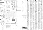
1-1. Unpacking
Check each item in the box against Figure 1-1 to make sure that you have
everything.
If any of these items are missing, contact your supplier.
Sample paper roll
76mm holders
support spacers
Ferrite core
for peripheral
unit cable
(E.U. only)
User's manual
Printer
;;
Fastener
(E.U. only)
Fig. 1-1
1-2. Locating the printer
Before you start setting up your printer, make sure that you have a suitable place
in which to locate it. By “a suitable place”, we mean:
• Close to an easily accessible socket-outlet.
• A firm, level surface which is fairly vibration-free
• Away from excessive heat (such as direct sunlight, heaters, etc)
• Away from excessive humidity
• Away from excessive dust
• With access to a steady power supply that is not subject to power surges. For
example, do not connect the printer to the same circuit as a large, noiseproducing appliance such as a refrigerator or an air conditioner.
NOTE: Make sure that the line voltage is the voltage specified on the printer’s
identification plate.
–1–
ENGLISH
1. Unpacking and Inspection
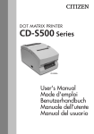
2. Parts Identification and Nomenclature
ENGLISH
Cover
Protects the printer from
dust and reduces noise.
Do not open the cover
while printing.
Control panel
Features two control
switches and two
indicators to indicate
printer status.
Power switch
Turns printer
power on and off.
AC adapter cable connector
For connection of the AC adapter.
Never unplug the AC adapter
while the printer is on.
Interface connector
Connects the printer
with host computer.
Peripheral unit drive circuit connector
Connects to peripheral units such
as cash drawers, etc.
Do not connect this to a telephone.
Fig. 2-1 External view of the printer
–2–
Please prepare the following before making connections to the printer. Always
have the power switch in the off position when making any connections.
• Interface cable
• Ferrite core (E.U. only)
• Optional AC adapter
3-1. Interface Cable
1 Open the cover
2 Push the head up lever (green) to the
rear.
Head-up
lever
Caution
If the printer is to be shipped, or if it
is to be stored for an extended period
of time, always pull the head up lever
forward so that the printer head is in
the up position. This will protect the
thermal head and prevent deformation of the platen.
Feed knob
[Head-up position] [Head-closed position]
3 Close the cover.
–3–
ENGLISH
3. Printer Connection
ENGLISH
4 Plug the printer-side connector of
the interface cable into the printer
interface connector and use screws
to secure the serial interface connector or a hook bracket to secure
the parallel interface connector.
Screws
Screwdriver
–4–
3-2. Ferrite Core (Europe only)
ENGLISH
NOTE: Take special care when following the procedures listed below.
■ A ferrite core noise filter for the
peripheral unit cable comes packed
with the printer.
■ The ferrite core is normally packed
so it is opened, as shown in Fig. 3-1.
Ferrite core (28mm diameter)
;;;
Fastener
• Pass the fastener through the ferrite
core.
Fig. 3-3
One loop
Pull and cut
Fig. 3-1
If you find that the ferrite core is not
opened: Use a pointed object to pry
the plastic lock of the ferrite core
apart, as shown in Fig. 3-2. When
opening it, take care not to damage
the ferrite core or the plastic lock.
• Pass the fastener around the cable
and lock it.
Cut off the excess with a pair of scissors.
Fig. 3-4
Fig. 3-2
–5–
■ Clamp the ferrite core onto the peripheral unit cable, looping the cable as
shown in Fig. 3-1.
ENGLISH
• When installing the ferrite core be careful not to damage the cable.
• The ferrite core should be anchored firmly in place with the fastener that
comes with it, as shown in Fig. 3-3 and Fig. 3-4.
• Do not forget to loop the cable.
Fastener
One loop
Connector
Ferrite core
Screw M3×4
Separate ground wire
Peripheral unit drive
circuit connector
Fig. 3-5
–6–
NOTE: Before connecting/disconnecting the AC adapter, make sure that power
to the printer and all the devices connected to the printer is turned off.
Also make sure the power cable plug is disconnected from the AC outlet.
1 Connect the AC adapter to the power cable.
Note: Use only the standard AC adapter and power cable.
2 Connect the AC adapter to the connector on the printer.
3 Insert the power cable plug into an AC outlet.
Fig. 3-6
–7–
ENGLISH
3-3. Optional AC Adapter
4. Near-End Sensor
ENGLISH
This printer is equipped with a sensor that detects when a roll of paper is near the
end. Read the following if you are going to use this sensor.
1 Open the cover.
2 Refer to the table below and set the
detection position for the diameter
of the roll being used.
Roll Diameter
Position
Approx. 22mm
Approx. 26mm
Approx. 30mm
Adjustment
Step 1
Step 2
Step 3
3 Move the sensor and adjust the
guraduation of the sensor to the
adjusted position that corresponds
to the diameter of the roll selected.
Press this hole with a ball point pen or
similar pointed object and slide it into
position. Make sure that the protruding
section (shown by arrow) is securely in
the groove, especially at step 2.
Cautions
1) The factory setting is step 1.
2) Always use a paper roll with a core that has an inside diameter of 12 mm and
an outside diameter of 18 mm in order to ensure proper detection of the
remaining paper amount.
3) The near-end sensor is disabled when shipped from the factory. It can be
enabled by rewriting the memory switch. Refer to the “Programmer’s
Manual” for details.
–8–
5-1. Loading Paper
1 Procure a roll of paper and fold in
the corners as shown in the illustration.
2 Open the printer cover.
Paper roll
3 Open the holder lever by pressing it
in the direction indicated by the
arrow. Load the paper in the direction shown in the illustration. Make
sure that the core of the paper roll is
held securely by the holder.
Core
Holder
Holder lever
–9–
ENGLISH
5. Loading Paper
ENGLISH
Paper feeder
Paper guide
Paper exit
Support guide
Auto cutter
unit
4 (Using the auto loading function)
• With the auto cutter installed.
1) The unit is shipped with the head-up
lever in the up position. Press the
lever back to put it in the closed
position. See “Chapter 3: Printer
Connection” for details.
2) Insert the edge of the paper into the
paper feeder. If inserted correctly,
the edge of the paper will pass
through the paper exit.
Head-up lever
Feed knob
Feed switch
Auto cutter unit
Caution
If the paper is not completely straight
when it is inserted into the unit, the
paper will “skew” *1) and the edges
will fold. Depending upon the degree
of the skew, the flow of paper can be
automatically corrected by pressing
the FEED switch *2) to adjust the
flow of paper. However, should the
paper become extremely skewed, a
paper jam may occur. To clear the
jam, pull the auto cutter unit all the
way back in the direction indicated
by the arrow until the lock engages.
With the lever in the “head-up” position, pull out the paper from the paper
feeder.
*1) Skew: When paper is fed unevenly
into the printer.
*2) See “Chapter 6: Control Panel” for
details on operating the FEED
switch.
– 10 –
Paper exit
Printer mechanism
Caution
If the paper is not completely straight when it is inserted into the unit, the paper
will “skew” and the edges will fold. Depending upon the degree of the skew,
the flow of paper can be automatically corrected by pressing the FEED switch.
However, should the paper become extremely skewed, a paper jam may occur.
To clear the jam, pull the head-up lever forward. With the lever in the “headup” position, pull out the paper from the paper feeder.
Auto cutter unit
5 (Manual loading)
1) Move the auto cutter unit all the way
back in the direction indicated by
the arrow until the lock engages
(unnecessary if an auto cutter unit is
not installed).
2) Pull the head-up lever forward into
the “head-up” position. The headup lever is shipped from the factory
in the “head-up” position.
See “Chapter 3: Printer Connection” for details.
3) Insert the edge of the paper into the
paper feeder. Turn the feed knob
(green) until the edge of the paper
passes through the printer mechanism’s paper exit.
– 11 –
ENGLISH
• Without an auto paper cutter.
1) Same as 4-1.
2) Insert the edge of the paper into the
paper feeder. If inserted correctly,
the edge of the paper will pass
through the paper exit.
Paper feeder
ENGLISH
4) Once the paper has passed through
the printer mechanism’s paper exit,
pull the paper straight to correctly
position it.
5) Make sure that the paper is straight
with approximately 15-20 centimeters
exposed and lower back the head-up
cutter.
6) Take the edge of the paper and cut it
by pressing it up against the head.
Be careful not to cut yourself on the
edge of the auto cutter unit during
this step.
7) Close the auto cutter unit (unnecessary if an auto cutter unit is not
installed).
8) Close the cover, turn on the ON
LINE switch and make sure that the
ON LINE indicator turns on.
See “Chapter 6: Control Panel” for
details on the ON LINE indicator
and switch.
Caution
When using the auto loading function, part of the paper will be exposed
after loading. Be sure to pass this
length of the paper through the paper
exit of the printer cover before closing the cover.
When loading paper manually, make
sure that paper has passed through
the paper exit of the printer cover
after closing the cover and pressing
the FEED switch.
– 12 –
1 When the paper sensor detects that
the printer is out of paper, press the
FEED switch until the paper feeding action stops. If the near-end
sensor is operating and there is still
paper on the roll, cut the paper just
in front of the paper feeder and press
the FEED switch until the paper
feeding action stops. See “Chapter
4: Near-end Sensor” for details.
2 Open the cover, pull the head-up
lever forward into the “head-up”
position and pull out the paper.
3 Open the holder lever in the direction indicated by the arrow and remove the core and any left over
paper.
4 See “5-1: Loading Paper” and follow the directions provided to refill
the paper supply.
– 13 –
ENGLISH
5-2. Refilling the Paper Supply
5-3. 76mm Width Support
ENGLISH
76mm width support is an available accessory when adding to or changing the
configuration of the printer.
76mm holders
Support spacers
1 Open the printer cover.
80mm holders
M2 screw
Upper case
76mm holders
2 Use a screwdriver to remove the
M2 screws that fasten the 80mm
holders to the upper case and the
holder lever. Replace the 80mm
Holder lever
holders with the optional 76mm
M2 screw
holders.
Caution
Be careful not to drop any of the
screws.
– 14 –
3 Move the auto cutter unit in the
direction of the arrow until the lock
engages (unnecessary if an auto
cutter unit is not installed).
Support spacer
4 Insert the support spacers for 76mm
paper into the inner left and right
sides of the support guides as shown
in the illustration. Make sure that
the catches on the support spacers
lock onto the holes in the support
guides.
Where the catch locks
5 Close the auto cutter unit (unnecessary if an auto cutter unit is not
installed).
– 15 –
ENGLISH
Auto cutter unit
5-4. Clearing Paper Jams
ENGLISH
1 Turn the power to the printer OFF and open the cover.
2 Move the auto cutter unit in the direction of the arrow until the lock engages
(unnecessary if an auto cutter unit is not installed).
3 Cut some of the paper from the roll just in front of the paper feeder to clear the
paper jam.
4 Using the same procedure described for cleaning the head, push the head-open
lever back and release the set cover to enable the head-open position. See
“Appendix E: Cleaning” for details.
5 Clear away the jammed paper. If the jammed paper cannot be reached, turn the
feed knob and remove the paper.
6 Once the paper jam has been removed, press the top of the set cover and engage
the head-open lever.
Cautions
* If a paper jam should occur in the auto cutter, place a screwdriver into the
opening located on the upper right surface of the auto cutter unit; using the
screwdriver, turn the knob to move the blade and remove the jammed paper.
* Certain parts of the printer, especially the metal fixtures, can cause injuries if
handled improperly. Please be careful when handling the printer.
Auto cutter unit
Opening
Knob
– 16 –
6-1. Power ON
Operating Panel
Paper - Yes
POWER
ON LINE
1 2 3
FEED
1 Power Lamp (Green LED)
2 On-Line Lamp (Green LED)
3 On-Line Switch
4 Feed Switch
4
Paper - No
POWER
ON LINE
FEED
When the power switch is turned on, the Power Lamp and On-Line Lamp will
come on. If there is no paper, the Power Lamp will flash at approximately one
second intervals.
ON LINE Switch Indicator (Star mode only)
Used to switch between the off-line and on-line modes.
The ON LINE indicator turns on when the printer is on-line.
When the printer is off-line, printing will stop and data from the host computer
cannot be received.
FEED Switch
Each press of the FEED switch feeds paper through the printer one line at a time.
Paper is fed continuously when the FEED switch is pressed and held.
The functions of the FEED switch are supported by both the on-line and off-line
modes.
Power Indicator
The power indicator turns on when power is being supplied to the printer.
– 17 –
ENGLISH
6. Control Panel
6-2. Combined Control Panel Operations
The following settings can be made when the power switch is set to on.
ENGLISH
1 Test print
The buzzer will beep when the FEED switch is pressed and held while the
power is turned on.
– 18 –
– 19 –
ENGLISH
2 HEX dump
The buzzer will beep when the ON LINE switch is pressed and held while the
power is turned on.
6-3. Errors
1) Automatic Recovery (Power Lamp: Flashing; On-Line Lamp: On)
ENGLISH
Error Description
Abnormal head
temperature
Power Lamp Flashing Pattern
Approx. 1 Sec
Approx. 1 Sec
Recovery Conditions
Automatic recovery after head
temperature lowers.
2) Recoverable Errors (Power Lamp: Flashing; On-Line Lamp: Off)
Error Description
Power Lamp Flashing Pattern
No paper
Approx. 1 Sec
Head up
Paper near end of
roll
Cover is open
Error during paper
cutting
Approx. 1 Sec
Approx. 250 ms
Approx. 2 Sec
Approx. 250 ms
Approx. 2 Sec
Insert paper and press on-line
switch. (Star)
Insert paper and close cover. (ESC/
POS)
Lower head and press on-line
switch. (Star)
Lower head and close cover. (ESC/
POS)
Press on-line switch and printing
will continue. Both lamps light
when printing and power lamp
flashes and on-line lamp lights
when on-line. (Star)
Same as “No paper”. (ESC/POS)
Close cover and press on-line
switch. (Star)
Close cover. (ESC/POS)
Approx. Approx.
500 ms 500 ms
Approx. 125 ms
Recovery Conditions
Approx. 125 ms
If the blade is at the home position,
press on-line switch to continue
printing. If the blade is not at the
home position, it is not a recoverable error. (Star)
Command (ESC/POS)
3) Fatal Error (Power Lamp: Flashing; On-Line Lamp: Flashing) the unit
will have to be repaired.
– 20 –
P: 50ms
Pi: 100ms
1 On-line/off-line
2 No paper error
3 Head-up error
4 Paper near-end sensor error
5 Cover open error
6 Cutter error
7 Command buzzer
P
PPPP PPPP
PiPiPi
PP PP
PPPP
Pi PPP PPiPiP PPPPPi PiPiPiPiPi PiPiPiPiPi
Pi
– 21 –
ENGLISH
6-4. Buzzer Indicators (Star Mode Only)
7. Cautions
ENGLISH
7-1. Operating Cautions
1 The service life of the thermal print head cannot be guaranteed if any paper
other than the recommended paper is used. There will be a noticeable decline
in the service life of the thermal element of the print head when the paper used
contains (Na+, K++, CI-).
2 Never print when there is water or any form of moisture, such as from
condensation, on the surface of the print head.
7-2. Safety Cautions
1 Never touch the thermal print head or motor during printing or immediately
after printing as these components are very hot.
2 Never touch any moving parts, such as gears or knobs, during printing.
3 Always use care near the edges of printer components, especially metal
components, as they may cause injury.
– 22 –
8. Command summary
ENGLISH
8-1. Star Mode
Commands to Select Characters
Control codes
Hexadecimal
codes
Function
<ESC> “R” n
1B 52 n
Select international character set
<ESC> “/” “1”
<ESC> “/” <1>
1B 2F 31
1B 2F 01
Select slash zero
<ESC> “/” “0”
<ESC> “/” <0>
1B 2F 30
1B 2F 00
Select normal zero
<ESC> “b” n1 n2 n3 n4 1B 62 n1 n2 n3 n4
d1 ... <RS>
d1 ... 1E
Select bar code printing
<ESC> “M”
1B 4D
Select 12-dot pitch printing
<ESC> “p”
1B 70
Select 14-dot pitch printing
<ESC> “P”
1B 50
Select 15-dot pitch printing
<ESC> “:”
1B 3A
Select 16-dot pitch printing
<ESC> <SP> n
1B 20 n
Set character spacing
<SO>
0E
Sets the printing magnified double in
character width.
<DC4>
14
Resets the printing magnified in
character width.
<ESC> “W” n
1B 57 n
Sets the magnification rate in character width.
<ESC> <SO>
1B 0E
Sets the printing magnified double in
character height.
<ESC> <DC4>
1B 14
Resets the printing magnified in character
height.
<ESC> “h” n
1B 68 n
Sets the magnification rate in character height.
<ESC> “i” n1 n2
1B 69 n1 n2
Sets the magnification rates in character
width and height.
<ESC> “–” “1”
<ESC> “–” <1>
<ESC>“–” “0”
<ESC> “–” <0>
1B 2D 31
1B 2D 01
Select underlining
1B 2D 30
1B 2D 00
Cancel underlining
<ESC> “_” “1”
<ESC> “_” <1>
1B 5F 31
1B 5F 01
Select overlining
<ESC> “_” “0”
<ESC> “_” <0>
1B 5F 30
1B 5F 00
Cancel overlining
– 23 –
Control codes
Hexadecimal
codes
Function
ENGLISH
<ESC> “4”
1B 34
Select highlight printing
<ESC> “5”
1B 35
Cancel highlight printing
<SI>
0F
Inverted printing
<DC2>
12
Cancel inverted printing
<ESC> “E”
<ESC> “G”
1B 45
1B 47
Select emphasized printing
<ESC> “F”
<ESC> “H”
1B 46
1B 48
Cancel emphasized printing
Commands to Set the Page Format
Control codes
Hexadecimal
codes
Function
<ESC> “C” n
1B 43 n
Set page length in lines
<ESC> “C” <0> n
1B 43 00 n
Set page length in inches
<ESC> “N” n
1B 4E n
Set bottom margin
<ESC> “O”
1B 4F
Cancel bottom margin
<ESC> “l” n
1B 6C n
Set left margin
<ESC> “Q” n
1B 51 n
Set right margin
Commands to Move the Print Position
Control codes
Hexadecimal
codes
Function
<LF>
0A
Line feed
<CR>
0D
Carriage Return
<ESC> “a” n
1B 61 n
Feed paper n lines
<FF>
0C
Form feed
<HT>
09
Horizontal tab
<VT>
0B
Vertical tab
<ESC> “z” “1”
<ESC> “z” <1>
1B 7A 31
1B 7A 01
Set line spacing to 4 mm
<ESC> “0”
1B 30
Set line spacing to 3 mm
<ESC> “J” n
1B 4A n
One time n/4 mm feed
<ESC> “j” n
1B 6A n
One time n/4 mm backfeed
<ESC> “B” n1 n2 ... <0> 1B 42 n1 n2 ... 00
Set vertical tab stops
<ESC> “D” n1 n2 ... <0> 1B 44 n1 n2 ... 00
Set horizontal tab stops
– 24 –
Commands to Print Dot Graphics
Control codes
Hexadecimal
codes
<ESC> “K” n <0>
m1 m2 ...
1B 4B n 00 m1 m2
...
<ESC> “L” n1 n2
m1 m2 ...
1B 4C n1 n2 m1 m2 Print high density graphics
...
<ESC> “k” n <0> m1 ...
1B 6B n 00 m1 ...
Print normal density graphics
Print fine density graphics
Commands to Print Download Characters
Control codes
Hexadecimal
codes
<ESC> “&” “1” “1”
n m1 m2 ... m48
1B 26 31 31 n
m1 m2 ... m48
<ESC> “&” <1> <1>
n m1 m2 ... m48
1B 26 01 01
n m1 m2 ... m48
<ESC> “&” “1” “0” n
1B 26 31 30 n
<ESC> “&” <1> <0> n
1B 26 01 00 n
<ESC> “%” “1”
<ESC> “%” <1>
1B 25 31
1B 25 01
Enable download character set
<ESC> “%” “0”
<ESC> “%” <0>
1B 25 30
1B 25 00
Disable download character set
Function
Define download character
Delete a download character
Commands to Control Peripheral Devices
Control codes
Hexadecimal
codes
<ESC> <BEL> n1 n2
1B 07 n1 n2
Define drive pulse width for peripheral
device #1
<BEL>
07
Control peripheral device #1
<FS>
1C
Control peripheral device #1 immediately
<EM>
19
Control peripheral device #2 immediately
<SUB>
1A
Control peripheral device #2 immediately
Function
– 25 –
ENGLISH
Function
Commands to Control Auto Cutter
ENGLISH
Control codes
Hexadecimal
codes
<ESC> “d” “0”
<ESC> “d” <0>
<ESC> “d” “1”
<ESC> “d” <1>
<ESC> “d” “2”
<ESC> “d” <2>
<ESC> “d” “3”
<ESC> “d” <3>
1B 64 30
1B 64 00
1B 64 31
1B 64 01
1B 64 32
1B 64 02
1B 64 33
1B 64 03
Function
Full-cut command to the auto cutter
Partial-cut command to the auto cutter
Feed paper to the cutting position and perform a full-cut.
Feed paper to the cutting position and perform a partial-cut.
Other Commands
Control codes
Hexadecimal
codes
Function
<CAN>
18
Cancel last line & Initialize printer
<DC3>
13
Deselect printer
<DC1>
11
Set select mode
<RS>
1E
Beep the buzzer
<ESC> “#N, n1 n2 n3 n4” 1B 23 N 2C n1 n2 n3 n4
Set memory switch
<LF> <NUL>
0A 00
<ESC> “@”
1B 40
<ENQ>
05
<ESC> “?” <LF> <NUL> 1B 3F 0A 00
Initialize printer
Enquiry
Reset printer hardware
– 26 –
Control Code
Hexadecimal Code
Function
HT
LF
FF
DLE EOT
DLE ENQ
CAN
ESC FF
ESC SP
ESC !
ESC #
ESC $
ESC %
ESC &
ESC
ESC ESC 2
ESC 3
ESC =
ESC ?
ESC @
ESC D
ESC E
09
0A
0C
10
10
18
1B
1B
1B
1B
1B
1B
1B
1B
1B
1B
1B
1B
1B
1B
1B
1B
FF
20
21
23
24
25
26
2A
2D
32
33
3D
3F
40
44
45
Horizontal tab
Print line feed
Page mode print and return
Real time transmission of status
Real time request to printer
Cancel print data in page mode
Print page mode data
Set right space amount of character
Universal print mode designation
Set memory switch
Designate absolute printing
Designate/cancel download character set
Define download characters
Designate bit image mode
Designate/cancel underline
Set 1/6 inch line feed amount
Set line feed amount
Select peripheral equipment
Delete download characters
Initialize printer
Set horizontal tab position
Designate/cancel emphasized print
ESC G
ESC J
ESC L
ESC R
ESC S
ESC T
ESC V
ESC W
ESC \
ESC a
ESC c4
ESC c5
ESC d
ESC i
ESC p
ESC t
1B
1B
1B
1B
1B
1B
1B
1B
1B
1B
1B
1B
1B
1B
1B
1B
47
4A
4C
52
53
54
56
57
5C
61
63
63
64
69
70
74
Designate/cancel double print
Print and paper feed
Select page mode
Select international characters
Select standard mode
Select character print direction in print mode
Designate/cancel 90° character rotation
Set print range in page mode
Designate relative position
Align position
Select no valid paper detector at print stop
Enable/disable panel switch
Print and paper feed “n” lines
Partial cut (one section remaining)
Designate pulse generation
Select character code table
*
04
05
34
35
– 27 –
ENGLISH
8-2. ESC/POS Mode
Control Code
Hexadecimal Code
ENGLISH
ESC u
ESC v
ESC {
GS !
GS $
1B
1B
1B
1D
1D
75
76
7B
21
24
GS
GS /
GS :
GS B
GS H
GS I
GS L
GS P
GS V
GS W
GS \
*
1D
1D
1D
1D
1D
1D
1D
1D
1D
1D
1D
2A
2F
3A
42
48
49
4C
50
56
57
5C
GS ^
GS a
GS f
GS h
GS k
GS r
GS w
1D
1D
1D
1D
1D
1D
1D
5E
61
66
68
6B
72
77
Function
Transmission of peripheral equipment status
Transmission of paper detection status
Designate/cancel inverted printing
Designate character size
Designate absolute position of vertical direction of
characters in page mode
Define download bit image
Print download bit image
Start/finish macro definition
Designate/cancel reverse printing
Select print position of HRI characters
Printer ID transmission
Set left margin
Set basic calculated pitch
Paper cut
Set print range
Designate the relative position of vertical characters when
printing in the page mode
Execute macro
Enable/disable automatic status transmission
Select HRI character font
Set bar code height
Printing of bar code
Transmission of status
Set lateral size of bar code
– 28 –
Table des matières
2. Identification des pièces et nomenclature ............................................ 32
3. Connexion de l’imprimante ................................................................. 33
3-1. Câble d’interface ........................................................................ 33
3-2. Tore de ferrite *Uniquement pour l’Europe .............................. 35
3-3. l’adaptateur secteur optionnel .................................................... 37
4. Capteur de fin de rouleau .................................................................... 38
5. Mise en place du papier ....................................................................... 39
5-1. Mise en place du papier ............................................................. 39
5-2. Changement de rouleau de papier .............................................. 43
5-3. Support de 76 mm de large ........................................................ 44
5-4. Correction des bourrages de papier ............................................ 46
6. Tableau de commande ......................................................................... 47
6-1. Mise sous tension ....................................................................... 47
6-2. Opérations combinées du panneau de commande ..................... 48
6-3. Erreurs ........................................................................................ 50
6-4. Indications de la sonnerie (mode Star seulement) ..................... 51
7. Precautions .......................................................................................... 52
7-1. Précautions relatives à l’utilisation ............................................ 52
7-2. Précautions relatives à la sécurité .............................................. 52
8. Resume des commandes ...................................................................... 53
8-1. Mode Star ................................................................................... 53
8-2. Mode ESC/POS.......................................................................... 57
L’appendice n’est pas traduit.
FRANÇAIS
1. Déballage et inspection ........................................................................ 31
1-1. Déballage ................................................................................... 31
1-2. Emplacement de l’imprimante ................................................... 31
1. Déballage et inspection
1-1. Déballage
Echantillon de
rouleau de papier
Supports de
76mm
Pièce d'écartement
du support
Tore de ferrite
pour câble
d’appareil
périphérique
(uniquement pour
l’Europe)
Guide d’utilisation
Imprimante
;;
Attache
(uniquement
pour l’Europe)
Figure 1-1
1-2. Emplacement de l’imprimante
Avant d’entamer l’installation de l’imprimante, s’assurer que le futur emplacement est approprié. En d’autres termes, il convient que cet emplacement soit:
• à proximité d’une prise secteur d’accès aisé;
• une surface stable et de niveau non-soumise à des vibrations excessives;
• à l’abri de températures excessivement élevées (à la lumière directe du soleil,
à proximité d’appareils de chauffage, etc.)
• à l’abri de toute humidité excessive;
• à l’abri d’une quantité excessive de poussière;
• alimenté par une source secteur non-soumise à de brusques variations de
tension. Ainsi, ne pas alimenter l’imprimante via un circuit alimentant déjà un
gros consommateur de courant et producteur de bruit tel qu’un réfrigérateur
ou un climatiseur.
N.B.: S’assurer que la tension du secteur correspond bien à la tension spécifiée
par le fabricant sur la plaque d’identification de l’imprimante.
– 31 –
FRANÇAIS
Contrôler à l’aide de la figure 1-1 ci-dessous que chaque élément décrit se trouve
dans la boîte.
Si tout élément semble manquer, contacter le fournisseur.
2. Identification des pièces et nomenclature
FRANÇAIS
Capot
Protège l'imprimante contre
la poussière et réduit le bruit.
Ne pas ouvrir le capot
pendant l'impression.
Tableau de commande
Ce tableau comprend
deux commandes et deux
témoins indiquant l'état de
l'imprimante.
Interrupteur
d’alimentation
Cet interrupteur vous permet
de mettre l’imprimante sous
tension et hors tension.
Connecteur de câble
d’adaptateur secteur
Ce connecteur vous permet de
connecter le câble de l’adaptateur
secteur. Ne déconnectez pas le
câble lorsque l’imprimante est
sous tension.
Connecteur d'interface
Ce connecteur permet de
raccorder l'imprimante à
l'ordinateur-hôte.
Connecteur de circuit d'entraînement
d'appareil périphérique
Ce connecteur permet de raccorder
l'imprimante à des appareils périphériques
tels que des caisses enregistreuses, etc.
Ne pas connecter l'imprimante à un téléphone.
Figure 2-1 Vue externe de l’imprimante
– 32 –
Préparer les éléments suivants avant d’effectuer les connexions à l’imprimante.
Avant d’effectuer toute connexion, toujours veiller à ce que l’imprimante soit
hors tension.
• Câble d’interface
• Tore de ferrite (uniquement pour l’Europe)
• Adaptateur secteur en option
3-1. Câble d’interface
1 Ouvrir le capot.
2 Pousser le levier vert de la tête de
l’imprimante vers l’arrière.
Levier de tête Bouton
d'imprimante d’avance
[Tête en position haute] [Tête en position basse]
Attention
Si l’imprimante doit être expédiée ou
rangée pour une période prolongée,
s’assurer de toujours tirer le levier
vert de la tête de l’imprimante vers
l’avant afin d’amener la tête d’impression en position supérieure. Ceci
permet de protéger la tête thermique
et d’éviter toute déformation de la
plaque d’impression.
3 Fermer le capot.
– 33 –
FRANÇAIS
3. Connexion de l’imprimante
4 Raccorder le connecteur du câble
d’interface dans le connecteur pour
interface de l’imprimante et fixer le
connecteur de l’interface en série à
l’aide de vis ou le connecteur de
l’interface parallèle à l’aide des agrafes prévues.
FRANÇAIS
Vis
Screws
Screwdriver
Tournevis
– 34 –
3-2. Tore de ferrite *Uniquement pour l’Europe
N.B.:
Effectuer les démarches ci-dessous avec un soin particulier.
■ Le tore de ferrite est normalement
ouvert à la livraison, comme le montre la figure 3-1.
Attache
Fastener
;;;
Ferrite
core (28
(28mm
Tore
de ferrite
mm diameter)
de diamètre)
• Faire passer l’attache par le tore de
ferrite.
Figure 3-3
Pulletand
cut
Tirer
couper
One
loop
Une
boucle
Figure 3-1
Si ce n’est pas le cas, débloquer le
système de verrouillage en plastic
du tore de ferrite à l’aide d’un objet
pointu de la manière illustrée (3-2).
Prendre garde de ne pas abîmer le
système de verrouillage lors de
l’ouverture de ce dernier.
• Faire passer l’attache autours du
câble et la bloquer.
Couper la partie de l’attache ressortant
du mécanisme de blocage à l’aide d’une
paire de ciseaux.
Figure 3-4
Figure 3-2
– 35 –
FRANÇAIS
■ L’imprimante est fournie avec un
filtre antibruit à tore de ferrite destiné au câble de l’appareil périphérique.
■ Serrer le tore de ferrite autours du câble d’appareil périphérique en effectuant
une boucle de la manière illustrée (3-1).
• Veiller à ne pas endommager le câble lors de l’installation du tore de ferrite.
• Le tore de ferrite doit être correctement fixé à l’aide de l’attache fournie (se
reporter aux figures 3-3 et 3-4).
• Veiller à ne pas oublier de faire une boucle dans le câble.
FRANÇAIS
Fastener
Attache
Une
One boucle
loop
Connecteur
Connector
Tore decore
ferrite
Ferrite
Vis M3
×4
Screw
M3×4
Fil de masse
séparé
Separate
ground
wire
Connecteur
de drive
circuit
Peripheral unit
d’entraînement
circuit connector
d’appareil périphérique
Figure 3-5
– 36 –
3-3. l’adaptateur secteur optionnel
1 Connectez l’adaptateur secteur au câble d’alimentation.
Remarque:Utilisez exclusivement l’adaptateur secteur et le câble d’alimentation destinés à l’imprimante.
2 Connectez l’adaptateur à la borne de l’imprimante.
3 Branchez la prise du câble d’alimentation à la prise secteur.
Interrupteur
d'alimentation
Figure 3-6
– 37 –
FRANÇAIS
Remarque:Avant de connecter ou déconnecter l’adaptateur secteur, veillez
à ce que l’imprimante et tous les appareils qui y sont connectés
soient hors tension. Veillez également à débrancher le câble
d’alimentation de la prise secteur.
4. Capteur de fin de rouleau
FRANÇAIS
Cette imprimante est équipée d’un capteur détectant l’approche de la fin de
rouleau. Pour savoir comment utiliser cette fonction, lire les instructions cidessous.
1 Ouvrir le capot.
2 Régler la position de détection en
fonction du diamètre du rouleau de
papier utilisé à l’aide du tableau cidessous.
Diamètre de
rouleau
Environ 22 mm
Environ 26 mm
Environ 30 mm
Position
Cran 1
Cran 2
Cran 3
3 Déplacer le capteur jusqu’au cran
correspondant au diamètre du rouleau employé.
Introduire la pointe d’un stylo à bille ou
d’un objet pointu similaire dans l’orifice du capteur et faire glisser ce dernier jusqu’au cran approprié. S’assurer
que l’ergot du capteur (indiqué par la
flèche sur la figure ci-contre) est correctement inséré dans le cran, tout spécialement s’il s’agit du cran 2.
Attention
1) Le capteur de fin de rouleau est positionné sur le cran 1 à la sortie d’usine.
2) Afin d’assurer une détection correcte de la quantité de papier restant sur le
rouleau, toujours employer un rouleau de papier dont les diamètres interne
et externe du rouleau de carton correspondent respectivement à 12 mm et 18
mm.
3) Le capteur de fin de rouleau n’est pas activé à la sortie d’usine. Il convient
de l’activer en modifiant le commutateur de mémorisation. Pour plus de
détails, se reporter au “Manuel du Programmeur”.
– 38 –
5. Mise en place du papier
1 Seprocurerunrouleaudepapieret
plierlescoinsdelafaçonillustrée.
2 OuvrirleCapot.
3 Ecarterlelevierdusupportenappuyant dessus dans le sens de la
flèche.Installerlerouleaudepapier
delamanièreillustréeci-contre.
S’assurerquelenoyaudurouleau
de papier est maintenu fermement
enplaceparlesupport.
Rouleau de
papier
Rouleau
Axe
Levier du support
– 39 –
FRANÇAIS
5-1. Mise en place du papier
Mécanisme
d’avance de
papier
Fente de sortie
de papier
FRANÇAIS
Mécanisme
de découpe
automatique
Guide de papier
Guide du
support
Levier de tête
d'imprimante
Touche
d’avance
Mécanisme
de découpe
automatique
Bouton
d’avance
4 (Utilisationdelafonctiondechargement automatique)
• Avec le mécanisme de découpe
automatiqueenplace.
1)L’imprimanteestlivréeaveclelevierdesoulèvementdelatêted’imprimanteenpositionhaute.Appuyer
surlelevierpourrefermerlatête.
Voir“Chapitre3:Raccordementde
l’imprimante”pourlesdétails.
2) Insérer le bord du papier dans le
mécanismed’avancedepapier.S’il
estinsérécorrectement,leborddu
papierressortiraparlafentedesortie de papier.
Attention
Si le papier n'est pas inséré dans l'imprimante parfaitement droit, il se "mettra
en travers" *1) et les bords se plieront.
Suivant l’angle pris par le papier, il est
possible que l'avance du papier puisse
être corrigée automatiquement en appuyant sur la touche d’avance FEED
*2) pour la réguler. Néanmoins, si le
papier prend un angle trop important,
un bourrage de papier surviendra. Pour
corriger le bourrage de papier, tirer
complètement le mécanisme de découpe automatique dans le sens de la
flèche jusqu'à ce qu'il se verrouille.
Avec le levier de la tête en position
haute, tirer le papier à l'extérieur du
mécanisme d'avance de papier.
*1) Mise en travers : Quand le papier
est entraîné irrégulièrement dans
l’imprimante.
*2) Voir "Chapitre 6 : Tableau de commande" pour des détails sur le fonctionnement de la touche d’avance
FEED.
– 40 –
Fente de sortie
de papier
• Sans mécanisme de découpe
automatique.
1) Comme pour 4-1.
2) Insérer le bord du papier dans le
mécanisme d’avance de papier. Si
lepapierestinsérécorrectement,le
borddupapierressortiraparlafente
de sortie de papier.
Mécanisme
d’impression
Attention
Silepapiern’estpasinsérédansl’imprimanteparfaitementdroit,ilse“mettra
entravers”etlesbordsseplieront.Suivantl’angleprisparlepapier,ilest
possiblequel’avancedupapierpuisseêtrecorrigéeautomatiquementsivous
appuyezsurlatouched’avanceFEEDpourlaréguler.Néanmoins,silepapier
prendunangletropimportant,unbourragedepapiersurviendra.Pourdégager
lebourragedepapier,tirerlelevierdesoulèvementdelatêted’imprimantevers
l’avant.Aveclelevierdelatêteenpositionhaute,tirerlepapieràl’extérieur
du mécanisme d’avance de papier.
Mécanisme de découpe
automatique
5 (Chargement manuel)
1) Tirer complètement le mécanisme
dedécoupeautomatiquedanslesens
delaflèchejusqu’àcequ’ilseverrouille(ignorercetteétapesil’appareilnedisposepasdemécanisme
de découpe automatique).
2)Tirerlelevierdesoulèvementdela
têted’imprimanteversl’avantpour
mettre la tête en position haute.
L’imprimanteestlivréeaveclelevierdesoulèvementdelatêted’imprimantedanscetteposition.
Voir“Chapitre3:Raccordementde
l’imprimante”pourlesdétails.
3) Insérer le bord du papier dans le mécanisme d’avance de papier. Tourner
le bouton d’avance de papier (vert)
jusqu’à ce que le bord du papier ressorte par la fente de sortie de papier du
mécanisme d’impression.
– 41 –
FRANÇAIS
Mécanisme
d’avance de
papier
FRANÇAIS
4) Une fois que le papier est ressorti par la
fente de sortie de papier du mécanisme d’impression, tirer tout droit
sur le papier pour corriger sa position.
5)S’assurerquelepapierestbiendroit
avec environ 15 à 20 centimètres
exposés,puisabaisserlatêtequi
étaitenpositionhaute.
6)Saisirleborddupapieretlecouper
en appuyant ce dernier contre la
tête.Faireattentionànepassecoupersurlebordtranchantdumécanisme de découpe automatique.
7) Refermer le mécanisme de découpe
automatique(ignorercetteétapesi
l’appareilnedisposepasdemécanisme de découpe automatique).
8) Refermer le capot, appuyer sur le
commutateur ON LINE (en ligne)
ets’assurerqueletémoinONLINE
s’allume.
Voir“Chapitre6:Tableaudecommande”pourdesdétailssurletémoin et le commutateur ON LINE.
Attention
En cas de chargement automatique,
une partie du papier sera exposée
aprèslechargement.Veilleràfaire
passercettelongueurdepapierdans
lasortiedepapierducapotdel’imprimanteavantderefermerlecapot.
Encasdechargementmanuel,s’assurerquelepapierestpassédansla
sortiedepapierducapotdel’imprimanteaprèslafermetureducapotet
unepressionsurlatouched’avance
FEED.
– 42 –
1 Quandlecapteurdepapierdétecte
l’absencedepapierdansl’imprimante,appuyersurlatoucheFEED
jusqu’àcequel’avancedupapier
cesse. Quand le capteur de fin de
rouleauprochefonctionnealorsqu’il
restedupapiersurlerouleau,couperlepapierjusteavantlemécanisme d’avance de papier et appuyersurlatoucheFEEDjusqu’à
ce que l’avance du papier cesse.
Voir“Chapitre4:Capteurdefinde
rouleauproche”pourdesdétails.
2 Ouvrirlecapotettirerlelevierde
soulèvementdelatêted’imprimante
versl’avantpourmettrecettedernièreenpositionhaute,puistirersur
lepapierpourl’extraire.
3 Tirer le levier du support dans le
sensdelaflècheetenleverlenoyau
ettoutlepapierrestant.
4 Voir”5-1:Miseenplacedupapier:
etsuivrelesinstructionsfournies
pourchangerlerouleaudepapier.
– 43 –
FRANÇAIS
5-2. Changement de rouleau de papier
5-3. Support de 76 mm de large
Un support de 76 mm de large est disponible pour compléter ou modifier la
configurationdel’imprimante.
FRANÇAIS
Supports de 76 mm
Pièce d’écartement du support
1 Ouvrirlecapot.
Supports de 80 mm
Vis M2
Supports de 76 mm
Partie
supérieure
Levier du
support
Vis M2
2 Utiliseruntournevispourenlever
lesvisM2quiattachentlessupports de 80 mm à la partie supérieure du coffret et au levier du
support.Remplacerlessupportsde
80 mm par les supports de 76 mm en
option.
Attention
Faire attention à ne laisser tomber
aucunedesvis.
– 44 –
3 Déplacerlemécanismededécoupe
automatiquedanslesensdelaflèchejusqu’àcequ’ilseverrouille
(ignorercetteétapesil’appareilne
dispose pas de mécanisme de découpeautomatique).
Pièce d’écartement du support
Quand une encoche
s’encliquette
4Insérerlespiècesd’espacementde
support pour papier de 76 mm à
l’intérieur,descôtésgaucheetdroit
des guides du support comme indiquédansl’illustration.Veilleràce
quelesencochesdespiècesd’espacementdesupports’encliquettent
danslestrousdesguidesdesupport.
5 Refermer le mécanisme de découpe
automatique(ignorercetteétapesi
l’appareilnedisposepasdemécanisme de découpe automatique).
– 45 –
FRANÇAIS
Mécanisme de
découpe
automatique
5-4. Correction des bourrages de papier
FRANÇAIS
1 Mettrel’imprimantehorstensionetouvrirlecapot.
2 Déplacer le mécanisme de découpe automatique dans le sens de la flèche
jusqu’àcequ’ilseverrouille(ignorercetteétapesil’appareilnedisposepas
de mécanisme de découpe automatique).
3 Couperunpeudepapierdurouleaudevantlasortiedumécanismed’avance
depapierpourcorrigerlebourragedepapier.
4 Enutilisantlaprocéduredécritepourlenettoyagedelatête,pousserlelevier
desoulèvementdelatêteversl’arrièreetlibérerlecachepourpermettre
l’ouverturedelatête.Voir“AppendiceE:Nettoyage”pourdesdétails.
5 Corriger le bourrage de papier. Si cela est impossible, tourner le bouton
d’avanceetretirerlepapier.
6 Unefoislebourragedepapiercorrigé,appuyersurledessusducachedesorte
àbloquercederniervialesleviersd’ouverturedelatêtedel’imprimante.
Attention
* Siunbourragedepapiersurvientdanslemécanismededécoupeautomatique,
inséreruntournevisdansl’ouverturesetrouvantsurlasurfacesupérieure
droite du mécanisme de découpe automatique; en utilisant le tournevis,
tournerleboutonpourdéplacerlalameetenleverlepapiercoincé.
* Certainespartiesdel’imprimante,enparticulierlespiècesmétalliques,
peuventprovoquerdesblessuressiellessontmanipuléesdefaçonincorrecte.
Fairetrèsattentionpourlamanipulationdel’imprimante.
Mécanisme
de découpe
automatique
Ouverture
Bouton
– 46 –
6. Tableau de commande
6-1. Mise sous tension
Papier chargé
POWER
ON LINE
1 2 3
FEED
4
1 Témoin d’alimentation POWER
(DEL verte)
2 Témoin ON LINE (en ligne) (DEL
verte)
3 Commutateur ON LINE (en ligne)
4 Touche d’avance FEED
Pas de papier chargé
POWER
ON LINE
FEED
Lorsque l’imprimante est mise sous tension, les témoins d’alimentation POWER
et ON LINE (en ligne) s’allument. Si l’imprimante ne contient pas de papier, le
témoin POWER clignote à intervalles d’environ une seconde.
Témoin de commutateur ON LINE (mode Star seulement)
Utiliser pour commuter entre les modes hors ligne et en ligne.
Le témoin ON LINE s’allume quand l’imprimante est en ligne.
Quand l’imprimante est hors ligne, L’impression s’arrête et les données de
l’ordinateur hôte ne peuvent pas être reçues.
Touche d’avance FEED
A chaque pression sur la touche d’avance FEED, le papier avance dans l’imprimante une ligne à la fois. Le papier avance en continu quand vous maintenez la
touche FEED enfoncée.
Les fonctions de la touche FEED sont supportées aussi bien dans le mode en ligne
que dans le mode hors ligne.
Témoin d’alimentation POWER
Le témoin d’alimentation POWER s’allume quand l’imprimante est sous tension.
– 47 –
FRANÇAIS
Tableau de commande
6-2. Opérations combinées du panneau de commande
Les réglages suivants peuvent être effectués quand l’imprimante est sous tension.
1 Essai d’impression
Une sonnerie retentit quand la touche FEED est maintenue enfoncée alors que
l’imprimante est sous tension.
FRANÇAIS
– 48 –
FRANÇAIS
2 Vidage hexadécimal
Une sonnerie retentit quand le commutateur ON LINE est maintenue enfoncé
alors que l’imprimante est sous tension.
– 49 –
6-3. Erreurs
1) Erreurs à correction automatique (témoin POWER clignotant; témoin
ON LINE allumé)
Description de l’erreur
T° anormale de la
tête
Cycle de clignotement du témoin POWER
Environ
Approx.11sec.
Sec
Environ
Approx. 11 sec.
Sec
Correction d’erreur
Correction automatique après
baisse de la t° de la tête.
FRANÇAIS
2) Erreurs corrigibles (témoin POWER clignotant; témoin ON LINE éteint)
Description de l’erreur
Pas de papier
chargé
Tête en position
supérieure
Fin du rouleau de
papier proche
Le couvercle est
ouvert.
Erreur durant la
découpe du papier
Cycle de clignotement du témoin POWER
Environ
Approx.11sec.
Sec
Environ
Approx. 11 sec.
Sec
Approx.
Environ250
250ms
ms
Approx.
Environ 2 Sec
sec.
Approx.250
250ms
ms
Environ
Approx.
Sec
Environ 2 sec.
Abaisser la tête d’impression et
appuyer sur le commutateur ONLINE. (Star)
Abaisser la tête d’impression et
refermer le capot. (ESC/POS)
Appuyer sur le commutateur ONLINE et l’impression se poursuit.
Les deux témoins sont allumés
pendant l’impression ; le témoin
POWER clignote et le témoin ONLINE est allumé lorsque l’appareil
est en ligne. (Star)
Voir l’erreur “Pas de papier”.
(ESC/POS)
Refermer le capot et appuyer sur le
commutateur ON-LINE. (Star)
Refermer le capot. (ESC/POS)
Environ Environ
500 ms 500 ms
Approx. 125
125 ms
ms
Environ
Correction d’erreur
Insérer le papier et appuyer sur le
commutateur ON-LINE. (Star)
Insérer le papier et refermer le
capot. (ESC/POS)
Approx.
Environ125
125ms
ms
Si la lame est à sa position
d’origine, appuyer sur commutateur
ON-LINE afin de poursuivre
l’impression. Si la lame n’est pas à
sa position d’origine, l’erreur n’est
pas réparable. (Star)
Commande (ESC/POS)
3) Erreur non-corrigible (témoin POWER clignotant; témoin ON LINE
clignotant), il convient de faire réparer l’imprimante.
– 50 –
P : 50 ms Pi : 100ms
1 En ligne/hors ligne
2 Erreur pas de papier
3 Erreur tête en position haute
4 Erreur capteur de fin de rouleau proche
5 Erreur capot ouvert
6 Erreur mécanisme de découpe
7 Sonnerie de commande
P
PPPP PPPP
PiPiPi
PP PP
PPPP
Pi PPP PPiPiP PPPPPi PiPiPiPiPi PiPiPiPiPi
Pi
– 51 –
FRANÇAIS
6-4. Indications de la sonnerie (mode Star seulement)
7. Precautions
7-1. Précautions relatives à l’utilisation
FRANÇAIS
1 La durée de vie de la tête d’imprimante thermique ne peut être garantie si tout
autre papier que celui recommandé est employé. Si le papier utilisé contient
du Na+, K++, CI–, la durée de vie de l’élément thermique de la tête
d’impression sera considérablement réduite.
2 Ne jamais effectuer d’impression lorsque la surface de la tête d’impression est
couverte d’eau ou de toute forme d’humidité, telle que la condensation.
7-2. Précautions relatives à la sécurité
1 Ne jamais toucher la tête d’imprimante thermique ou le moteur durant
l’impression ou immédiatement après l’impression. En effet, ces éléments
sont alors extrêmement chauds.
2 Ne jamais toucher les éléments mobiles tels que les rouages ou les boutons
durant l’impression.
3 Les bords des éléments de l’imprimante, surtout ceux en métal, sont à manier
avec une prudence particulière. En effet, ceux-ci pourraient causer des
blessures.
– 52 –
8. Resume des commandes
8-1. Mode Star
Code de contrôle
Codes
hexadécimaux
Fonction
<ESC> “R” n
1B 52 n
Sélection du jeu de caractères internationaux
<ESC> “/” “1”
<ESC> “/” <1>
1B 2F 31
1B 2F 01
Sélection du zéro barré
<ESC> “/” “0”
<ESC> “/” <0>
1B 2F 30
1B 2F 00
Sélection du zéro normal
<ESC> “b” n1 n2 n3 n4 1B 62 n1 n2 n3 n4
d1 ... <RS>
d1 ... 1E
Sélection d’impression de code à barres
<ESC> “M”
1B 4D
Sélection d’impression de pas 12 points
<ESC> “p”
1B 70
Sélection d’impression de pas 14 points
<ESC> “P”
1B 50
Sélection d’impression de pas 15 points
<ESC> “:”
1B 3A
Sélection d’impression de pas 16 points
<ESC> <SP> n
1B 20 n
Réglage d’espacement de caractère
<SO>
0E
Réglage d’impression d’agrandissement
double de largeur de caractère
<DC4>
14
Nouveau réglage d’impression d’agrandissement
de largeur de caractère
<ESC> “W” n
1B 57 n
Réglage d’agrandissement de largeur de caractère
<ESC> <SO>
1B 0E
Réglage d’impression d’agrandissement
double de hauteur de caractère
<ESC> <DC4>
1B 14
Nouveau réglage d’impression d’agrandissement
de hauteur de caractère
<ESC> “h” n
1B 68 n
Réglage d’agrandissement de hauteur de caractère
<ESC> “i” n1 n2
1B 69 n1 n2
Réglage d’agrandissements de largeur et de
hauteur de caractère
<ESC> “–” “1”
<ESC> “–” <1>
<ESC>“–” “0”
<ESC> “–” <0>
1B 2D 31
1B 2D 01
Sélection de soulignement
1B 2D 30
1B 2D 00
Annulation de soulignement
<ESC> “_” “1”
<ESC> “_” <1>
1B 5F 31
1B 5F 01
Sélection de surlignement
<ESC> “_” “0”
<ESC> “_” <0>
1B 5F 30
1B 5F 00
Annulation de surlignement
– 53 –
FRANÇAIS
Commandes de sélection de caractères
FRANÇAIS
Code de contrôle
Codes
hexadécimaux
<ESC> “4”
1B 34
Sélection d’impression surintensifiée
<ESC> “5”
1B 35
Annulation d’impression surintensifiée
<SI>
0F
Impression inversée
<DC2>
12
Annulation d’impression inversée
<ESC> “E”
<ESC> “G”
1B 45
1B 47
Sélection d’impression mise en valeur
<ESC> “F”
<ESC> “H”
1B 46
1B 48
Annulation d’impression mise en valeur
Fonction
Commandes de réglage du format de page
Code de contrôle
Codes
hexadécimaux
Fonction
<ESC> “C” n
1B 43 n
Réglage de la longueur de page en lignes
<ESC> “C” <0> n
1B 43 00 n
Réglage de la longueur de page en pouces
<ESC> “N” n
1B 4E n
Réglage de la marge inférieure
<ESC> “O”
1B 4F
Annulation de la marge inférieure
<ESC> “l” n
1B 6C n
Réglage de la marche gauche
<ESC> “Q” n
1B 51 n
Réglage de la marge droite
Commandes de déplacement de la position d’impression
Code de contrôle
Codes
hexadécimaux
Fonction
<LF>
0A
Avance de ligne
<CR>
0D
Retour de chariot
<ESC> “a” n
1B 61 n
Avance de n lignes de papier
<FF>
0C
Saut de page
<HT>
09
Tabulation horizontale
<VT>
0B
Tabulation verticale
<ESC> “z” “1”
<ESC> “z” <1>
1B 7A 31
1B 7A 01
Réglage d’espacement de ligne à 4 mm
<ESC> “0”
1B 30
Réglage d’espacement de ligne à 3 mm
<ESC> “J” n
1B 4A n
Avance de n/4 mm à la fois
<ESC> “j” n
1B 6A n
Recul de n/4 mm à la fois
<ESC> “B” n1 n2 ... <0> 1B 42 n1 n2 ... 00
Réglage d’arrêts de tabulation verticale
<ESC> “D” n1 n2 ... <0> 1B 44 n1 n2 ... 00
Réglage d’arrêts de tabulation horizontale
– 54 –
Code de contrôle
Codes
hexadécimaux
Fonction
<ESC> “K” n <0>
m1 m2 ...
1B 4B n 00 m1 m2
...
Impression de graphiques densité normale
<ESC> “L” n1 n2
m1 m2 ...
1B 4C n1 n2 m1 m2
Impression de graphiques haute densité
...
<ESC> “k” n <0> m1 ...
1B 6B n 00 m1 ...
Impression de graphiques densité fine
Commandes d’impression de caractères téléchargés
Code de contrôle
Codes
hexadécimaux
<ESC> “&” “1” “1”
n m1 m2 ... m48
1B 26 31 31 n
m1 m2 ... m48
<ESC> “&” <1> <1>
n m1 m2 ... m48
1B 26 01 01
n m1 m2 ... m48
<ESC> “&” “1” “0” n
1B 26 31 30 n
<ESC> “&” <1> <0> n
1B 26 01 00 n
<ESC> “%” “1”
<ESC> “%” <1>
1B 25 31
1B 25 01
Validation d’un jeu de caractères téléchargés
<ESC> “%” “0”
<ESC> “%” <0>
1B 25 30
1B 25 00
Invalidation d’un jeu de caractères téléchargés
Fonction
Définition de caractère téléchargé
Suppression de caractère téléchargé
Commandes de pilotage des périphériques
Code de contrôle
Codes
hexadécimaux
<ESC> <BEL> n1 n2
1B 07 n1 n2
Définition de la largeur d’impulsion d’entraînement du périphérique #1
<BEL>
07
Pilotage du périphérique #1
<FS>
1C
Pilotage immédiat du périphérique #1
<EM>
19
Pilotage immédiat du périphérique #2
<SUB>
1A
Pilotage immédiat du périphérique #2
Fonction
– 55 –
FRANÇAIS
Commandes d’impression de graphiques en points
Commandes de pilotage du mécanisme automatique de découpe
FRANÇAIS
Code de contrôle
Codes
hexadécimaux
Fonction
<ESC> “d” “0”
<ESC> “d” <0>
1B 64 30
1B 64 00
Commande de découpe complète au mécanisme
automatique
<ESC> “d” “1”
<ESC> “d” <1>
1B 64 31
1B 64 01
Commande de découpe partielle au mécanisme
automatique
<ESC> “d” “2”
<ESC> “d” <2>
1B 64 32
1B 64 02
Avance du papier sur la position de découpe et
découpe complète du papier.
<ESC> “d” “3”
<ESC> “d” <3>
1B 64 33
1B 64 03
Avance du papier sur la position de découpe et
découpe partielle du papier.
Code de contrôle
Codes
hexadécimaux
Fonction
<CAN>
18
Annulation de la dernière ligne et initialisation
de l’imprimante
<DC3>
13
Désélection de l’imprimante
<DC1>
11
Réglage du mode de sélection
<RS>
1E
Retentissement de l’avertisseur
Autres commandes
<ESC> “#N, n1 n2 n3 n4” 1B 23 N 2C n1 n2 n3 n4
Réglage du commutateur de mémorisation
<LF> <NUL>
0A 00
<ESC> “@”
1B 40
<ENQ>
05
<ESC> “?” <LF> <NUL> 1B 3F 0A 00
Initialisation de l’imprimante
Interrogation
Initialisation de l’imprimante
– 56 –
8-2. Mode ESC/POS
Code hexadécimal
HT
LF
FF
DLE EOT
DLE ENQ
CAN
ESC FF
ESC SP
ESC !
ESC #
ESC $
ESC %
ESC &
ESC
ESC ESC 2
ESC 3
ESC =
ESC ?
ESC @
ESC D
ESC E
ESC G
ESC J
ESC L
ESC R
ESC S
ESC T
*
09
0A
0C
10
10
18
1B
1B
1B
1B
1B
1B
1B
1B
1B
1B
1B
1B
1B
1B
1B
1B
1B
1B
1B
1B
1B
1B
FF
20
21
23
24
25
26
2A
2D
32
33
3D
3F
40
44
45
47
4A
4C
52
53
54
ESC V
ESC W
ESC \
ESC a
ESC c4
ESC c5
ESC d
ESC i
ESC p
ESC t
1B
1B
1B
1B
1B
1B
1B
1B
1B
1B
56
57
5C
61
63
63
64
69
70
74
04
05
34
35
Fonction
Tabulation horizontale
Avance de ligne
Impression mode de page et retour
Transmission d’état en temps réel
Demande à l’imprimante en temps réel
Annulation des données d’impression en mode de page
Impression des données en mode de page
Réglage d’espacement des caractères
Désignation du mode d’impression universel
Commutateur de réglage de la mémoire
Désignation de l’impression absolue
Désignation/annulation du jeu de caractères téléchargés
Définition des caractères téléchargés
Désignation du mode d’image de bit
Désignation/annulation du soulignement
Réglage de l’avance de ligne de 1/6ème de pouce
Réglage de l’avance de ligne
Sélection de l’équipement périphérique
Effacement des caractères téléchargés
Initialisation de l’imprimante
Réglage de la position de la tabulation horizontale
Désignation/annulation d’impression mise en valeur
Désignation/annulation d’impression double
Impression et avance de papier
Sélection du mode de page
Sélection des caractères internationaux
Sélection du mode standard
Sélection de la direction d’impression des caractères en
mode d’impression
Désignation/annulation de la rotation de 90° des caractères
Réglage de la plage d’impression en mode de page
Désignation de la position relative
Alignement de la position
Pas de sélection de papier valide à l’arrêt d’impression
Activation/désactivation des commandes du panneau
Impression et alimentation du papier de “n” lignes
Découpe partielle (une partie reste attachée)
Désignation de la génération d’impulsions
Sélection du tableau des codes de caractères
– 57 –
FRANÇAIS
Code de
commande
Code de
commande
Code hexadécimal
FRANÇAIS
ESC u
ESC v
ESC {
GS !
GS $
1B
1B
1B
1D
1D
75
76
7B
21
24
GS
GS /
GS :
GS B
GS H
GS I
GS L
GS P
GS V
GS W
GS \
*
1D
1D
1D
1D
1D
1D
1D
1D
1D
1D
1D
2A
2F
3A
42
48
49
4C
50
56
57
5C
GS ^
GS a
1D
1D
5E
61
GS f
GS h
GS k
GS r
GS w
1D
1D
1D
1D
1D
66
68
6B
72
77
Fonction
Transmission de l’état de l’équipement périphérique
Transmission de l’état de détection du papier
Désignation/annulation de l’impression inversée
Désignation de la taille de caractères
Désignation de la position absolue de la direction verticale
des caractères en mode de page
Définition de l’image bit téléchargée
Impression de l’image bit téléchargée
Début/fin de la définition macro
Désignation/annulation de l’impression à l’envers
Sélection de la position d’impression des caractères HRI
Transmission de l’identification de l’imprimante
Réglage de la marge de gauche
Réglage du pas calculé de base
Coupure du papier
Réglage de la plage d’impression
Désignation de la position relative des caractères verticaux
lors de l’impression en mode de page
Exécution de macro
Activation/désactivation de la transmission de l’état
automatique
Sélection de fonte de caractères HRI
Réglage de la hauteur de codes à barres
Impression de codes à barres
Transmission d’état
Réglage de la taille latérale de codes à barres
– 58 –
Inhaltsverzeichnis
1. Auspacken und Prüfung ...................................................................... 61
1-1. Auspacken .................................................................................. 61
1-2. Wahl eines Aufstellungsorts ...................................................... 61
2. Funktion und Bezeichnung der Teile .................................................. 62
4. Papiervorrat-Sensor ............................................................................. 68
5. Papier einlegen .................................................................................... 69
5-1. Papier einlegen ........................................................................... 69
5-2. Nachfüllen der Papierversorgung ............................................... 73
5-3. 76 mm Breit-Stütze .................................................................... 74
5-4. Papierstau beheben ..................................................................... 76
6. Bedienfeld ............................................................................................ 77
6-1. Einschalten ................................................................................. 77
6-2. Kombinierte Bedienfeld-Verfahren ........................................... 78
6-3. Fehlermeldungen ........................................................................ 80
6-4. Signalton-Anzeigen (nur Star-Modus) ....................................... 81
7. Behandlung des Druckers .................................................................... 82
7-1. Vorsichtsmaßregeln zum Betrieb ............................................... 82
7-2. Sicherheitsregeln ........................................................................ 82
8. Zusammenfassung der Befehle ............................................................ 83
8-1. Star-Betriebsart .......................................................................... 83
8-2. ESC/POS Betrieb ....................................................................... 87
Der Anhand dieser Bedienungsanleitung ist nur in englischer Sprache.
DEUTSCH
3. Druckerverbindung .............................................................................. 63
3-1. Schnittstellenkabel ..................................................................... 63
3-2. Ferritkern *nur Europa ............................................................... 65
3-3. Optionales Netzteil ..................................................................... 67
1. Auspacken und Prüfung
1-1. Auspacken
Überprüfen Sie an Hand von Abbildung 1 die Teile in der Verpackung, und stellen
Sie sicher, daß alle nötigen Positionen geliefert wurden; es sollten fünf sein.
Falls eines der Teile fehlen sollte, wenden Sie sich bitte an Ihren Händler.
76mm Haiter
StützDistanzstücke
Ferritkern für
PeripheriegerätKabel (nur EU)
Drucker
Bedienungsanleitung
;;
Kabelband
(nur EU)
Abb. 1-1
1-2. Wahl eines Aufstellungsorts
Bevor Sie mit der Aufstellung des Druckers beginnen, stellen Sie sicher, daß ein
geeigneter Aufstellungsort vorhanden ist. Mit “geeignetem Aufstellungsort” ist
ein Ort gemeint, der folgenden Bedingungen entspricht:
• Nahe an einer gut zugänglichen Steckdose
• Feste, ebene Oberfläche mit geringen Vibrationen
• Ausreichender Abstand zu Hitzequellen (wie direktem Sonnenlicht, Heizkörpern etc.)
• Keine zu hohe Luftfeuchtigkeit
• Wenig Staub
• Zugang zu einer Netzsteckdose, die keine Spannungsschwankungen aufweist. So sollte der Drucker z.B. nicht an die gleiche Steckdose wie ein großes,
Störungen erzeugendes Haushaltsgerät wie ein Kühlschrank oder eine Klimaanlage angeschlossen werden.
HINWEIS: Sicherstellen, daß die Netzspannung der auf dem Typenschild des
Druckers angegebenen Spannung entspricht.
– 61 –
DEUTSCH
Mitgelieferte
Papierrolle
2. Funktion und Bezeichnung der Teile
Oberteil
Schützt den Drucker vor
Staub und reduziert das
Betriebsgeräusch.
Nicht während des
Druckens öffnen.
DEUTSCH
Bedienfeld
Enthält zwei
Steuertasten und zwei
Anzeigen zur Darstellung
des Druckerstatus.
Netzschalter
Zum Ein- und Ausschalten
des Druckers.
Netzteil-Anschlußbuchse
Zum Anschließen des
Betriebsstromkabels vom Netzteil.
Den Stecker nicht bei
eingeschaltetem Drucker
abziehen.
Schnittstellenbuchse
Zur Verbindung des
Druckers mit dem
Host-Rechner.
Anschlußbuchse für Peripheriegerät
Zur Verbindung mit Peripheriegeräten
wie Registrierkassen etc. Hier kein
Telefon anschließen.
Abb. 2-1 Außenansicht des Druckers
– 62 –
3. Druckerverbindung
Vor dem Herstellen von Verbindungen folgende Vorbereitungen treffen. Immer
Netzschalter in Aus-Stellung stellen, während Verbindungen hergestellt werden.
• Schnittstellenkabel
• Ferritkern (nur EU)
• Optionales Netzteil
3-1. Schnittstellenkabel
DEUTSCH
1 Das Oberteil öffnen.
2 Den Kopfhebel (grün) nach hinten
drücken.
Kopfhebel
Zuführknopf
[Kopf-Oben-Stellung] [Kopf-Geschlossen-Stellung]
Achtung
Wenn der Drucker transportiert oder
längere Zeit weggestellt werden soll,
immer den Kopfhebel nach vorne ziehen, so daß der Druckerkopf in ObenStellung ist. Dadurch wird der
Thermalkopf geschützt und Deformation der Auflagerolle vermieden.
3 Das Oberteil schließen.
– 63 –
4 Den druckerseitigen Stecker des
Schnittstellenkabels in die
Schnittstellenbuchse des Druckers
stecken und mit den Befestigungsschrauben oder einem Haltebügel
befestigen.
Screws
Schrauben
Schraubenzieher
Screwdriver
DEUTSCH
– 64 –
3-2. Ferritkern *nur Europa
HINWEIS: Die folgenden Arbeiten besonders sorgfältig ausführen.
■ Ein Ferritkern-Rauschfilter für das
Peripheriegerät wird mit dem Drukker mitgeliefert.
■ Der Ferritkern ist normalerweise in
geöffnetem Zustand verpackt, wie
in Abbildung 3-1 gezeigt.
Ferrite core
(28mm
diameter)
Ferritkern
(28
mm Durchmesser)
Kabelband
Fastener
DEUTSCH
;;;
• Das Kabelband durch den Ferritkern ziehen.
Abb. 3-3
loop
EineOne
Schleife
Ziehen
und
Pull and
cut
abschneiden
Abb. 3-1
Wenn Sie den Ferritkern in nicht
geöffnetem Zustand vorfinden: Mit
einem scharfen Gegenstand die
Plastiksperre des Ferritkerns aufhebeln, wie in Abbildung 3-2 gezeigt. Beim Öffnen darauf achten,
nicht den Ferritkern oder die Plastiksperre zu beschädigen.
• Das Kabelband um das Kabel führen und verschließen.
Überstehendes Band mit einer Schere
abschneiden.
Abb. 3-4
Abb. 3-2
– 65 –
■ Den Ferritkern auf das Peripherieeinheit-Kabel klemmen und das Kabel in
einer Schleife verlegen, wie in Abbildung 3-2 gezeigt.
• Beim Anbringen des Ferritkerns darauf achten, nicht das Kabel zu beschädigen.
• Der Ferritkern muß fest mit dem mitgelieferten Kabelband befestigt werden,
wie in Abbildung 3-3 und 3-4 gezeigt.
• Nicht vergessen, das Kabel in einer Schleife zu verlegen.
DEUTSCH
Fastener
Kabelband
Eine
Schleife
One loop
Anschlußbuchse
Connector
Ferritkern
Ferrite
core
Schraube
Screw M3×4
Getrennterground
Erdungsdraht
Separate
wire
Peripheriegerät-Anschlußbuchse
Peripheral unit drive
circuit connector
Abb. 3-5
– 66 –
3-3. Optionales Netzteil
Hinweis:Vor dem Anschließen/Abtrennen des Netzteils stellen Sie sicher,
daß der Drucker und alle angeschlossenen Gerät ausgeschaltet sind.
Außerdem sollte der Netzstecker abgezogen sein.
DEUTSCH
1 Schließen Sie das Netzteil an das Netzkabel an.
Hinweis:Verwenden Sie nur das vorgesehene Netzteil und Netzkabel.
2 Schließen Sie das Netzkabel an die Buchse am Drucker an.
3 Stecken Sie den Netzstecker des Netzteils in eine Steckdose ein.
Netzschalter
Abb. 3-6
– 67 –
4. Papiervorrat-Sensor
Der Drucker ist mit einem Sensor ausgestattet, der erkennt, wenn das Ende einer
Papierrolle fast erreicht ist. Zum Einsatz dieses Sensors wie folgt verfahren.
1 Das Oberteil öffnen.
2 Entsprechend der folgenden Tabelle die Erkennungsposition für den
Durchmesser der verwendeten
Papierrolle wie folgt einstellen.
DEUTSCH
Rollendurchmesser-Position
Ca. 22 mm
Ca. 26 mm
Ca. 30 mm
Einstellung
Stufe 1
Stufe 2
Stufe 3
3 Den Sensor bewegen, und die Gradation des Sensors auf die Einstellposition einstellen, die dem Rollendurchmesser entspricht.
Einen Kugelschreiber oder ähnlichen
spitzen Gegenstand in diese Vertiefung drücken und in die gewünschte
Position schieben. Sicherstellen, daß
der herausstehende Teil (durch Pfeil
markiert) fest in der Rille sitzt, besonders bei Stufe 2.
Vorsichtsmaßregeln
1) Die werksseitige Einstellung ist Stufe 1.
2) Immer eine Papierrolle mit einem Kern verwenden, der einen Innendurchmesser von 12 mm und einen Außendurchmesser von 18 mm hat, um
richtige Erkennung der Restpapiermenge zu gewährleisten.
3) Der Papiervorrat-Sensor ist bei Versand ab Werk deaktiviert. Er wird
aktiviert, indem der Speicherschalter neu programmiert wird. Einzelheiten
siehe “Programmieranleitung”.
– 68 –
5. Papier einlegen
5-1. Papier einlegen
2 DasOberteilöffnen.
Papierrolle
3 Den Haltehebel durch Drücken in
Pfeilrichtungöffnen.DasPapierin
der Richtung einlegen, wie in der
Abbildung gezeigt. Sicherstellen,
daßderKernderPapierrollesicher
vomHaltergehaltenwird.
Kern
Achse
Haltehebel
– 69 –
DEUTSCH
1 Eine Rolle Papier besorgen und an
den Ecken umfalten, wie in der
Abbildung gezeigt.
Papierzuführer
Papierführung
Papierauslauf
Stützführung
Automatische
Abschneideinheit
DEUTSCH
Kopf-ObenStellung
Zuführknopf
Vorschubschalter
Automatische
Abschneideinheit
4 (Mit der automatischen Ladefunktion)
• Beiinstallierterautomatischer
Abschneideinheit.
1) Das Gerät wird werkseitig mit dem
Kopf-Oben-HebelinOben-Stellung
versandt. Den Hebel zurück in geschlosseneStellungdrücken.Einzelheitensiehe"Kapitel3:Druckeranschluß".
2) DieKantedesPapiersindenPapiereinzug setzen. Wenn richtig eingesetzt, läuft die Kante des Papiers
durchdenPapierauslauf.
Achtung
Wenn das Papier nicht vollständig
gerade ist, wenn es in das Gerät eingesetztwird,wirdes"schräggezogen"
*1, und die Kanten werden umgefaltet.JenachdemGraddesSchrägeinzugskannderPapierlaufautomatisch korrigiert werden, indem der
FEED-Schalter *2) gedrückt wird,
umdenPaperlaufeinzustellen.Wenn
dasPapieraberextremstarkschräggezogen wird, kann ein Papierstau
auftreten.UmdenPapierstauzubeheben,dieautomatischeAbschneideinheitvollständiginPfeilrichtung
einziehen, bis die Sperre einrastet.
MitdemHebelin"Kopf-Oben"StellungdasPapierausdemPapiereinzug ziehen.
*1) Schrägeinzug: Papier wird ungleichmäßig in den Drucker eingezogen.
*2) Einzelheiten zur Bedienung des
FEED-Schalterssiehe"Kapitel6:
Bedienfeld".
– 70 –
• Ohne automatische Abschneideinheit.
1) Gleich wie 4-1.
2) DieKantedesPapiersindenPapiereinzug einführen. Wenn richtig eingeführt,läuftdieKantedesPapiers
durchdenPapierauslauf.
Papierzuführer
Papierauslauf
Achtung
Wenn das Papier nicht vollständig gerade ist, wenn es in das Gerät eingesetzt
wird, wird es „schräggezogen“, und die Kanten werden umgefaltet. Je nach dem
Grad des Schrägeinzugs kann der Papierlauf automatisch korrigiert werden,
indem der FEED-Schalter gedrückt wird, um den Paperlauf einzustellen. Wenn
das Papier aber extrem stark schräggezogen wird, kann ein Papierstau auftreten.
Um den Papierstau zu beheben, den Kopf-Oben-Hebel nach vorne ziehen. Mit
dem Hebel in „Kopf-Oben“ Stellung das Papier aus dem Papiereinzug ziehen.
Automatische
Abschneideinheit
5 (ManuellesLaden)
1) DieautomatischeAbschneideinheit
vollständiginPfeilrichtungzurückbewegen, bis die Sperre einrastet
(nicht nötig, wenn die Abschneideinheitnichtinstalliertist).
2) DenKopf-Oben-Hebelnachvorne
in„Kopf-Oben“-Stellungbewegen.
Bei Versand ab Werk ist der Hebel
auf„Kopf-Oben“gestellt.Einzelheitensiehe„Kapitel3:Druckeranschluß“.
3) DieKantedesPapierindenPapiereinzug setzen. Den Einzugknopf
(grün) drehen, bis die Kante des
PapiersdurchdenPapierauslaufde
Druckermechanismus kommt.
– 71 –
DEUTSCH
Druckermechanismus
4) Sobald das Papier durch den Papierauslauf des Druckermechanismus
gekommen ist, das Papier gerade ziehen, um es richtig zu positionieren.
5) Sicherstellen,daßdasPapiergerade liegt, mit etwa 15 - 20 cm herausragend, und das Kopf-Oben-Abschneideinheitabsenken.
DEUTSCH
6) Die Kante des Papiers nehmen und
es durch Drücken gegen den Kopf
abschneiden. Darauf achten, sich
beidieserArbeitnichtanderautomatischen Abschneideinheit zu
schneiden.
7) Die automatische Abschneideinheit
schließen (nicht nötig, wenn die
Abschneideinheit nicht installiert ist).
8) Die Abdeckung schließen, den
SchalterONLINEeinschalten,und
sicherstellen, daß die Anzeige ON
LINEeinschaltet.
Einzelheiten über ON LINE Anzeige und Schalter siehe "Kapitel 6:
Bedienfeld".
Achtung
Bei Verwendung der automatischen
Ladefunktion wird ein Teil des Papiers nach dem Laden freigelegt. Immer sicherstellen, daß dieser Papierteil durch den Papierauslauf der
Druckerabdeckung geführt wird, bevor die Abdeckung geschlossen wird.
Beim manuellen Laden des Papiers
sicherstellen, daß das Papier durch
den Papierauslauf der Druckerabdeckung geführt ist, nachdem die
Abdeckung geschlossen und der
FEED-Schalter gedrückt wurde.
– 72 –
(1) Wenn der Papiersensor erkennt, daß
das Papier verbraucht ist, den FEEDSchalter drücken, bis der Papierzuführvorgang stoppt. Wenn der FastVerbraucht-Sensor arbeitet und sich
noch Papier auf der Rolle befindet,
das Papier gerade vor dem Papiereinzug abschneiden und den FEEDSchalter drücken, bis der Papiereinzug stoppt. Einzelheiten siehe "Kapitel 4: Fast-Verbraucht-Sensor".
(2) Die Abdeckung öffnen, den KopfOben-Hebelin"Kopf-Oben"Stellungziehen,unddasPapierherausziehen.
(3) DenHalter-HebelinPfeilrichtung
öffnen, und den Kern sowie jeglichesRestpapierentfernen.
(4) Siehe "5-1: Papier einlegen", und
die Anweisungen zum Nachfüllen
vonPapierbefolgen.
– 73 –
DEUTSCH
5-2. Nachfüllen der Papierversorgung
5-3. 76 mm Breit-Stütze
76 mm Breit-Stütze ist ein Zubehör, das bei der Konfiguration des Druckers
gewählt werden kann.
76mm Halter
Stütz-Distanzstücke
DEUTSCH
1 DasOberteilöffnen.
80mm Halter
M2-Schraube
Obergehäuse
76mm Halter
2 MiteinemSchraubenzieherdieM2Schrauben entfernen, die den 80
mm Halter am Obergehäuse und
Haltehebel
halten.Die80mmHalHaltehebel
M2-Schraube ter durch die optionalen 76 mm
Halterersetzen.
Achtung
Darauf achten, keine Schrauben zu
verlieren.
– 74 –
3 DieautomatischeAbschneideinheit
inPfeilrichtungbewegen,biseseinrastet (nicht nötig, wenn das Abschneideinheitnichtinstalliertist).
Stütz-Distanzstücke
4 DieStütz-Distanzstückefür76mm
Papierinnenlinksundrechtsindie
Stützführungen einführen, wie in
der Abbildung gezeigt. Sicherstellen,daßdieHalterungaufdenStützDistanzstückenindieLöcherinden
Stützführungeneingreift.
Wo die Sperre einrastet
5 DieautomatischeAbschneideinheit
schließen (nicht nötig, wenn das
Abschneideinheitnichtinstalliert
ist).
– 75 –
DEUTSCH
Automatische
Abschneideinheit
5-4. Papierstau beheben
DEUTSCH
1 DasGerätausschalten,unddieDruckerabdeckungöffnen.
2 DieautomatischeAbschneideinheitinPfeilrichtungbewegen,biseseinrastet
(nichtnötig,wenndasAbschneideinheitnichtinstalliertist).
3 EtwasPapervornevonderRollekurzvorderPapierzufuhrabschneiden,um
den Stau zu beheben.
4 Auf gleiche Weise wie für die Kopfreinigung beschrieben den Kopf-OffenHebelzurückdrückenunddieAbdeckungfreigeben,undKopf-Offen-Position zu erlauben. Einzelheiten siehe "Anhang E: Reinigung".
5 Das gestaute Papier beseitigen. Wenn das gestaute Papier nicht erreicht
werden kann, den Vorschubknopf drehen, und das Papier entfernen.
6 WennderPapierstaubehobenist,dasAbdecksystemobenandrücken,unddie
Kopföffnungshebeleinrastenlassen.
Achtung
* WenneinPapierstauinderautomatischenAbschneideinheitauftritt,einen
Schraubenzieher in die Öffnung oben rechts an der automatischen Abschneideinheit einsetzen und mit dem Schraubenzieher den Knopf drehen,
um die Leiste zu bewegen und das gestaute Papier entfernen.
* BestimmteTeiledesDruckers,insbesonderediemetallischenBefestigungsteile, können bei falscher Handhabung Verletzungen verursachen. Immer
vorsichtigarbeiten.
Automatische
Abschneideinheit
Öffnung
Knopf
– 76 –
6. Bedienfeld
6-1. Einschalten
Bedienfeld
POWER
ON LINE
1 2 3
FEED
1 Betriebs-LED (grüne LED)
2 On Line-LED (grüne LED)
3 On Line-Taste
4 FEED-Taste
DEUTSCH
Papier - Ja
4
Papier - Nein
POWER
ON LINE
FEED
Wenn der Netzschalter eingeschaltet wird, leuchten die Betriebs-LED und die On
Line-LED. Wenn kein Papier vorhanden ist, blinkt die Betriebs-LED in Intervallen von etwa einer Sekunde.
ON LINE Schalteranzeige (nur Star-Modus)
Zum Umschalten zwischen Off-line- und On-line-Betrieb.
Die Anzeige ON LINE leuchtet auf, wenn der Drucker on-line ist.
Wenn der Drucker off-line ist, stoppt der Druck, und Daten vom Hostcomputer
können nicht empfangen werden.
FEED-Schalter
Bei jedem Drücken des FEED-Schalters wird Papier durch den Drucker eine
Zeile zur Zeit vorgeschoben. Papier wird kontinuierlich vorgeschoben, wenn der
FEED-Schalter gedrückt gehalten wird.
Die Funktionen des FEED-Schalters werden von sowohl in On-line- als auch Offline-Betrieb unterstützt.
Netzanzeige
Die Netzanzeige leuchtet auf, wenn Strom am Drucker anliegt.
– 77 –
6-2. Kombinierte Bedienfeld-Verfahren
Die folgenden Einstellungen können bei eingeschaltetem Netzschalter vorgenommen werden.
1 Testdruck
Der Signalton ertönt, wenn der FEED-Schalter bei eingeschaltetem Gerät
gedrückt gehalten wird.
DEUTSCH
– 78 –
DEUTSCH
2 HEX-Datendump
Der Signalton ertönt, wenn der ON-LINE-Schalter bei eingeschaltetem Gerät
gedrückt gehalten wird.
– 79 –
6-3. Fehlermeldungen
1) Automatische Fehlerbehebung (Betriebs-LED: Blinkt; On Line-LED:
Ein)
Fehlerbeschreibung
Anormale
Kopftemperatur
Blinkmuster der Betriebs-LED
Ca. 11 sSec
Approx.
Ca. 11 sSec
Approx.
Behebungszustand
Automatische Behebung nach
Sinken der Kopftemperatur.
2) Behebbare Fehler (Betriebs-LED: Blinkt; On Line-LED: Aus)
Fehlerbeschreibung
Blinkmuster der Betriebs-LED
DEUTSCH
Kein Papier
Ca. 11sSec
Approx.
Kopf angehoben
Ende der Papierrolle fast erreicht
Druckerabdeckung
geöffnet
Fehler beim
Papierschneiden
Approx.
250ms
ms
Ca. 250
Approx.
Ca. 22sSec
Ca. 11 sSec
Approx.
Approx.
Ca.
250250
msms
Approx.
Ca. 22sSec
Druckkopf absenken und On LineTaste drücken. (Star)
Druckkopf absenken und Abdeckung schließen. (ESC/POS)
On Line-Taste drücken, um den
Druck fortzusetzen.
Beim Druck leuchten beide
Anzeigen. Im On Line-Betrieb
blinkt die Betriebs-LED und die On
Line-LED leuchtet. (Star)
Siehe “Kein Papier-Fehler”. (ESC/
POS)
Abdeckung schließen und On LineTaste drücken. (Star)
Abdeckung schließen. (ESC/POS)
Ca.
Ca.
500 ms 500 ms
Approx.
125 ms
ms
Ca. 125
Behebungszustand
Papier einlegen und On Line-Taste
drücken. (Star)
Papier einlegen und Abdeckung
schließen. (ESC/POS)
Approx.
Ca.
125125
msms
Ist das Messer in seiner Grundeinstellung, On Line-Taste drücken,
um den Druck fortzusetzen. Ist das
Messer nicht in seiner Grundstellung, ist der Fehler nicht
behebbar. (Star)
Befehl (ESC/POS)
3) Fataler Fehler (Betriebs-LED: Blinkt; On Line-LED: Blinkt)
– 80 –
6-4. Signalton-Anzeigen (nur Star-Modus)
P
PPPP PPPP
PiPiPi
PP PP
PPPP
Pi PPP PPiPiP PPPPPi PiPiPiPiPi PiPiPiPiPi
Pi
DEUTSCH
P: 50 ms
Pi: 100 ms
1 On-line/Off-line
2 Papier verbraucht Fehler
3 Kopf-Oben-Fehler
4 Papier fast verbraucht Sensorfehler
5 Abdeckung offen Fehler
6 Abschneideinheit Fehler
7 Befehl-Signaltongeber
– 81 –
7. Behandlung des Druckers
7-1. Vorsichtsmaßregeln zum Betrieb
1 Die Lebensdauer des Thermo-Druckkopfs kann nicht garantiert werden,
wenn anderes als das empfohlene Papier verwendet wird. Besonders wenn das
verwendete Papier (Na+, K++, Cl-) enthält, tritt eine merkbare Verkürzung
der Lebensdauer ein.
2 Niemals drucken, wenn Wasser oder Feuchtigkeit, wie etwa Kondensation,
auf der Oberfläche des Druckkopfes vorhanden ist.
DEUTSCH
7-2. Sicherheitsregeln
1 Niemals den Thermo-Druckkopf oder -Motor beim Drucken oder gleich nach
dem Drucken berühren, da sich diese Bauteile stark erhitzen.
2 Niemals bewegliche Teile, wie Zahnräder, beim Druckvorgang berühren.
3 Immer in der Nähe von Metallkanten vorsichtig sein, da leicht Verletzungen
verursacht werden können.
– 82 –
8. Zusammenfassung der Befehle
8-1. Star-Betriebsart
Steuerbefehle
HexadezimalCodes
Funktion
<ESC> “R” n
1B 52 n
Internationalen Zeichensatz einstellen
<ESC> “/” “1”
<ESC> “/” <1>
1B 2F 31
1B 2F 01
Null mit Schrägstrich wählen
<ESC> “/” “0”
<ESC> “/” <0>
1B 2F 30
1B 2F 00
Normale Null wählen
<ESC> “b” n1 n2 n3 n4 1B 62 n1 n2 n3 n4
d1 ... <RS>
d1 ... 1E
Barcode-Druck aktivieren
<ESC> “M”
1B 4D
Drucken mit 12-Punkt-Größe
<ESC> “p”
1B 70
Drucken mit 14-Punkt-Größe
<ESC> “P”
1B 50
Drucken mit 15-Punkt-Größe
<ESC> “:”
1B 3A
Drucken mit 16-Punkt-Größe
<ESC> <SP> n
1B 20 n
Zeichenabstand einstellen
<SO>
0E
Druck mit doppelter Zeichenbreite
<DC4>
14
Rückstellen der Zeichenbreite
<ESC> “W” n
1B 57 n
Zeichenbreite definieren
<ESC> <SO>
1B 0E
Druck mit doppelter Zeichenhöhe
<ESC> <DC4>
1B 14
Rückstellen der Zeichenhöhe
<ESC> “h” n
1B 68 n
Zeichenhöhe definieren
<ESC> “i” n1 n2
1B 69 n1 n2
Zeichenbreite und -höhe definieren
<ESC> “–” “1”
<ESC> “–” <1>
<ESC>“–” “0”
<ESC> “–” <0>
1B 2D 31
1B 2D 01
Unterstreichen aktivieren
1B 2D 30
1B 2D 00
Unterstreichen deaktivieren
<ESC> “_” “1”
<ESC> “_” <1>
1B 5F 31
1B 5F 01
Überstreichen aktivieren
<ESC> “_” “0”
<ESC> “_” <0>
1B 5F 30
1B 5F 00
Überstreichen deaktivieren
<ESC> “4”
1B 34
Hervorgehobenen Druck aktivieren
<ESC> “5”
1B 35
Hervorgehobenen Druck deaktivieren
<SI>
0F
Inversdruck aktivieren
<DC2>
12
Inversdruck deaktivieren
– 83 –
DEUTSCH
Befehle zum Ändern der Zeichendarstellung
Steuerbefehle
HexadezimalCodes
Funktion
<ESC> “E”
<ESC> “G”
1B 45
1B 47
Fettdruck aktivieren
<ESC> “F”
<ESC> “H”
1B 46
1B 48
Fettdruck deaktivieren
Befehle zum Festlegen der Seitengröße
DEUTSCH
Steuerbefehle
HexadezimalCodes
Funktion
<ESC> “C” n
1B 43 n
Seitenlänge in Zeilen definieren
<ESC> “C” <0> n
1B 43 00 n
Seitenlänge in Zoll definieren
<ESC> “N” n
1B 4E n
Unteren Rand definieren
<ESC> “O”
1B 4F
Unteren Rand löschen
<ESC> “l” n
1B 6C n
Linken Rand definieren
<ESC> “Q” n
1B 51 n
Rechten Rand definieren
Befehle zum Ändern der Druckposition
Steuerbefehle
HexadezimalCodes
Funktion
<LF>
0A
Zeilenvorschub
<CR>
0D
Wagenrücklauf
<ESC> “a” n
1B 61 n
Papier um n Zeilen vorschieben
<FF>
0C
Seitenvorschub
<HT>
09
Horizontaler Tabulator
<VT>
0B
Vertikaler Tabulator
<ESC> “z” “1”
<ESC> “z” <1>
1B 7A 31
1B 7A 01
Zeilenvorschub auf 4 mm setzen
<ESC> “0”
1B 30
Zeilenvorschub auf 3 mm setzen
<ESC> “J” n
1B 4A n
Einmaliger Vorschub um n/4 mm
<ESC> “j” n
1B 6A n
Einmaliger Rückschritt um n/4 mm
<ESC> “B” n1 n2 ... <0> 1B 42 n1 n2 ... 00
Vertikale Tabulatoren definieren
<ESC> “D” n1 n2 ... <0> 1B 44 n1 n2 ... 00
Horizontale Tabulatoren definieren
– 84 –
Befehle zum Druck von Rastergrafiken
Steuerbefehle
HexadezimalCodes
Funktion
<ESC> “K” n <0>
m1 m2 ...
1B 4B n 00 m1 m2
...
Grafikdruck in normaler Auflösung
<ESC> “L” n1 n2
m1 m2 ...
1B 4C n1 n2 m1 m2
Grafikdruck in hoher Auflösung
...
<ESC> “k” n <0> m1 ...
1B 6B n 00 m1 ...
Grafikdruck in maximaler Auflösung
Befehle zum Druck von Download-Zeichen
Steuerbefehle
HexadezimalCodes
<ESC> “&” “1” “1”
n m1 m2 ... m48
1B 26 31 31 n
m1 m2 ... m48
<ESC> “&” <1> <1>
n m1 m2 ... m48
1B 26 01 01
n m1 m2 ... m48
<ESC> “&” “1” “0” n
1B 26 31 30 n
<ESC> “&” <1> <0> n
1B 26 01 00 n
<ESC> “%” “1”
<ESC> “%” <1>
1B 25 31
1B 25 01
Download-Zeichensatz selektieren
<ESC> “%” “0”
<ESC> “%” <0>
1B 25 30
1B 25 00
Download-Zeichensatz deselektieren
Download-Zeichen definieren
Download-Zeichen löschen
Befehle zum Steuern von Peripheriegeräten
Steuerbefehle
HexadezimalCodes
Funktion
<ESC> <BEL> n1 n2
1B 07 n1 n2
Treiberimpuls für Peripheriegerät Nr. 1 definieren
<BEL>
07
Peripheriegerät Nr. 1 steuern
<FS>
1C
Peripheriegerät Nr. 1 ohne Verzögerung steuern
<EM>
19
Peripheriegerät Nr. 2 ohne Verzögerung steuern
<SUB>
1A
Peripheriegerät Nr. 2 ohne Verzögerung steuern
– 85 –
DEUTSCH
Funktion
Befehle zum Steuern des automatischen Abschneiders
DEUTSCH
Steuerbefehle
HexadezimalCodes
Funktion
<ESC> “d” “0”
<ESC> “d” <0>
<ESC> “d” “1”
<ESC> “d” <1>
1B 64 30
1B 64 00
1B 64 31
1B 64 01
Befehl an den automatischen Abschneider zum
vollen Schnitt
Befehl an den automatischen Abschneider zum
teilweisen Schnitt
<ESC> “d” “2”
<ESC> “d” <2>
<ESC> “d” “3”
<ESC> “d” <3>
1B 64 32
1B 64 02
1B 64 33
1B 64 03
Papierzuführung zu Abschneidposition und
Ausführen einer Vollabschneidung.
Papierzuführung zu Abschneidposition und
Ausführen einer Teilabschneidung.
Steuerbefehle
HexadezimalCodes
Funktion
<CAN>
18
Letzte Zeile löschen und Drucker initialisieren
<DC3>
13
Drucker deaktivieren
Weitere Befehle
<DC1>
11
Aktivierungsmodus definieren
<RS>
1E
Signalton aktivieren
<ESC> “#N, n1 n2 n3 n4” 1B 23 N 2C n1 n2 n3 n4
Stellung der Memory-Switches festlegen
<LF> <NUL>
0A 00
<ESC> “@”
1B 40
Drucker initialisieren
<ENQ>
05
Anfrage
<ESC> “?” <LF> <NUL> 1B 3F 0A 00
Druckerhardware zurücksetzen
– 86 –
8-2. ESC/POS Betrieb
HT
LF
FF
DLE EOT
DLE ENQ
CAN
ESC FF
ESC SP
ESC !
ESC #
ESC $
ESC %
ESC &
ESC
ESC ESC 2
ESC 3
ESC =
ESC ?
ESC @
ESC D
ESC E
ESC G
ESC J
ESC L
ESC R
ESC S
ESC T
ESC V
ESC W
ESC \
ESC a
ESC c4
ESC c5
ESC d
ESC i
ESC p
ESC t
*
Hexadezimal-Codes
09
0A
0C
10
10
18
1B
1B
1B
1B
1B
1B
1B
1B
1B
1B
1B
1B
1B
1B
1B
1B
1B
1B
1B
1B
1B
1B
1B
1B
1B
1B
1B
1B
1B
1B
1B
1B
04
05
FF
20
21
23
24
25
26
2A
2D
32
33
3D
3F
40
44
45
47
4A
4C
52
53
54
56
57
5C
61
63
63
64
69
70
74
34
35
Funktion
Horizontaler Tabulator
Zeilenvorschub drucken
Seiten-Modus drucken und zurückschalten
Echtzeitübertragung des Status
Echtzeitanforderung an Drucker
Druckdaten im Seiten-Modus löschen
Druckdaten im Seiten-Modus drucken
Zeichenabstand einstellen
Universal-Druckmodus bestimmen
Stellung der Memory-Switches festlegen
Absolute Positionierung
Download-Zeichensatz EIN / AUS
Download-Zeichensatz bestimmen
Bitmap-Grafik bestimmen
Unterstreichen EIN / AUS
1/6 Zoll Zeilenvorschub einstellen
Zeilenvorschub einstellen
Peripheriegeräte wählen
Download-Zeichen löschen
Drucker initialisieren
Horizontale Tabulatorposition setzen
Fettdruck EIN / AUS
Schattendruck EIN / AUS
Druck und Papiereinzug
Seiten-Modus wählen
Internationalen Zeichensatz wählen
Standard-Modus wählen
Druckrichtung im Druck-Modus wählen
90° Zeichendrehung EIN / AUS
Druckbereich im Seiten-Modus einstellen
Relative Positionierung
Position ausrichten
Keinen gültigen Papier-Detektor bei Druckstop wählen
Tasten des Bedienfeldes EIN / AUS
Druck und Papiervorschub “n” Zeilen
Teilweise Abschneiden (ein Sektion verbleibend)
Impulserzeugung bestimmen
Zeichentabelle wählen
– 87 –
DEUTSCH
Steuerbefehle
Steuerbefehle
Hexadezimal-Codes
DEUTSCH
ESC u
ESC v
ESC {
GS !
GS $
1B
1B
1B
1D
1D
75
76
7B
21
24
GS
GS /
GS :
GS B
GS H
GS I
GS L
GS P
GS V
GS W
GS \
*
1D
1D
1D
1D
1D
1D
1D
1D
1D
1D
1D
2A
2F
3A
42
48
49
4C
50
56
57
5C
GS ^
GS a
GS f
GS h
GS k
GS r
GS w
1D
1D
1D
1D
1D
1D
1D
5E
61
66
68
6B
72
77
Funktion
Übertragung des Status von Peripheriegeräten
Übertragung des Papiererkennungs-Status
Invertierter Druck EIN / AUS
Zeichengröße bestimmen
Absolute Position der vertikalen Druckrichtung der
Zeichen im Seiten-Modus bestimmen
Download Bitmap-Grafik bestimmen
Download Bitmap-Grafik drucken
Makrodefinition starten / beenden
Reversdruck EIN / AUS
Druckposition der HRI-Zeichen wählen
Drucker ID übertragen
Linken Rand setzen
Grundlegenden Berechnungsabstand einstellen
Papier abschneiden
Druckbereich einstellen
Relative Position der vertikalen Druckrichtung der
Zeichen im Seiten-Modus bestimmen
Makro ausführen
Automatische Statusübertragung EIN / AUS
HRI-Zeichensatz wählen
Barcode-Höhe einstellen
Barcode drucken
Status übertragen
Laterale Größe des Barcodes einstellen
– 88 –
Indice
1. Apertura e controllo della confezione ................................................. 91
1-1. Apertura della confezione .......................................................... 91
1-2. Scelta del luogo di installazione della stampante ....................... 91
2. Identificazione e nomenclatura delle parti .......................................... 92
3. Collegamento della stampante ............................................................. 93
3-1. Cavo di interfaccia ..................................................................... 93
3-2. Anello di ferrite *solo per l’Europa ........................................... 95
3-3. Collegamento del trasformatore CA opzionale .......................... 97
5. Caricamento della carta ....................................................................... 99
5-1. Caricamento della carta .............................................................. 99
5-2. Rifornimento della carta........................................................... 103
5-3. Supporto da 76 mm di larghezza .............................................. 104
5-4. Eliminazione degli inceppamenti ............................................. 106
6. Pannello di controllo .......................................................................... 107
6-1. Accensione ............................................................................... 107
6-2. Operazioni combinate sul pannello di controllo ...................... 108
6-3. Errori ........................................................................................ 110
6-4. Segnali acustici (solo modo Star) ............................................. 111
7. Precauzioni ........................................................................................ 112
7-1. Precauzioni d’uso ..................................................................... 112
7-2. Precauzioni di sicurezza ........................................................... 112
8. Elenco dei comandi ........................................................................... 113
8-1. Modo Star ................................................................................. 113
8-2. Modo ESC/POS ....................................................................... 117
L’Appendice appare solo nella sezione in inglese di questo manuale.
ITALIANO
4. Sensore di rilevamento fine carta ........................................................ 98
1. Apertura e controllo della confezione
1-1. Apertura della confezione
Confrontare il contenuto della confezione con i componenti mostrati nella Figura
1-1 per assicurarsi di disporre di tutti gli elementi.
Nel caso mancasse qualcuno di questi componenti, contattare il fornitore presso
cui si è effettuato l’acquisto.
Supporti da
76mm
Spaziatore
di supporto
Anello di ferrite
per cavo unità
periferica (solo
U.E.)
Stampante
Manuale di istruzioni
;;
Fascetta di
fissaggio (solo
U.E.)
Fig. 1-1
1-2. Scelta del luogo di installazione della stampante
Prima di installare la stampante, assicurarsi di disporre di un luogo adatto in cui
collocarla. Per “luogo adatto”, intendiamo un luogo:
• vicino ad una presa elettrica facilmente accessibile
• una superficie solida e piana che non subisca vibrazioni
• lontano da fonti di calore eccessivo (come luce diretta del sole, apparecchi di
riscaldamento, ecc.)
• lontano da umidità eccessiva
• lontano da polvere eccessiva
• con la possibilità di accedere ad una fonte di alimentazione elettrica stabile,
non soggetta a sbalzi improvvisi di tensione. Ad esempio, non collegare la
stampante sullo stesso circuito elettrico di grossi apparecchi che producono
disturbi, come frigoriferi o condizionatori d’aria.
NOTA: Assicurarsi che la tensione del proprio impianto elettrico corrisponda
a quella specificata sulla piastrina di identificazione della stampante.
– 91 –
ITALIANO
Rotolo di carta
campione
2. Identificazione e nomenclatura delle parti
Coperchio
Protegge la stampante
dalla polvere e attutisce
il rumore. Non aprire il
coperchio durante la
stampa.
ITALIANO
Pannello di controllo
È composto da due tasti di
controllo e due spie luminose
che indicano lo stato della
stampante.
Interruttore di alimentazione
Per accendere e spegnere
la stampante.
Connettore cavo trasformatore CA
Per il collegamento del
trasformatore CA. Non scollegare
mai il trasformatore CA mentre la
stampante è accesa.
Connettore di interfaccia
Collega la stampante
al computer.
Connettore del circuito di azionamento
unità periferica
Collega la stampante ad unità periferiche
come registratori di cassa, ecc.
Non collegare questo connettore alla linea
telefonica.
Fig. 2-1 Vista esterna della stampante
– 92 –
3. Collegamento della stampante
Tenere pronti i seguenti componenti prima di effettuare i collegamenti della
stampante. Spegnere sempre l’interruttore di alimentazione prima di effettuare
qualunque collegamento.
• Cavo di interfaccia
• Anello di ferrite (solo U.E.)
• Trasformatore CA opzionale
1 Aprire il coperchio.
2 Spingere la leva alza-testina (verde)
verso il retro.
Leva alzatestina
Manopola di
avanzamento
[Posizione di testina
sollevata]
[Posizione di testina
chiusa]
Attenzione
In caso di spedizione della stampante
o di conservazione per un lungo periodo di tempo, tirare sempre in avanti
la leva alza-testina in modo che la
testina di stampa sia in posizione alzata. Ciò servirà a proteggere la testina
termica e si eviterà che il rullo si
deformi.
3 Chiudere il coperchio.
– 93 –
ITALIANO
3-1. Cavo di interfaccia
4 Inserire l’estremità stampante del
cavo di interfaccia nel connettore di
interfaccia della stampante e utilizzare le viti per fissare il connettore
di interfaccia seriale oppure gli appositi fermagli per fissare il
connettore di interfaccia parallela.
Viti
Screws
Screwdriver
Cacciavite
ITALIANO
– 94 –
3-2. Anello di ferrite *solo per l’Europa
NOTA: Prestare particolare attenzione durante l’esecuzione delle seguenti
procedure.
■ Insieme alla stampante viene fornito
in dotazione un filtro antidisturbi
che consiste in un anello di ferrite da
applicare al cavo dell’unità periferica.
■ L’anello di ferrite è normalmente
confezionato in modo da restare aperto, come mostrato in Fig. 3-1.
Fascetta
di fissaggio
Fastener
• Far passare la fascetta di fissaggio
attraverso l’anello di ferrite.
Fig. 3-3
Tirare
e cut
Pull and
tagliare
One loop
Cappio
Fig. 3-1
Se si trova l’anello di ferrite chiuso,
aprirlo utilizzando un oggetto appuntito per far leva sul dispositivo di
chiusura di plastica dell’anello di
ferrite, come mostrato in Fig. 3-2.
Durante l’apertura, fare attenzione a
non danneggiare il nucleo di ferrite o
il dispositivo di chiusura di plastica.
• Far passare la fascetta di fissaggio
intorno al cavo e bloccarla.
Tagliare la parte in eccesso con un paio
di forbici.
Fig. 3-4
Fig. 3-2
– 95 –
ITALIANO
;;;
Ferrite
core (28mm
diameter)
Anello
di ferrite
(diametro
28 mm)
■ Bloccare l’anello di ferrite sul cavo dell’unità periferica, facendo un cappio al
cavo come mostrato in Fig. 3-2.
• Quando si applica l’anello di ferrite, fare attenzione a non danneggiare il cavo.
• L’anello di ferrite va ancorato saldamente mediante la fascetta di fissaggio
fornita in dotazione, come mostrato nelle Fig. 3-3 e 3-4.
• Non dimenticare di fare il cappio al cavo.
Fastener
Fascetta di fissaggio
Cappio
One
loop
ITALIANO
Connettore
Connector
Anello core
di ferrite
Ferrite
Vite M3
×4
Screw
M3×4
Filo di terra
separato
Separate
ground
wire
Connettoreunit
del drive
circuito di
Peripheral
azionamento
unità periferica
circuit
connector
Fig. 3-5
– 96 –
3-3. Collegamento del trasformatore CA opzionale
Nota: Prima di collegare/scollegare il trasformatore CA, assicurarsi che la
stampante e tutti i dispositivi collegati alla stampante siano spenti.
Inoltre assicurarsi che la spina del cavo di alimentazione sia scollegata
dalla presa di corrente.
1 Collegare il trasformatore CA al cavo di alimentazione.
Nota: Usare solo il trasformatore CA e cavo di alimentazione standard.
2 Collegare il trasformatore CA alla stampante.
ITALIANO
3 Collegare la spina del cavo di alimentazione ad una presa di corrente.
Interruttore di
alimentazione
Fig. 3-6
– 97 –
4. Sensore di rilevamento fine carta
Questa stampante è dotata di un sensore in grado di rilevare quando un rotolo di
carta sta per terminare. Leggere le seguenti istruzioni se si intende utilizzare
questa funzione.
1 Aprire il coperchio.
2 Esaminare la tabella sotto ed impostare la posizione di rilevamento
corrispondente al diametro del rotolo utilizzato.
Diametro
rotolo
Circa 22 mm
Circa 26 mm
Circa 30 mm
Regolazione
Posizione 1
Posizione 2
Posizione 3
ITALIANO
3 Spostare il sensore sulla posizione
di regolazione graduata corrispondente al diametro del rotolo scelto.
Premere questo foro con una penna a
sfera o un oggetto appuntito simile e
farlo scivolare nella posizione desiderata. Accertarsi che l’estremità sporgente (indicata dalla freccia) sia ben
inserita nella scanalatura, in particolare per la posizione 2.
Attenzione
1) L’impostazione di fabbrica è la posizione 1.
2) Per garantire un corretto rilevamento della quantità di carta rimanente,
utilizzare sempre rotoli di carta con una bobina avente un diametro interno
di 12 mm ed un diametro esterno di 18 mm.
3) Il sensore di rilevamento fine carta viene disabilitato in fabbrica. Esso può
essere abilitato riprogrammando l’interruttore di memoria. Per maggiori
dettagli consultare il “Programmer’s Manual”.
– 98 –
5. Caricamento della carta
5-1. Caricamento della carta
1 Procurarsiunrotolodicartaepiegare gli angoli come mostrato nell’illustrazione.
ITALIANO
2 Aprireilcoperchio.
Rotolo di carta
3 Aprirelalevadifermopremendola
nelladirezioneindicatadallafreccia.Inserirelacartanelladirezione
indicatanell’illustrazione.Assicurarsichelabobinadelrotolodicarta
siasaldamentetrattenutadalfermo.
Bobina
Asse
Leva di fermo
– 99 –
Alimentatore
della carta
Guida della
Uscita della
carta
carta
Guida di
supporto
Taglierina
automatica
Leva alzatestina
Interruttore di
alimentazione
ITALIANO
Taglierina
automatica
Manopola di
avanzamento
4 (Usandolafunzionedicaricamento
automatico)
• Conlataglierinaautomaticainstalata.
1) L’unitàèspeditaconlalevaalzatestinanellaposizionealzata.Spingerelalevainbassoperporlanella
posizionedichiusura.Vedere“Capitolo3:Collegamentodellastampante”perdettagli.
2) Inserireilbordodellacartanell’alimentatoredellacarta.Seèinserito
correttamente,ilbordodellacarta
passaattraversol’uscitadellacarta.
Cautela
Se la carta non viene inserita nell’unità perfettamente diritta, si verifica “distorsione”*1) e i bordi si piegano. A
seconda del grado di distorsione, il
flusso della carta può essere corretto
automaticamente premendo l’interruttore FEED*2) per regolare il flusso
della carta. Tuttavia, se la carta diventa molto storta, si può verificare un
inceppamento della carta. Per eliminare l’inceppamento, tirare la taglierina automaticamente completamente
indietro nella direzione indicata dalla
freccia fino a che il blocco si aggancia.
Con la leva nella posizione di “testina
sollevata”, tirare fuori la carta dall’alimentatore carta.
*1) Distorsione:Quandolacartanon
vienealimentataregolarmentenellastampante.
*2) Vedere “Capitolo 6: Pannello di
controllo”perdettaglisull’usodell’interruttoreFEED.
– 100 –
Uscita della
carta
Alimentatore
della carta
• Senzalataglierinaautomatica.
1) Lo stesso che in 4-1.
2) Inserireilbordodellacartanell’alimentatoredellacarta.Sevieneinserito correttamente, il bordo della
cartapassaattraversol’uscitadella
carta.
Cautela
Selacartanonvieneinseritanell’unitàperfettamentediritta,siverifica
“distorsione”eibordisipiegano.Asecondadelgradodidistorsione,ilflusso
dellacartapuòesserecorrettoautomaticamentepremendol’interruttoreFEED.
Tuttavia,selacartadiventamoltostorta,sipuòverificareuninceppamento
dellacarta.Pereliminarel’inceppamento,tirareinavantilalevaalza-testina.
Conlalevanellaposizionedi“testinasollevata”,tirarefuorilacartadall’alimentatorecarta.
Taglierina
automatica
5 (Caricamentomanuale)
1) Spostarelataglierinaautomatica
completamenteindietronelladirezioneindicatadallafrecciafinoa
che il blocco si aggancia (non necessarioselataglierinaautomatica
nonèinstallata).
2)Tirareinavantilalevaalza-testina
sullaposizionedi“testinasollevata”.Lalevaalza-testinaènellaposizionedi“testinasollevata”alla
spedizionedallafabbrica.
Vedere“Capitolo3:Collegamento
dellastampante”perdettagli.
3) Inserireilbordodellacartanell’alimentatoredellacarta.Girarelamanopoladiavanzamento(verde)fino
acheilbordodellacartapassaattraversol’uscitadellacartadelmeccanismodellastampante.
– 101 –
ITALIANO
Meccanismo della
stampante
4) Una volta che la carta è passata
attraversol’uscitadelcartadelmeccanismodellastampante,tiraredirittalacartaperposizionarlacorrettamente.
5)Assicurarsichelacartasiadiritta
concirca15-20centimetriespostie
riabbassarelalevaalza-testina.
ITALIANO
6) Prendere il bordo della carta e tagliarla premendola contro la testina. Fare
attenzione a non tagliarsi sul bordo
della taglierina automatica quando si
esegue questa operazione.
7)Chiuderelataglierinaautomatica
(nonnecessarioselataglierinaautomaticanonèinstallata).
8) Chiudere il coperchio, attivare l’interruttore ON LINE e assicurarsi che
l’indicatore ON LINE si illumini.
Vedere“Capitolo6:Pannellodicontrollo”perdettaglisull’indicatoree
sull’interruttoreONLINE.
Cautela
Quando si usa la funzione di
caricamentoautomatico,partedella
carta rimane esposta dopo il
caricamento.Assicurarsidifarpassarequestacartaattraversol’uscita
dellacartasulcoperchiodellastampanteprimadichiudereilcoperchio.
Quandosicaricamanualmentelacarta,assicurarsichelacartasiapassata
attraversol’uscitadellacartadelcoperchiodellastampantedopoaver
chiuso il coperchio e aver premuto
l’interruttoreFEED.
– 102 –
1 Quandoilsensoredellacartarileva
l’assenzadicartanellastampante,
premere il tasto FEED fino a che
l’azionedialimentazionecartacessa.Seilsensorevicinoèinfunzione
erimanecartasulrotolo,tagliarela
cartaappenadavantiall’alimentatorecartaepremerel’interruttore
FEEDfinoachel’azionedialimentazionecartacessa.Vedere“Capitolo6:Sensorevicino”perdettagli.
2 Aprireilcoperchio,tirareinavanti
lalevaalza-testinasullaposizione
“testinasollevata”etirarefuorila
carta.
3 Aprirelalevadifermonelladirezioneindicatadallafrecciaerimuoverelabobinaeeventualecartarimanente.
4 Vedere“5-1.Caricamentodellacarta”eseguireleistruzioniperilrifornimentodellacarta.
– 103 –
ITALIANO
5-2. Rifornimento della carta
5-3. Supporto da 76 mm di larghezza
Il supporto da 76 mm di larghezza è un accessorio quando si fanno aggiunte o
modificheallaconfigurazionedellastampante.
Supporti da 76 mm
Spaziatore di supporto
1 Aprireilcoperchio.
ITALIANO
Supporti da 80 mm
Vite M2
Cassa superiore
Supporti da 76 mm
2 Usareuncacciaviteperrimuovere
le viti M2 che fissano i fermi da 80
mmallacassasuperioreeallaleva
Leva di fermo difermo.Sostituireisupportida80
mm con i supporti da 76 mm
Vite M2
opzionali.
Cautela
Fareattenzioneanonlasciarcadere
leviti.
– 104 –
Taglierina
automatica
3 Spostarelataglierinaautomaticain
direzionedellafrecciafinoacheil
bloccosiaggancia(nonnecessario
se la taglierina automatica non è
installata).
4 Inserireglispaziatoridisupporto
per carta da 76 mm sui lati interni
sinistroedestrodelleguidedisupportocomemostratonell’illustrazione.Assicurarsicheifermisugli
spaziatoridisupportosiaggancino
aiforisulleguidedisupporto.
Quando il fermo si aggancia
5 Chiuderelataglierinaautomatica
(nonnecessarioselataglierinaautomaticanonèinstallata).
– 105 –
ITALIANO
Spaziatore di supporto
5-4. Eliminazione degli inceppamenti
1 Spegnerelastampanteedaprireilcoperchio.
2 Spostarelataglierinaautomaticanelladirezionedellafrecciafinoacheil
bloccosiaggancia(nonnecessarioselataglierinaautomaticanonèinstallata).
3 Tagliarepartedellacartadalrotoloappenadavantiall’alimentatoredellacarta
pereliminarel’inceppamento.
4 Usandolostessoprocedimentodescrittoperlapuliziadellatestina,spingere
indietrolalevadiaperturatestinaesbloccareilcoperchioperabilitarela
posizioneditestinaaperta.Vedere“AppendiceE:Pulizia”perdettagli.
5 Toglierelacartainceppata.Senonsiriescearaggiungerelacartainceppata,
girarelamanopoladiavanzamentoerimuoverelacarta.
6 Dopoavereliminatol’inceppamento,premereilcoperchiodelmeccanismo
edinnestarelalevadiaperturadellatestina.
ITALIANO
Cautela
* Seuninceppamentodellacartasiverificanellataglierinaautomatica,inserire
uncacciavitenell’aperturasullasuperficiesuperioredestradellataglierina
automatica;usandoilcacciavite,girarelamanopolaperspostarelalamae
rimuoverelacartainceppata.
* Certepartidellastampante,particolarmentelepartimetalliche,possono
causare ferite se maneggiate impropriamente. Fare attenzione quando si
maneggialastampante.
Taglierina automatica
Apertura
Manopola
– 106 –
6. Pannello di controllo
6-1. Accensione
Pannello comandi
Carta caricata
POWER
ON LINE
1 2 3
FEED
1 Spia Power (LED verde)
2 Spia On-Line (LED verde)
3 Tasto On-Line
4 Tasto Feed
4
POWER
ON LINE
ITALIANO
Carta non caricata
FEED
Quando si accende l’interruttore di alimentazione, le spie Power e On-Line si
illuminano. Se non vi è carta, la spia Power lampeggerà ad intervalli di circa un
secondo.
Indicatore e interruttore ON LINE (solo modo Star)
Usato per alternare tra i modi off-line e on-line.
L’indicatore ON LINE si illumina quando la stampante è on-line.
Quando la stampante è off-line, la stampa cessa e i dati dal computer non possono
essere ricevuti.
Interruttore FEED
Ciascuna pressione dell’interruttore FEED fa avanzare la carta attraverso la
stampante di una riga per volta. La carta avanza in modo continuo se si tiene
premuto l’interruttore FEED.
Le funzioni del tasto FEED sono supportate in entrambi i modi on-line e off-line.
Indicatore di alimentazione
L’indicatore di alimentazione si illumina quando la stampante riceve alimentazione.
– 107 –
6-2. Operazioni combinate sul pannello di controllo
Le seguenti impostazioni possono essere eseguite quando l’interruttore di alimentazione è attivato.
1 Stampa di prova
Il cicalino suona quando si tiene premuto l’interruttore FEED mentre si
accende la stampante.
ITALIANO
– 108 –
ITALIANO
2 Scaricamento esadecimale
Il cicalino suona quando si tiene premuto l’interruttore ON LINE mentre si
accende la stampante.
– 109 –
6-3. Errori
1) Ripristino automatico (spia Power: lampeggiante; spia On-Line:
accesa)
Descrizione
dell’errore
Temperatura della
testina troppo
elevata
Frequenza di lampeggiamento spia Power
Circa
1 1sec.
1 1sec.
Approx.
Sec Circa
Approx.
Sec
Condizioni di ripristino
Ripristino automatico all’abbassamento della temperatura della
testina.
2) Errori risolvibili (spia Power: lampeggiante; spia On-Line: spenta)
Descrizione
dell’errore
La carta è
terminata
ITALIANO
La testina è
sollevata
La carta è quasi
alla fine del rotolo
Il coperchio è
aperto
Si è verificato un
errore durante il
taglio della carta
Frequenza di lampeggiamento spia Power
Circa
Approx.1 1sec.
Sec
Circa
Approx.1 1sec.
Sec
Approx.
250ms
ms
Circa
250
Approx.22sec.
Sec
Circa
Approx.
250 ms
ms
Circa 250
Approx.
Sec
Circa 22sec.
Circa
Circa
500 ms 500 ms
Approx.
125ms
ms
Circa
125
Condizioni di ripristino
Inserire la carta e premere il tasto
On-Line. (Star)
Inserire la carta e chiudere il
coperchio. (ESC/POS)
Abbassare la testina e premere il
tasto On-Line. (Star)
Abbassare la testina e chiudere il
coperchio. (ESC/POS)
Premere il tasto On-Line per far
proseguire la stampa. Durante la
stampa entrambe le spie si
accendono, mentre nel modo online
la spia Power lampeggia e la spia
On-Line si accende. (Star)
Come per “Fine carta”. (ESC/POS)
Chiudere il coperchio e premere il
tasto On-Line. (Star)
Chiudere il coperchio. (ESC/POS)
Approx.125
125ms
ms
Circa
Se la lama è nella posizione di
partenza, premere il tasto On-Line
per far proseguire la stampa. Se la
lama non è nella posizione di
partenza, questo errore non è
risolvibile. (Star)
Comando. (ESC/POS)
3) Errore irreversibile (spia Power: lampeggiante; spia On-Line:
lampeggiante) l’unità dovrà essere riparata.
– 110 –
6-4. Segnali acustici (solo modo Star)
P
PPPP PPPP
PiPiPi
PP PP
PPPP
Pi PPP PPiPiP PPPPPi PiPiPiPiPi PiPiPiPiPi
Pi
ITALIANO
P: 50 ms
Pi: 100 ms
1 On-line/Off-line
2 Errore carta assente
3 Errore testina sollevata
4 Errore sensore vicino carta
5 Errore coperchio aperto
6 Errore taglierina
7 Cicalino comando
– 111 –
7. Precauzioni
7-1. Precauzioni d’uso
1 La durata prevista della testina di stampa termica non può essere garantita se
si utilizza carta diversa da quella raccomandata. Se il tipo di carta utilizzato
contiene (Na+, K++, Cl-), si avrà una sensibile diminuzione della durata
dell’elemento termico della testina di stampa.
2 Non utilizzare la stampante se sulla superficie della testina di stampa si è
depositata dell’acqua o si è formata dell’umidità, ad esempio della condensa.
7-2. Precauzioni di sicurezza
ITALIANO
1 Non toccare mai la testina di stampa termica o il motore durante la stampa o
immediatamente dopo la stampa, in quanto questi componenti scottano.
2 Non toccare mai alcuna parte in movimento della stampante, come ingranaggi
o manopole, durante la stampa.
3 Prestare sempre attenzione quando si opera in prossimità dei bordi dei
componenti della stampante, in particolare dei componenti metallici, per
evitare di ferirsi.
– 112 –
8. Elenco dei comandi
8-1. Modo Star
Codici di controllo
Codici esadecimali
Funzione
<ESC> “R” n
1B 52 n
Seleziona un set di caratteri internazionali
<ESC> “/” “1”
<ESC> “/” <1>
1B 2F 31
1B 2F 01
Seleziona lo zero barrato
<ESC> “/” “0”
<ESC> “/” <0>
1B 2F 30
1B 2F 00
Seleziona lo zero normale
<ESC> “b” n1 n2 n3 n4 1B 62 n1 n2 n3 n4
d1 ... <RS>
d1 ... 1E
Seleziona la stampa dei codici a barre
<ESC> “M”
1B 4D
Seleziona la stampa corpo 12 punti
<ESC> “p”
1B 70
Seleziona la stampa corpo 14 punti
<ESC> “P”
1B 50
Seleziona la stampa corpo 15 punti
<ESC> “:”
1B 3A
Seleziona la stampa corpo 16 punti
<ESC> <SP> n
1B 20 n
Imposta la spaziatura tra i caratteri
<SO>
0E
Imposta la stampa a doppia larghezza.
<DC4>
14
Annulla la stampa a larghezza ingrandita.
<ESC> “W” n
1B 57 n
Imposta il fattore d’ingrandimento per la larghezza
del carattere.
<ESC> <SO>
1B 0E
Imposta la stampa a doppia altezza.
<ESC> <DC4>
1B 14
Annulla la stampa ad altezza ingrandita.
<ESC> “h” n
1B 68 n
Imposta il fattore d’ingrandimento per l’altezza del
carattere.
<ESC> “i” n1 n2
1B 69 n1 n2
Imposta i fattori d’ingrandimento per la larghezza e
l’altezza del carattere.
<ESC> “–” “1”
<ESC> “–” <1>
<ESC>“–” “0”
<ESC> “–” <0>
1B 2D 31
1B 2D 01
Seleziona lo stile sottolineato
1B 2D 30
1B 2D 00
Annulla lo stile sottolineato
<ESC> “_” “1”
<ESC> “_” <1>
1B 5F 31
1B 5F 01
Seleziona lo stile barrato
<ESC> “_” “0”
<ESC> “_” <0>
1B 5F 30
1B 5F 00
Annulla lo stile barrato
<ESC> “4”
1B 34
Seleziona la stampa evidenziata
<ESC> “5”
1B 35
Annulla la stampa evidenziata
<SI>
0F
Seleziona la stampa rovesciata
– 113 –
ITALIANO
Comandi di selezione caratteri
Codici di controllo
Codici esadecimali
Funzione
<DC2>
12
Annulla la stampa rovesciata
<ESC> “E”
<ESC> “G”
1B 45
1B 47
Seleziona la stampa enfatizzata
<ESC> “F”
<ESC> “H”
1B 46
1B 48
Annulla la stampa enfatizzata
Comandi di impostazione del formato pagina
Codici di controllo
Codici esadecimali
Funzione
<ESC> “C” n
1B 43 n
Imposta la lunghezza pagina in righe
<ESC> “C” <0> n
1B 43 00 n
Imposta la lunghezza pagina in pollici
<ESC> “N” n
1B 4E n
Imposta il margine inferiore
<ESC> “O”
1B 4F
Annulla il margine inferiore
ITALIANO
<ESC> “l” n
1B 6C n
Imposta il margine sinistro
<ESC> “Q” n
1B 51 n
Imposta il margine destro
Comandi di spostamento della posizione di stampa
Codici di controllo
Codici esadecimali
Funzione
<LF>
0A
Avanzamento riga
<CR>
0D
Ritorno carrello
<ESC> “a” n
1B 61 n
Avanzamento carta di n righe
<FF>
0C
Avanzamento pagina
<HT>
09
Tabulazione orizzontale
<VT>
0B
Tabulazione verticale
<ESC> “z” “1”
<ESC> “z” <1>
1B 7A 31
1B 7A 01
Imposta l’interlinea a 4 mm
<ESC> “0”
1B 30
Imposta l’interlinea a 3 mm
<ESC> “J” n
1B 4A n
Singolo spostamento in avanti di n/4 mm
<ESC> “j” n
1B 6A n
Singolo spostamento indietro di n/4 mm
<ESC> “B” n1 n2 ... <0> 1B 42 n1 n2 ... 00
Imposta tabulazioni verticali
<ESC> “D” n1 n2 ... <0> 1B 44 n1 n2 ... 00
Imposta tabulazioni orizzontali
– 114 –
Comandi di stampa di grafica a matrice di punti
Codici di controllo
Codici esadecimali
Funzione
<ESC> “K” n <0>
m1 m2 ...
1B 4B n 00 m1 m2
...
Stampa la grafica a densità normale
<ESC> “L” n1 n2
m1 m2 ...
1B 4C n1 n2 m1 m2
Stampa la grafica ad alta densità
...
<ESC> “k” n <0> m1 ...
1B 6B n 00 m1 ...
Stampa la grafica a densità fine
Comandi di stampa dei caratteri trasferibili
Codici di controllo
Codici esadecimali
Funzione
<ESC> “&” “1” “1”
n m1 m2 ... m48
1B 26 31 31 n
m1 m2 ... m48
<ESC> “&” <1> <1>
n m1 m2 ... m48
1B 26 01 01
n m1 m2 ... m48
<ESC> “&” “1” “0” n
1B 26 31 30 n
<ESC> “&” <1> <0> n
1B 26 01 00 n
<ESC> “%” “1”
<ESC> “%” <1>
1B 25 31
1B 25 01
Abilita un set di caratteri trasferibili
<ESC> “%” “0”
<ESC> “%” <0>
1B 25 30
1B 25 00
Disabilita un set di caratteri trasferibili
Cancella un carattere trasferibile
Comandi di controllo di unità periferiche
Codici di controllo
Codici esadecimali
Funzione
<ESC> <BEL> n1 n2
1B 07 n1 n2
Definisce l’ampiezza del segnale di attivazione dell’unità periferica #1
<BEL>
07
Invia un segnale all’unità periferica #1
<FS>
1C
Invia subito un segnale all’unità periferica #1
<EM>
19
Invia subito un segnale all’unità periferica #2
<SUB>
1A
Invia subito un segnale all’unità periferica #2
– 115 –
ITALIANO
Definisce i caratteri trasferibili
Comandi di controllo della taglierina automatica
Codici di controllo
Codici esadecimali
Funzione
<ESC> “d” “0”
<ESC> “d” <0>
1B 64 30
1B 64 00
Invia alla taglierina automatica un comando di taglio
completo
<ESC> “d” “1”
<ESC> “d” <1>
1B 64 31
1B 64 01
Invia alla taglierina automatica un comando di taglio
parziale
<ESC> “d” “2”
<ESC> “d” <2>
1B 64 32
1B 64 02
Fa avanzare la carta fino alla posizione di
taglio ed esegue un taglio completo.
<ESC> “d” “3”
<ESC> “d” <3>
1B 64 33
1B 64 03
Fa avanzare la carta fino alla posizione di
taglio ed esegue un taglio parziale.
Codici di controllo
Codici esadecimali
Funzione
<CAN>
18
Annulla l’ultima riga e inizializza la stampante
<DC3>
13
Deseleziona la stampante
<DC1>
11
Imposta la modalità di selezione
<RS>
1E
Fa emettere un segnale acustico al cicalino
Altri comandi
ITALIANO
<ESC> “#N, n1 n2 n3 n4” 1B 23 N 2C n1 n2 n3 n4
Imposta l’interruttore di memoria
<LF> <NUL>
0A 00
<ESC> “@”
1B 40
<ENQ>
05
<ESC> “?” <LF> <NUL> 1B 3F 0A 00
Inizializza la stampante
Interrogazione stampante
Reset hardware stampante
– 116 –
8-2. Modo ESC/POS
Codice esadecimale
HT
LF
FF
DLE EOT
DLE ENQ
CAN
ESC FF
ESC SP
ESC !
ESC #
ESC $
ESC %
ESC &
ESC
ESC ESC 2
ESC 3
ESC =
ESC ?
ESC @
ESC D
ESC E
09
0A
0C
10
10
18
1B
1B
1B
1B
1B
1B
1B
1B
1B
1B
1B
1B
1B
1B
1B
1B
FF
20
21
23
24
25
26
2A
2D
32
33
3D
3F
40
44
45
ESC G
ESC J
ESC L
ESC R
ESC S
ESC T
1B
1B
1B
1B
1B
1B
47
4A
4C
52
53
54
ESC V
ESC W
ESC \
ESC a
ESC c4
ESC c5
ESC d
ESC i
ESC p
ESC t
1B
1B
1B
1B
1B
1B
1B
1B
1B
1B
56
57
5C
61
63
63
64
69
70
74
*
Funzione
Tabulazione orizzontale
Avanzamento riga
Stampa in modo pagina e ritorno
Trasmissione in tempo reale dello stato
Interrogazione in tempo reale della stampante
Cancella i dati di stampa in modo pagina
Stampa i dati in modo pagina
Imposta il numero di spazi alla destra del carattere
Imposta il modo di stampa universale
Imposta l’interruttore di memoria
Imposta la posizione di stampa assoluta
Imposta/annulla il set di caratteri trasferibili
Definisce i caratteri trasferibili
Seleziona il modo grafico bitmap
Attiva/disattiva la sottolineatura
Imposta l’interlinea a 1/6 di pollice
Imposta il valore dell’interlinea
Seleziona l’unità periferica
Cancella i caratteri trasferibili
Inizializza la stampante
Imposta la posizione di tabulazione orizzontale
Attiva/disattiva la stampa enfatizzata
04
05
34
35
Attiva/disattiva la stampa in grassetto
Stampa e avanzamento carta
Seleziona il modo pagina
Seleziona i caratteri internazionali
Seleziona il modo standard
Seleziona la direzione di stampa del carattere nel modo di
stampa
Attiva/disattiva la rotazione di 90° del carattere
Definisce l’area di stampa nel modo pagina
Imposta la posizione di stampa relativa
Allinea la posizione di stampa
Attiva il rilevatore di carta non valida all’arresto della stampa
Abilita/disabilita i tasti sul pannello di controllo
Stampa e avanzamento carta di “n” righe
Taglio parziale (una parte della carta non viene tagliata)
Definisce la generazione dell’impulso
Seleziona la tabella dei codici carattere
– 117 –
ITALIANO
Codice di controllo
Codice di controllo
Codice esadecimale
ITALIANO
ESC u
ESC v
ESC {
GS !
GS $
1B
1B
1B
1D
1D
75
76
7B
21
24
GS
GS /
GS :
GS B
GS H
GS I
GS L
GS P
GS V
GS W
GS \
*
1D
1D
1D
1D
1D
1D
1D
1D
1D
1D
1D
2A
2F
3A
42
48
49
4C
50
56
57
5C
GS ^
GS a
GS f
GS h
GS k
GS r
GS w
1D
1D
1D
1D
1D
1D
1D
5E
61
66
68
6B
72
77
Funzione
Stato della trasmissione dell’unità periferica
Stato della trasmissione del rilevatore carta
Attiva/disattiva la stampa rovesciata
Imposta la dimensione del carattere
Imposta la posizione di stampa assoluta dei caratteri in
direzione verticale in modo pagina
Definisce la grafica bitmap trasferibile
Stampa la grafica bitmap trasferibile
Inizia/termina la definizione della macro
Attiva/disattiva la stampa all’indietro
Seleziona la posizione di stampa dei caratteri HRI
Trasmissione dell’ID della stampante
Imposta il margine sinistro
Imposta il passo di stampa di base calcolato
Taglio carta
Definisce l’area di stampa
Imposta la posizione di stampa relativa dei caratteri in
direzione verticale in modo pagina
Esegue la macro
Abilita/disabilita la trasmissione automatica dello stato
Seleziona il font di caratteri HRI
Imposta l’altezza del codice a barre
Stampa dei codici a barre
Trasmissione dello stato
Imposta l’ampiezza del codice a barre
– 118 –
Appendix A: General Specifications
Printing system ......................... Line thermal dot-matrix
Resolution ................................. 8 dots/mm (horiz.) × 8 dots/mm (vert.)
Printable width .......................... 72mm
Printing speeds .......................... 50mm/sec (max.)
Printable characters .................. ANK, International
Bar codes .................................. JAN, EAN, UPC, Code 39, ITF, Code 128,
Code 93, NW-7
Character matrix ....................... 12 × 24 dots
Interfaces .................................. RS-232C, Parallel
Dimensions ............................... TSP212-24: 158(W) × 239(D) × 193(H) mm
TSP242-24: 158(W) × 239(D) × 193(H) mm
Operating environment ............. +5˚C ~ +40˚C
25% ~ 85% RH
Storage environment ................. –20˚C ~ +60˚C
10% ~ 90% RH
Automatic paper cutter
Life ....................................... 300, 000 cuts
Min. cut length ..................... 25.4mm (1 inch)
– 119 –
APPENDIX
Weight ...................................... TSP212-24: 1.8kg
TSP242-24: 2.0kg
m
m
9m
15
23
8m
193mm
193mm
m
9m
15
8m
m
(TSP212-24)
23
(TSP242-24)
APPENDIX
Memory Switch
Each memory switch is a 16-bit word stored in EEPROM.
The printer is shipped with the factory setting which is made in accordance with
its product type.
For the detailed functions and the settings of the Memory switches, please refer
to “Programmer’s Manual”.
The factory settings are shown in the table below.
Memory switch
#0
#1
#2
#3
#4
TSP212
0000
0000
0000
0000
0000
TSP242
0000
0000
0100
0000
0000
– 120 –
Paper Specifications
Recommended paper (Normal type paper)
TF50KS-E2C (Nippon Paper Industries)
P220AG (Mitsubishi Paper Mills Limited)
Recommended paper (High image stability paper) *1
HP220A (Mitsubishi Paper Mills Limited)
*1 When using HP220A, set the print density to “heavy” (set DIP switch 2-1 to
OFF and 2-2 to ON). See “Appendix B: DIP Switch Setting” for details.
Many paper types are available. Please use paper that meets the following criteria.
1. Paper type
General high-sensitivity thermal paper
2. Paper width
80-1 mm (Standard) / 76-1 mm
3. Paper thickness
General thermal paper: 65-70µm
4. Paper rolls
Internal diameter:
Outer diameter:
0
ø12±1 mm
0
ø85-2 mm
The shiny side of the paper is facing outward.
Never use any tape or adhesives on the core of
the paper.
5. Print area
80-10mm
4mm
72mm
76-10mm
2mm
Printable width
72mm
Printable width
(Standard)
– 121 –
APPENDIX
0
Power Supply Specifications
Power Supply
AC Adaptor
Input
Output
Plug
Weight
PS48-24A, switching type (Limited power source)
90 to 264V AC, 50/60Hz
24V DC ± 5%, 2.0A
3-pin POWER JACK TCP 8927 (Hoshiden brand or equivalent.)
350g (AC adaptor)
150g (AC cable)
Consumption Current
Operating
(approximate averages)
Stand-by
(approximate averages)
Conditions: 24V, excluding external equipment driving
Continuous ASCII printing: 0.72A
Solid block printing: 1.72A
Peak (solid printing): 4.0A
0.24A
Important!
When using a printer power supply other than the optional AC adaptor (PS48-24A):
• Only use a limited power source.
• The power supply output must be DC 24V ±5% and more than 2.0A.
• Protect the printer against electrostatic noise from nearby AC lines, etc.
APPENDIX
– 122 –
Appendix B: DIP Switch Setting
Be sure to turn the power to both the printer and host computer off before
changing the setting of the DIP switches.
Power off
DIP switch
ON
1
OFF
8
DIP switch 1
1
4
DIP switch 2
Switch
1-1
1-2
1-3
1-4
1-5
1-6
1-7
1-8
Baud Rate
2400BPS
4800BPS
9600BPS
19200BPS
Contents
Baud Rate
ON
Data Length
Parity Check
Parity Selection
Handshake
Operating Mode
Interface
1-1
OFF
ON
ON
OFF
8 bit
Disabled
Odd
DTR/DSR
Star
RS232C
1-2
OFF
OFF
ON
ON
– 123 –
OFF
7 bit
Enabled
Even
XON/XOFF
ESC/POS
Parallel
APPENDIX
DIP switch array
DIP switch #1
The factory settings of DIP switch 1 are all on.
DIP Switch #2
Factory settings: 2-1 and 2-2 are on; 2-3 and 2-4 are off.
Switch
2-1
2-2
2-3
2-4
Contents
Print Density
Serial I/F No. 6 Pin Reset Signal
Serial I/F No. 9 Pin Reset Signal
Print Density
Light
Standard
Somewhat Heavy
Heavy
2-1
OFF
ON
ON
OFF
2-2
OFF
ON
OFF
ON
APPENDIX
– 124 –
ON
OFF
Enabled
Enabled
Disabled
Disabled
Appendix C: Interface
Connectors and Signal Names (Serial Interface)
5
1
6
9
RS-232C Interface
Function
Frame ground
Receiving data
Transmission data
ESC/POS mode
1) DTR/DSR communication mode
Indicates if printer is busy or not.
Space: Printer ready
Mark: Printer busy
The conditions for busy will vary according to
the memory switch settings.
Printer Status
Memory SW #4-4
1
0
1. From when the power BUSY
is turned on or I/F reset
until communication
possible
BUSY
2. Test printing
–––
3. Cover open
4. Paper feed by paper feed – – –
switch
–––
5. Stop due to no paper
6. During waiting for – – –
switch input in macro
execution
–––
7. Other errors
BUSY
8. Receiving buffer full
BUSY
BUSY
BUSY
BUSY
BUSY
BUSY
BUSY
BUSY
2) XON/XOFF Communication Mode
Indicates when printer can receive data from
host. This is space, except for the following.
1. After reset until communication possible.
2. During test printing.
– 125 –
APPENDIX
Pin No. Signal name Direction
1
FG
–
2
RXD
IN
3
TXD
OUT
4
DTR
OUT
Pin No. Signal name Direction
5
6
SG
DSR
—
IN
7
8
RTS
INIT
OUT
IN
9
FAULT
OUT
APPENDIX
Function
Star mode
Data terminal ready signal.
When the printer is ready to receive data, this
signal changes to “SPACE”.
Signal ground
Signal line that indicates whether the host can
receive data
SPACE: Host can receive data
MARK: Host cannot receive data
Does not confirm the status of this signal in XON/
XOFF communication or STAR mode.
This signal line can be used as an external reset
signal by setting the DIP switches. A pulse width of
1 ms or more mark state activates reset.
Same as DTR signal.
This signal line can be used as an external reset
signal by setting the DIP switches. A pulse width of
1 ms or more space state activates reset.
In the Star mode, the printer will enter the mark
state during the following errors: no paper, head up,
cutter error. In ESC/POS mode, this is normally
space.
– 126 –
Interface Connections
Refer to the host computer’s interface specifications for details of how to connect
the interface. The following illustrations show typical connection configurations.
[RS-232C]
Printer side
IBM PC side
1
1
F-GND
RXD
2
2
TXD
TXD
3
3
RXD
DTR
4
4
RTS
S-GND
5
5
CTS
DSR
6
6
DSR
RTS
7
7
S-GND
INIT
8
8
DCD
FAULT
9
20
DTR
APPENDIX
F-GND
– 127 –
Signal Name
Sample Circuit
4.7kΩ
DATA 1
~
74LS-equivalent
Input
DATA 8
4.7kΩ
1kΩ
100Ω
STROBE
74LS-equivalent
1000pF
Output
1.8kΩ
BUSY
ACK
74LS-equivalent
Connectors and Signal Names (Parallel Interface)
(18)
(1)
APPENDIX
Conforms to amphenol
connector 57-30360
(36)
(19)
(Printer side)
– 128 –
Signal name
STROBE
Direction
IN
2-9
DATA 1~8
IN
10
ACK
OUT
11
BUSY
OUT
12
PAPER OUT
OUT
13
SELECTED
OUT
14-15
16
17
18
19-30
N/C
SIGNAL GND
CHASSIS GND
+5V
TWISTED
PAIR RETURN
31
RESET
IN
32
ERROR
OUT
33
34-35
36
EXT GND
N/C
–
–
Function
Strobe pulse for data read. Usually HIGH;
goes LOW to trigger data read.
Parallel data lines for eight-bit data. HIGH
is “1”; LOW is “0”.
Printer outputs this pulse for approximately 9µs to indicate that data read is
completed. Printer becomes ready to receive new data at the moment the ACK
pulse ends.
DC-level signal indicating printer’s current
status. LOW indicates that printer is ready to
receive the next data; HIGH indicates that
printer is unable to receive.
DC-level signal indicating whether printer
has paper. The signal stays LOW while paper
is present; it goes HIGH to indicate that paper
has run out.
DC-level signal; stays HIGH while printer is
online.
Not used
Signal ground
Printer-frame ground
Outputs +5V (Max. 50mA)
Return pins for various signals. Each pin is
connected to the corresponding signal line by
twisted pair line.
LOW level causes printer to reset its control
circuitry and return to its initial state.
Goes LOW to indicate that printer is unable to
print.
Ground terminal for external connection
Not used
Fixed “HIGH” at printer side
– 129 –
APPENDIX
Pin no
1
Appendix D: Peripheral Unit Drive Circuit
A drive circuit for driving peripheral units (such as cash drawers) is featured on
the main logic board of this printer. A modular connector for driving peripheral
units is featured on the output side on the drive circuit. When using this circuit,
connect the cable for the peripheral unit. (Cables must be prepared by the user.)
Use cables which meet the following specifications.
1. Use the modular plug as shown in Figure below.
2. Separate ground wire is required for Europe only.
3. If the printer is used in Europe, the Ferrite core should be attached to the cable,
as shown in Figure below.
CAUTION: DO NOT connect any other plug to the peripheral unit connector.
Modular plug MOLEX 90075-0007,
AMP641337 or JAPAN BURNDY B-66-4
Shield
APPENDIX
1
6
Wire lead
Separated ground wire
connected to shield (Europe only).
Cable specifications for peripheral unit.
Ferrite core
1 turn
Ground wire
Separate ground wire and noise filter are required for Europe.
– 130 –
■ Drive circuit
The recommended drive circuit is shown.
[Drive output 24V, max. 1.0 A]
1
F.G
With shield
2
TR1
D1
Peripheral
unit 1
3
7824
+24V
M-GND
L1
4
D2
TR2
L2
R3
4.7kΩ
1/4W
5
M-GND
Peripheral
unit 2
+5V
R1
Compulsion
switch
6
TR3
R2
NOTES:
1. Peripheral units #1 and #2 cannot be driven simultaneously.
When driving a device continuously, do not use drive duty above 20%.
2. Compulsion switch status is available as status data.
3. Resistance for coils L1 and L2 is not less than 24 ohms.
4. Absolute maximum ratings for diodes D1 and D2 (at Ta = 25˚C):
Average rectified current Io = 1A
Maximum forward surge current (60Hz,1-cycle sine wave) IFSM = 40A
5. Absolute maximum rating for transistors TR1 and TR2 (at Ta = 25˚C):
Collector current Ic = 2A
– 131 –
APPENDIX
Frame
ground
Appendix E: Cleaning
(1) Head and Platen Cleaning
The head and platen should be cleaned periodically to ensure full printing
performance. Cleaning using the following procedure is recommended every ten
ø85 mm roles of paper.
1 Turn the power switch off.
2 Open the cover.
Head open lever
APPENDIX
Head up lever
3 If the unit has an auto-cutter unit,
move the unit in the direction of the
arrow until the lock engages. (This
step is unnecessary if there is no
auto-cutter unit.)
4 Push the two head open levers for
the printer mechanism to the rear to
release the set cover lock. Leave the
head up lever towards the rear at this
time.
Set cover
– 132 –
Head open lever
5 Open the front of the set cover to
expose the printing surface of the
head.
6 Use a cotton swab or a soft cloth
dipped in alcohol (ethyl or isopropyl alcohol) to clean the thermal
element of the print head.
7 Clean the surface platen by holding
a soft, dry cloth in place and turning
the paper feed knob.
8 Once the cleaning has been completed, confirm that the head up
lever is to the rear and press the top
of the set cover so that the head open
lever and set cover engage.
Set cover
Cautions
* Never use sharp tools or abrasive materials, such as a knife or sandpaper, to
clean the thermal element of the print head. Serious damage will result.
* Always wait until the alcohol has completely dried before printing.
* Always wait until the thermal element of the print head has cooled before
cleaning.
(2) Other Cleaning
It is also recommended that any dust or other particles be removed during
cleaning. They can attach to the paper and cause poor printing.
– 133 –
APPENDIX
Printing surface
ELECTRONIC PRODUCTS DIVISION
STAR MICRONICS CO., LTD.
OVERSEAS SUBSIDIARY COMPANIES
STAR MICRONICS AMERICA, INC.
536 Nanatsushinnya, Shimizu, Shizuoka,
424-0066 Japan
Tel: 0543-47-0112, Fax: 0543-48-5013
1150 King Georges Post Road, Edison, NJ 08837-3729 U.S.A.
Tel: 732-623-5555, Fax: 732-623-5590
http://www.starmicronics.com
Please access the following URL
http://www.star-micronics.co.jp/service/
frame_sp_spr_e.htm
for the lastest revision of the manual.
STAR MICRONICS U.K. LTD.
Star House, Peregrine Business Park, Gomm Road,
High Wycombe, Bucks, HP13 7DL, U.K.
Tel: 01494-471111, Fax: 01494-473333
http://www.starmicronics.co.uk
1999.07.30
Printed in China, 80870155