1
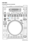
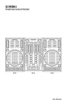
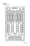
IMPORTANT SAFETY INSTRUCTIONS
1. Read Instructions – All the safety and operating
instructions should be read before this product is operated.
2. Retain Instructions
The safety and operating
instructions should be retained for future reference.
3. Heed Warnings
All warnings on the appliance and in
the operating instructions should be adhered to.
4. Follow Instructions
All operating and use instructions
should be followed.
5. Water and Moisture
The appliance should not be
used near water - for example, near a bathtub, washbowl,
kitchen sink, laundry tub, in a wet basement, or near a
swimming pool, and the like.
6. Carts and Stands
The appliance should be used only
with a cart or stand that is recommended by the
manufacturer.
An appliance and cart combination should
be moved with care. Quick stops,
excessive force, and uneven surfaces may
cause the appliance and cart combination
to overturn.
7. Wall or Ceiling Mounting
The product should be
mounted to a wall or ceiling only as recommended by the
manufacturer.
8. Heat
Appliance should be situated away from heat
sources such as radiators, heat registers, stoves, or
other appliances (including amplifiers) that produce heat.
9. Power Sources – This product should be operated only
from the type of power source indicated on the rating
label. If you are not sure of the type of power supply to
your home, consult your product dealer or local power
company. For products intended to operate from battery
power, or other sources, refer the operating instructions.
10. Grounding or Polarization – This product may be
equipped with a polarized alternation-current line plug (a
plug having one blade wider than the other). This plug
will fit into the power outlet only one way. This is a safety
feature. If you are unable to insert the plug fully into the
outlet, try reversing the plug. If the plug should still fail to
fit, contact your electrician to replace your obsolete outlet.
Do not defeat the safety purpose of the polarized plug.
11. Power-Cord Protection Power-supply cords should be
routed so that they are not likely to be walked on or
pinched by items placed upon or against them, paying
particular attention to the cord in correspondence of
plugs, convenience receptacles, and the point where
they exit from the appliance.
12. Cleaning - The appliance should be cleaned only as
recommended by the manufacturer.
Clean by wiping with a cloth slightly damp with water.
Avoid getting water inside the appliance.
13. For AC line powered units - Before returning repaired
unit to user, use an ohm-meter to measure from both AC
plug blades to all exposed metallic parts. The resistance
should be more than 100,000 ohms.
14. Non-use Periods The power cord of the appliance
should be unplugged from the outlet when left unused
for a long period of time.
15. Object and Liquid Entry Care should be taken so that
objects do not fall and liquids are not spilled into the
enclosure through openings.
16. Damage Requiring Service The appliance should be
serviced by qualified service personnel when:
A. The power-supply cord or the plug has been
damaged; or
B. Objects have fallen, or liquid has been spilled into
the appliance; or
C. The appliance has been exposed to rain; or
D. The appliance does not appear to operate normally
or exhibits a marked change in performance; or
E. The appliance has been dropped, or the enclosure
damaged.
17. Servicing The user should not attempt any service to
the appliance beyond that described in the operating
instructions. All other servicing should be referred to
qualified service personnel.
18. Ventilation – Slots and openings in the cabinet are
provided for ventilation and to ensure reliable operation
of the product and to protect it from overheating, and
these openings must not be blocked or covered. The
openings should never be blocked by placing the
product on a bed, sofa, rug, or other similar surface. This
product should not be placed in a built-in installation
such as a bookcase or rack unless proper ventilation is
the manufacturer’s instructions have been adhered to.
19. Attachments – do not use attachments not
recommended by the product manufacturer as they may
cause hazards.
20. Accessories – Do not place this product on an unstable
cart, stand, tripod, bracket, or table. The product may fall,
causing serious injury to a child or adult, and serious
damage to the product. Use only with a cart, stand,
tripod, bracket, or table recommended by the
manufacturer, or sold with the product. Any mounting of
the product should follow the manufacturer’s instructions,
and should use a mounting accessory recommended by
the manufacturer.
21. Lightning – For added protection for this product during a
lightning storm, or when it is left unattended and unused
for long periods of time, unplug it from the wall outlet and
disconnect the antenna or cable system. This will
prevent damage to the product due to lightning and
power-line surges.
22. Replacement Parts – When replacement parts are
required, be sure the service technician has used
replacement parts specified by the manufacturer or have
the same characteristics as the original part.
Unauthorized substitutions may result in fire, electric
shock, or other hazards.
23. Safety Check – Upon completion of any service or
repairs to this product, ask the service technician to
perform safety checks to determine that the product is in
proper operating condition.
FEATURES
•
•
•
•
•
•
•
Compact design
User replaceable crossfader
2 phono, 2 line, 1 microphone input
Gain, Treble, and Bass Controls on Channels
Powerful stereo headphone output
Cue Pan Selector (Ch.1-Ch.2)
Bright LED Output Indicators
MIXER FEATURES
6
4
11
10
9
3
2
1
5
7
MIC
8
MIXER FEATURES
1. Input fader - Controls individual source levels (channels) in the mix.
2. Input toggle switch - Selects which source will be active based on what you have connected to the
rear panel input section (phono/line).
3. Treble and Bass EQ - Adjusts the high and low frequency levels of the input channels for good
sound.
4. Channel Gain - Adjusts the pre-fader volume for cleaner sound.
5. Replaceable Crossfader - Achieves clean fades between the two input channels. "Hard left"
selects Channel 1. "Hard right" selects Channel 2. With the crossfader centered, both assigned
channels are live. Use the crossfader for fast and seamless (fades) from one selected
channel to the other.
Note: The crossfader is user replaceable in case of failure. Simply unscrew the two large screws
which hold it in place, lift it out and disconnect it ís cable. Re-attach the new crossfader and screw
the mounting plate back onto the unit - you're back in business!
6. Mic Input Gain - Adjusts microphone input level.
7. Mic Input - Insert your Microphone with 1/4" plug in here.
8. Headphone Input - Insert in the 1/4" plug for your headphones here.
9. Channel Cue / Cue Pan - Used to preview channel audio to your headphones. Listen here before
bringing up channel faders or moving the crossfader.
10. Headphone Level - Adjusts cue volume.
11. Master Fader - Controls the overall output level.
REAR PANEL
15 14 13 12
17 16
12. Ground - Grounding post for turntable connection. Always use this connection when using standard
turntables with ground cable. (Some turntables like the STR8-80 /100 do not require grounding wire)
13. Phono Inputs - Plug your turntables in here. W hen these connectors are used, your signal is fed
directly to the high-quality RIAA phono pre-amplifiers. Use this position only for turntables. Line
level sources will overload the sensitive phono pre-amps and will cause distortion.
14. Line Inputs - Unbalanced RCA jacks for connecting stereo audio from line level sources such as CD
players, HiFi VCRs, cassette and reel-to-reel tape decks, DAT machines, laser discs, tuners, even
synthesizers or other mixing consoles.
NOTE: Plug mono audio sources into both Left and Right inputs using a "Y" cable connector.
15. Stereo Main Outputs - Unbalanced RCA connectors controlled by the Master fader.
16. Power Connector - Plug in power adapter here and check the voltage level to match your country ís
standard.
17. Power Switch - turns unit off and on. Note*** Remember to turn ALL volume levels down when
turning on/off the unit.
QUICK SETUP DIAGRAM
Study this setup diagram. Make sure all faders are at "zero" and all devices are off. First, connect all
input sources and processors. Next, connect your microphone and monitor headphones. Finally,
connect the stereo outputs to the power amplifier(s) and/or audio receivers such as tape decks. Plug
your mixer into AC power. Now you are ready to switch everything on. IMPORTANT: Always switch on
your audio input sources such as turntables or CD players first, then your mixer, and finally any
amplifiers. When turning off, always reverse this operation by turning off amplifiers, then your mixer,
and then input devices.
TURNTABLE
TURNTABLE
POWER
SUPPLY
CD PLAYER
SOUND SYSTEM
TAPE DECK
SPECIFICATIONS
SENSITIVITY OF INPUT (LEVEL/IMPEDANCE):
LINE -14dB/47K OHM
±3dB
PHONO
-50dB /47K OHM ±3dB
MIC -54dB /6K OHM
±3dB
OUTPUT (LEVEL/IMPEDANCE):
MASTER (RCA)
0dB/47K OHM
±3dB
PHONES (LOAD=32 OHM)
-3dB/33 OHM
±3dB
MAX. OUTPUT (LOAD=47K, THD=5%)
MASTER (RCA)
MORE THAN 18dB (8V)
PHONES (LOAD=32 OHM)
MORE THAN 5dB (1.8V)
CHANNEL BALANCE
WITHIN 3dB
FREQUENCY RESPONSE:
LINE 20-20KHz
±3dB
PHONO
20-20KHz
+2 / -3dB (RIAA)
MIC 50-20KHz
+2 / -3dB
OUTPUT NOISE (IEC-A WEIGHTED)
LINE LESS THAN -75dB
PHONO
LESS THAN -65dB
MIC LESS THAN -55dB
TOTAL HARMONIC DISTORTION:
MASTER OUTPUT (LOAD=47K OHM) LESS THAN 0.2%
PHONES OUT (LOAD=32 OHM) LESS THAN 0.3%
CROSSTALK
MORE THAN 50dB AT 1KHz BETWEEN L AND R CHANNEL.
EQUALIZER:
LINE
LOW +9 / -25dB
HI
+9 / -25dB
+2 / -3dB AT 100Hz
+2 / -3dB AT 10KHz
MIC EQ
LOW +10/-10dB
HI
+10/-10dB
+2 / -3dB AT 100Hz
+2 / -3dBAT 10KHz
POWER SOURCE
AC 9V
DIMENSIONS
228 (W) X 265 (D) X 87 (H) mm
WEIGHT
2.8Kgs
Stanton Magnetics, Inc. – Warranty Provision – Returns for Repairs or Replacement
WARRANTY
Through Stanton’s authorized dealers around the World, Stanton, or one of Stanton’s authorized distributors outside the U.S.,
will, without charge, repair or replace, at the sole discretion of the entity responsible for making the repair or providing the
replacement, any Stanton merchandise proved defective in material or workmanship for a period of one (1) year following the
date of original purchase. Exceptions to this warranty are as noted below:
The warranty for mechanical parts which are subject to wear and tear are limited to the earlier to occur of thirty (30) days
following the date of original purchase or the following number of cycles: Faders - 15,000; Rotary potentiometers - 10,000; and
Switches - 10,000.
Stanton will warrant all replacement parts and repairs for ninety (90) days from the date of original shipment. Repairs made
necessary by reason of misuse, alteration, normal wear, or accident are not covered under this warranty.
RETURNS
Authorized Stanton dealers are only authorized to sell and distribute merchandise within a specific country. All goods requiring
warranty repair or replacement must be returned (freight prepaid if not hand-delivered) to the authorized Stanton dealer from
whom the merchandise was purchased and in the same country where the merchandise was purchased. For purposes of
purchases made via the Internet, the merchandise must be returned to the authorized Stanton dealer in the country where the
authorized Stanton dealer which sold the merchandise to purchaser is located and not the authorized Stanton dealer in the
country where the purchaser is located or the country in which the merchandise was received. Any returns to a non-authorized
dealer or to an authorized Stanton dealer not in the same country as the merchandise was intended to be sold or as set forth
above will void this warranty.
To initiate a warranty repair, you must contact the authorized Stanton dealer from whom you purchased the merchandise, and
follow such authorized Stanton dealer’s return policy.
Stanton assumes no risk and shall be subject to no liability for damages or loss resulting from the specific use or application
made of the merchandise. Stanton's liability for any claim, whether based on breach of contract, negligence, infringement of any
rights of any party, or product liability, and relating to the merchandise shall not exceed the price received by Stanton from your
purchase of such merchandise. In no event will Stanton be liable for any special, incidental or consequential damages (including
loss of use, loss of profit and claims of third parties) however caused, whether by the negligence of Stanton or otherwise. To the
extent permitted by law and except as otherwise provided above, Stanton disclaims any express or implied warranties of
merchantability or fitness for a particular purpose.
The above warranty provides you with specific legal rights. You may also have additional rights, which are subject to variation
from state to state and country to country.
If there is a dispute regarding the warranty of merchandise that does not fall under the warranty conditions stated above, please
include a written explanation with the merchandise when returned pursuant to the terms and conditions set forth herein.
Please register your product online at www.stantondj.com or mail your completed warranty card to:
Stanton Magnetics, Inc, 3000 SW 42 St. Hollywood, Florida 33312.
cut along dotted line
State
Where did you buy this product?
Date of Purchase
Serial Number
Model Number
PRODUCT INFO
Telephone
Country
City
Address
Name
PERSONAL INFO
Zip
If you have internet access, please register your product at
www.stantondj.com. Otherwise, return this card completely filled
out in order to validate your warranty.
STANTON WARRANTY REGISTRATION CARD
PLACE
STAMP
HERE
Stanton Magnetics, Inc.
3000 SW 42nd Street
Hollywood, FL 33312
U.S.A.