1
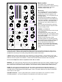
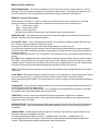
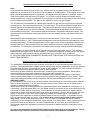
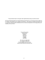
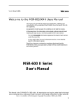
FF - 6000
DUAL FORMAT DJ MIXER
USERS MANUAL
FF - 6000 INTRODUCTION
The features and layout of the FF-6000 were determined in collaboration with leading
loudspeaker manufacturers Funktion One, who canvassed many DJs world wide on their
requirements. The result is a mixer which is not only of the highest sound quality, as you
would expect from Formula Sound, but also incorporates the features and layout which DJs
have asked for.
Although the FF-6000 is a fixed format design the use of individual circuit cards per channel, PTH
circuit boards, and all rotary controls securely mounted to the front panel, improve reliability and
aid servicing should the need arise.
A rear printed polycarbonate overlay to the top panel ensures that this mixer will still look good
after many years of use and notation will never rub off.
The FF-6000 is essentially a seven channel mixer. Six of these channels are laid out to the left of
the master section and the seventh is a dedicated microphone channel labelled ‘Console Mic’
positioned to the right of the master section
The six channels are each switchable to two input sources. Channels 1 and 2 are switchable
between low impedance microphone and a stereo line input. Phantom power is available for
microphones (internal selection).
Channels 3 to 6 are switchable between a stereo line input and a phono (RIAA) or line input.
(Phono/line selection is via a concealed push switch accessible through a hole in the rear panel).
These 6 input channels are fully assignable to the crossfader, and feature specially designed
three band equalisation with a range of +5dB to -23dB.
Gain trims are provided for all inputs accessible through the rear panel, as well as a front panel
gain control. An adjacent 5 segment led meter and clip warning indicator provide signal present
indication and overload warning. Illuminated push switches control input selection, channel routing
and cue, etc. Different shapes and sizes of push buttons along with colour coded illumination
help to easily identify control functions .
Removable Fader Panel
The fader panel mounted beneath the 6 input channels is removable and available with either
linear or rotary faders. This provides for easy removal and replacement of all faders which are
all connected by gold plated connectors. A screwdriver is the only tool required to replace a fader
or change the mixer from a linear to rotary fader operation.
Smooth feel Alps 60mm faders which are arranged to eliminate the ingress of dirt are used for
the linear fader option and superior quality rotary faders are used for the rotary option.
1
Master Section Overview
Main and Zone outputs are available in stereo, along with a separate mono output. All these
outputs are balanced on XLR connectors. Booth monitors output is available in stereo or
switchable to mono and again these outputs are balanced on XLR connectors.
A recording output is provided on gold plated phono sockets.
There are 3 insert loops provided. 1 & 2 are selected via the X-fade assign buttons and feature
latching and punch selector buttons along with wet / dry mixing control and gain trims. Mono and
cue switches are fitted to both sections. There is also an illuminated loop swap button that allows
the connected effects processors to be swapped over to the other channel.
The third effects loop is connected to the main output chain. This is selected by an illuminated
push button.
All effects loop connectors are pairs of 3 pole jacks, each socket providing send and return
paths.
Visual metering is by 2 twin 12 segment led VU meters; one for cue signals and one for output
signals.
Comprehensive headphones monitoring is provided featuring a powerful stereo headphones
amplifier.
6.5mm and 3.5mm stereo jacks are provided.
A split cue switch and monitor balance control are fitted.
The Console Microphone channel is located above the phones section and features two band
equalisation, volume control, illuminated on-off switch and cue button.
Dimensions (Exc. Knobs & connectors):
Width 483mm (19”) Height 312mm (12.25"-7RU) Depth 110mm (4.33")
Power Supply
The Mixer has a fully regulated internal power supply that is designed to operate on
220-240Vac or 110-120Vac. Selection is by an internal switch that is accessed by removing the
fader panel.
DAMAGE MAY RESULT IF THE UNIT IS CONNECTED TO THE WRONG
SUPPLY VOLTAGE.
Fuses
Mains fuse sizes are 800mA anti-surge for 220-240Vac and 1.5A anti-surge for 110-120Vac
operation.
It is important for safety reasons that the correct fuse sizes are always
used.
2
MIC
LINE
2
GAIN
CLIP
HF
INPUT CHANNELS 1 AND 2
Input Sources. These channels have balanced low impedance low
noise microphone inputs on XLR connectors and a normal stereo line
input on twin gold plated RCA phono connectors.
Input selector switch selects the input used.
Button depressed selects Mic (XLR connector)
Button not depressed selects Stereo line input.
Blue and red l.e.d.s. and labels clearly show which input is in use.
Channel meter. This is a 5 segment l.e.d. meter and it displays the
signal level within the channel. The normal reading for this meter is
amber with occasional peaks into to the red.
MID
BASS
Gain control. This sets the input gain level, and should be used in
conjunction with the rear panel gain trims. A gain trimmer is provided
for every input so that all input sources can be matched to the same
level. The control is then used to compensate for differences in track
levels.
Clip indicator. This is a red l.e.d that indicates when the channel
signal is just below clipping. If lit it means that the gain is set too high.
3 Band equalisation provides +5dB boost and -23dB cut @
HF 10kHz MID 1kHz BASS 100Hz.
The centre detent denotes the flat position.
A
X-FADE
B
CUE
X-Fade A and B. Rectangular push button switches with red and
green illumination. Depressing the switches routes the channel via
the VCA controlled crossfader and associated effects loops if
selected.
The channel signal may be routed to either end of the
X-fader.
The red and green colour coding is maintained throughout the
X-fader and associated effects loops to give clear visual indication of
routing status.
If neither button is depressed the signal is routed directly to the
output section.
Cue. A larger round illuminated push button is provided for cue
selection. When depressed the channel signal is fed to the cue buss.
Any number of sources may be selected simultaneously, the sum of
which will be available to the headphones monitoring section.
Fader. A 60mm channel fader (or rotary fader depending on what
fader option has been fitted ) is available to mix the various
channels as required.
3
PH/LINE
LINE
INPUT CHANNELS 3 to 6
3
GAIN
CLIP
HF
Input Sources. These channels have a stereo RIAA phono stage and
a normal stereo line input both on twin gold plated RCA phono
connectors. The phono stage may be configured as a second line
input by depressing a concealed push switch available through a hole
in the rear panel.
Input selector switch selects the input used.
Button depressed selects Phono/line (depending on configuration).
Button not depressed selects Stereo line input.
Blue and red l.e.d.s. and labels clearly show which input is in use.
Channel meter this is a 5 segment l.e.d. meter and it displays the prefader signal level within the channel. The normal reading for this
meter is amber with occasional peaks into the red.
MID
BASS
Gain control. This sets the input gain level, and should be used in
conjunction with the rear panel gain trims. A gain trimmer is provided
for every input so that all input sources can be matched to the same
level. The control is then used to compensate for differences in track
levels.
Clip indicator. This is a red l.e.d that indicates when the channel signal
is just below clipping. If lit it means that the gain is set too high.
3 Band equalisation provides +5dB boost and -23dB cut @
HF 10kHz MID 1kHz BASS 100Hz.
The centre detent denotes the flat position.
A
X-FADE
B
X-Fade A and B. Rectangular push button switches with red and
green illumination. Depressing the switches routes the channel via the
VCA controlled crossfader and associated effects loops if selected.
The channel signal may be routed to either end of the
X-fader.
CUE
The red and green colour coding are maintained through out the
X-fader and associated effects loops to give clear visual indication of
routing status.
If neither button is depressed the signal is routed directly to the
output section.
Cue. A larger round illuminated push button is provided for cue
selection. When depressed the channel signal is fed to the cue buss.
Any number of sources may be selected simultaneously, the sum of
which will be available to the headphones monitoring section.
Fader. A 60mm channel fader (or rotary fader depending on what
fader option has been fitted ) is available to mix the various
channels as required.
4
Master section
ZONE
LEVEL
O/P
Meter
FX 1
Trim
MONO
CUE
O/P
+8
+8
+5
+5
+3
+3
+1
+1
0
0
-1
-1
-3
-3
-5
-5
-7
-7
-10
-10
-15
-15
-20
-20
dB
dB
MONO
MASTER
HF
LEVEL
MIC ON
FX 2
VOL
Trim
CUE
MONO
Bal / Pan
R
L
BOOTH
MONITORS
CUE
LF
INSERT
IN / OUT
Bal / Pan
L
CONSOLE
MIC
R
CUE BAL
CUE
CUE
Fx Loop 1
LOOP
SWAP
Fx Loop 2
MIX
Fx Loop 1
SPLIT
Fx Loop 2
X-FADE
Latch
ON
Latch
ON
Fx Mix
Fx Mix
PHONES
Contour
OFF
Wet
Dry
Assignment
Wet
Dry
32 Ohm
To Both A & B
Punch
Punch
Direct to Masters
A
B
The master section contains all the
electronics required for the various summing
amplifiers, output stages, VU meters,
crossfade control circuits, etc.
Monitoring
The monitoring section of the FF-6000 is
very comprehensive. Visual monitoring is
provided by 2 stereo 24 segment l.e.d.
bargraph meters, 1 for cue signals and one
for output signals.
A powerful stereo headphone amplifier is
incorporated designed to drive headphones
of 32 ohms or greater. Connections are via
a 6.5mm or a 3.5mm 3 pole jack socket.
Simultaneous use of both sockets is not
possible.
The cue meter and the phones output are
both connected to the same signal so what
you see is what you hear.
CUE BAL (Cue Balance)
It is important that the function of this control
is fully understood.
The output from this control is fed to the
monitoring section (the cue bargraph meter)
and via the PHONES volume control to the
main phones output.
With the control turned fully counter
clockwise towards cue, the meter will read
the cue signal of any channel or effects loop
that has its cue button depressed, or the
sum of channels if more than one is
selected. If no cue buttons are depressed
the meter reads the main output level which
is dependent on the MASTER control
setting.
Turning the monitor balance control clockwise towards MIX feeds the programme signal (pre master) to the
monitoring section. Therefore the operator can quickly pan or mix between the PFL and mixer output. It also
facilitates the monitoring of a recording being made with the master turned down.
A SPLIT button is also provided (which is the preference of some operators). This provides a mono CUE
signal on one side of the monitor system and a mono program signal on the other side. The Mon Bal sets the
balance of the two signals in this situation. Practice and use will determine the best mode of operation.
Do not use headphones with an impedance lower than 32 ohms.
MASTER - This control sets the output level of the main balanced stereo and mono outputs, available via 3 pin
XLR connectors on the back panel. This output is monitored by the main phones and VU meter when the CUE
BAL control is set to CUE and no CUE is selected. The VU meter is factory calibrated 0dB = 0dBu (775mV)
ZONE -The zone output is almost identical to the main output in all respects except that the signal is not
available to the headphones monitoring section. The zone output level may be checked by depressing the
O/P Meter button located beneath the ZONE LEVEL control. This switch allows the o/p meter to read either
main output or zone output.
RECORD OUTPUTS - A pair of gold plated phono sockets are provided for the connection of stereo
recording equipment. The record outputs are not affected by the master level controls.
5
Master section continued
BOOTH MONITORS - This control adjusts the level of the booth monitors output which is a mix of
channels 1 to 6 only (console microphone not present in either output). The balanced outputs are via 3
pin XLR connectors. A mono signal may be obtained by using mono button located above.
INSERTS - General information
Insert sockets in the form of 3 pole 1/4” jacks are provided in pairs for the connection of external
signal processing or effects equipment. Located on the back panel the connections are:Tip = send (mixer output)
Ring = return (mixer input)
Body = common (ground)
Sockets are provided for effects loops 1 and 2 and the main output channels
INSERT IN / OUT - This switch allows the selection of external equipment inserted into the main insert
sockets. This affects the main and zone outputs.
FX LOOPS 1 and 2 - Very comprehensive facilities are provided for adding external effects into the
mix. The two loops provided have identical controls.
Routing to the effects loops follows the X-fade assign buttons on channels 1 to 6.
The effects send signals may be reduced via a rear panel trimmer located above the loop connectors.
This is to ensure that overloading of sensitive input stages is avoided and the correct level is available to
effects processors.
An effects return gain trimmer ( FX1 Trim and FX2 Trim) allows the correct level to be reintroduced into
the mix.
Dry / Wet - Once enabled this control mixes between the direct signal (effects unit input) and the effects
unit output. It is provided to mix the required amount of effect. With the control set to fully Dry no effect
is added. With the control set to fully Wet just the effect return is added to the mix and the original signal
is removed. Momentary punch and latching switches enables the Wet / Dry controls.
CUE - This button allows the operator to set up the required effect on the headphones before the effect
is selected.
LOOP SWAP - This switch allows the effects processors to be swapped e.g. if just one processor was in
use and connected to FX1 ( routed from X-FA) it could be used in loop 2 (routed from X-FB)
just by depressing LOOP SWAP. The red and green l.e.d.s also change over as a reminder that Swap is
selected.
CROSSFADE - The crossfader is a 45mm fader which can be used to smoothly fade between the XF-A
and XF-B busses and any added effects.
The crossfade system uses studio quality V.C.A.’s (voltage controlled amplifiers) to improve crossfader
life and also ensure good attenuation at the ends of travel.
CONTOUR - A contour control is provided which allows the operator to adjust the crossfader
characteristics to suit personal taste, from a gentle fade between A and B to a more aggressive fade
towards the ends of the fader.
CROSSFADE OFF - An illuminated push switch operated through a hole in the front panel is fitted below
the contour control. When depressed the crossfader is disabled. Both FX1 and FX2 loops will still be
operational.
CONSOLE MIC - A dedicated microphone channel is available. The controls are positioned to the top
right corner above the headphones section.
Two band equalisation is fitted providing +/- 12dB @ 10kHz (HF) and +/- 12dB @100Hz (LF)
An illuminated ON /OFF push switch, volume control, and illuminated CUE push switch complete the
controls. This Microphone channel is not present in the booth monitors.
6
Operational Information or how to get the best out of your mixer
Gain
In an audio mixer different signal levels from various items of equipment need to be amplified or
attenuated to a common level so that they can be added or mixed together. These signal levels may
differ considerably depending on the equipment. The signal from a microphone, for example, may be
1000 times smaller than that from a CD player. For a mixer to be as flexible as possible and to
accept signals from a variety of equipment it is necessary for the first or early stage in the input circuit
to be a variable gain amplifier. The gain of this amplifier is set by the gain control.
The FF-6000 has a combination of variable gain amplifiers to get the input signals to the required
operating level. Gain trim presets are fitted - 1 for each input. These are accessible through holes on
the back panel and are labelled accordingly. The stereo input gain trims are conventional single turn
controls. The Mic preset is a multi-turn trimmer. These trims should be adjusted to set the maximum
gain available for any input. The front panel gain control works in conjunction with these presets. The
system may be considered as coarse gain control on the rear presets and fine adjustment on the front
gain control.
When amplifier gain is introduced in a circuit noise is also introduced. (This is a fact - you cannot have
one without the other). The FF-6000 has been designed to keep this noise as low as possible by using
the latest technology. For the best performance set the gain control as low as possible to achieve the
desired output level. Gain introduced into the system and then held on the channel fader is a waste of
performance. Too much gain could result in overloading the first stage causing distortion and clipping.
A clip indicator has been included and is located below the front panel gain control. This indicator
flashes when the signal level is close to clipping. It monitors the signal at various points in the signal
chain, therefore, gain introduced by the equalisation or tone controls is also considered.
IF THE PEAK INDICATOR ILLUMINATES DURING USE TURN DOWN THE GAIN CONTROL (OR
INPUT TRIM PRESETS).
INSTALLATION, CONNECTIONS AND GOOD WIRING PRACTICE
The installation of professional audio systems should be left to experienced engineers wherever
possible. The interconnection of audio systems can be fairly complex depending on the type and size
of system and obviously well outside the scope of this handbook. We have included a few basic
points for information for anyone who is new to audio systems.
Good wiring practice should be observed when connecting any audio equipment. Good quality
connectors and screened cable should be used for all audio connections .
Twin screened cable should be used for all balanced lines particularly microphone connections.
Always ensure cable clamps in connectors are fully tightened and gripping the outer sheath. Good
strain relief and mechanically sound connections will increase reliability at virtually no extra cost.
GROUND LOOPS
In our experience this is the most common problem encountered when connecting together different
items of audio equipment. It is the most common cause of hum (50Hz noise) on a system and is
caused by incorrect system grounding.
When several items of audio equipment are connected together with unbalanced connections (i.e. 2
connections, single screened cable, etc.) the signal common connection is the screen and this will be
connected to mains earth at some point. If several items of equipment have their signal common
connected to mains earth this will form a loop (hence ground loop). Current will flow in this loop and
appear in the form of hum (50Hz mains frequency) added to the audio signal. The problem is
aggravated if the equipment is located a distance apart as the loop is larger. It is possible to have
several ground loops within a system. The solution is to connect the system to mains ground
only once. This is usually done at the mixer. You will need to investigate the various items of
equipment you are using and isolate their signal common from mains earth. Many manufacturers fit a
ground lift switch for this purpose. On some equipment this is in the form of a removable link.
Unfortunately with some equipment you have to get inside to identify where the connection is and
remove it.
You must not disconnect the mains earth wire from the mains plug of any equipment. This is
fitted for safety reasons and must be connected to ensure that the case is earthed.
7
Formula Sound reserve the right to alter specifications at any time without notice.
All Formula Sound products are designed and manufactured in our own factory which enables us
to maintain strict quality at every stage of manufacture. This attention to detail has helped to win
us 14 industry awards to date and has earned us a world wide reputation for the high quality and
reliability of our products.
Formula Sound Ltd.
Ashton Road,
Bredbury,
Stockport,
Cheshire,
England.
SK6 2SR
Tel +44 (0)161 494 5650
Fax +44(0)161 494 5651
E-mail [email protected]
Internet http://www.formula-sound.com
8
FF- 6000 Specifications
Frequency response
E.Q. set flat
20Hz - 20kHz +/-0.5dB
Maximum output level
Main output Zone output and Booth monitors output
active balanced.
+22dBu
Distortion
any input
< 0.01% typically <0.005%
Noise measured 20Hz-20kHz
Stereo inputs e.q. flat gain set to max
RIAA stage ref. 5mV 1kHz Input shorted
Microphone input (ref 150R)
EIN < -98dB
-80dBV “A” weighted
EIN < -124dBU
Gain
Stereo inputs rear trim @ max
Stereo inputs rear trim @ min
Microphone input max
Microphone input min
+/- 15dB
+ 0dB -20dB
+ 75db
+ 0dB
Maximum input level
Stereo input A (line)
Stereo input A (RIAA)
Stereo input B
Microphone
+20dBV
-8dBV 400mV
+20dBV
+4 dBV
Input Impedances
Stereo input A
Stereo input B
Microphone input
> 47k ohms
> 10k ohms
> 2k ohms active balanced
Equalisation
3 band e.q. per channel
+5dB -23 dB @
Treble 10kHz
Mid
1kHz,
Bass 100Hz
Dimensions
(Exc. Knobs & connectors):
Width 483mm (19”)
Height 312mm (12.25"-7RU)
Depth 110mm (4.33")
Balanced outputs For unbalanced operation strap pins 1&3 to ground and use pin 2 hot. This will result in no
loss of output level or performance.