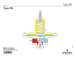
1
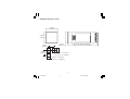
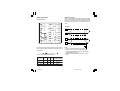
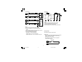
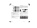
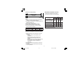
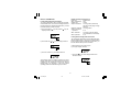
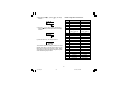
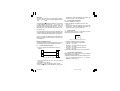
Instruction Manual
PN 31302
MODEL 7SL
HIGH/LOW LIMITROL®
1
7sl-0-00.p65
1
9/17/02, 2:35 PM
1/16 DIN, FOUR DIGIT HIGH/LOW LIMITROL
-0 0 0 - 0 - 0 0
MODEL: 0 7 S L - 9 1
Field No. 1 2 3 4 5 6 7 8 9 10 11 12 13 14 15
Fields 1 through 4. BASE
07SL - Limitrol (High/Low Limit – shipped as High Limit)
Field 6. OUTPUT (High/Low Limit)
1Relay (Form C)
Field 5. INPUT
9TC types J, K, T, E, N, S, R, B, L, U, G, D, C and
Platinel II; and Pt 100 RTD;
0 to 20 mAdc and 4 to 20 mAdc;
0 to 60 mVdc and 12 to 60 mVdc;
0 to 5 Vdc or 1 to 5 Vdc;
0 to 10 Vdc or 2 to 10 Vdc
Note: All inputs are factory calibrated and selectable
by jumper. Factory set at Type J.
Fields 7, 8. ALARMS, OPTIONS
00 None
10 One alarm – Relay Form A
11 One alarm – Relay Form A, plus
RS485 and one logic input
Note: when code 11 is specified, instrument
length is 122 mm.
Field 9. POWER SUPPLY
3100 to 240 Vac
524 Vac/Vdc
Fields 10 through 15. RESERVED
2
7sl-0-00.p65
2
9/17/02, 2:35 PM
Congratulations
Unpack the
Instrument
Congratulations on your purchase of one of the easiest to
configure high/low Limitrols on the market. After a 3 step
configuration procedure, your process will be up and
running.
Wiring
Guide to simple set-up
Configuration
To set-up the Limitrol only 3 steps are required:
1. Wire the instrument (page 7).
2. Configure the instrument (page 14).
3. Check the operating parameters (page 22).
Operating
Parameters
SV
3
7sl-0-00.p65
3
9/17/02, 2:35 PM
Table of Contents
CAUTION:
1/16 DIN, FOUR DIGIT HIGH/LOW LIMITROL .......... 2
Guide to simple set-up ...................................... 3
MOUNTING REQUIREMENTS .................................. 5
DIMENSIONS AND PANEL CUTOUT ....................... 6
WIRING GUIDELINES ............................................... 7
PRELIMINARY HARDWARE SETTINGS ............... 12
CONFIGURATION KEY FUNCTIONS ..................... 14
CONFIGURATION PROCEDURE ........................... 14
OPERATING MODE ................................................ 20
Normal Display Mode ..................................... 20
Indicators ........................................................ 20
Key Functions in Normal Display Mode .......... 21
Parameter Display Mode ................................. 21
Key Functions in Parameter Display Mode ..... 21
OPERATING PARAMETERS ................................... 22
ERROR MESSAGES ............................................... 23
DEFAULT PARAMETERS ........................................ 24
SPECIFICATIONS ................................................... 26
CALIBRATION PROCEDURE .................................. 30
General Guidelines ......................................... 30
Calibration Parameters ................................... 30
Procedure ....................................................... 31
Entering Calibration Values ............................. 31
MAINTENANCE ....................................................... 35
USE WIRE SUITABLE
FOR 75°C MINIMUM.
NOTES
• For supply connections use No 16 AWG or larger
wires rated for at least 75 °C.
• Use copper conductors only.
• Class 2 wiring must be a minimum of 1/4 inch from
any Class 1 conductors.
4
7sl-0-00.p65
4
9/17/02, 2:35 PM
MOUNTING REQUIREMENTS
Panel surface texture must be better than 6.3 µmm.
Select a mounting location with the following
characteristics:
1) Minimal vibration.
2) An ambient temperature range between 0 and
50°C (32 and 122 °F).
3) Easy access to the rear of the instrument.
4) No corrosive gases (sulfuric gas, ammonia, etc.).
5) No water or other fluid (i.e. condensation).
6) Relative humidity of 20% to 80% non condensing.
The instrument is shipped with a rubber panel gasket (50
to 60 Sh). To assure the IP65 and NEMA 4 protection,
insert the panel gasket between the instrument and the
panel as shown below.
Install the instrument as follows:
1) Insert the instrument in the gasket.
2) Insert the instrument in the panel cutout.
3) Pushing the instrument against the panel, insert the
mounting bracket.
4) Torque the mounting bracket screws between 0.3
and 0.4 Nm (2.66 and 3.54 lbf-in).
5) To insure NEMA 4X/IP65 protection, make sure the
instrument does not move within the cutout .
The instrument can be mounted on a panel up to 15 mm
(0.591 in) thick with a square cutout of 45 x 45 mm (1.772
x 1.772 in). For outline refer to Dimensions and Panel
Cutout.
Bracket
Panel
Gasket
5
7sl-1-00.p65
5
9/17/02, 2:39 PM
DIMENSIONS AND PANEL CUTOUT
48 mm
(1.890 in)
48 mm
(1.890 in)
75 mm
(2.953 in)
60 mm
(2.362 in)
10 mm
(0.394 in)
122 mm (4.803 in) w/ RS-485
105 mm (4.134 in) w/o RS-485
45 mm, -0, +0.6 mm
(1.772 in, -0, +0.024 in)
45 mm, -0, +0.6 mm
(1.772 in, -0, +0.024 in)
6
7sl-1-00.p65
6
9/17/02, 2:39 PM
WIRING GUIDELINES
A) Measuring Inputs
NOTE: Any external components (like Zener diodes,
etc.) connected between sensor and input terminals may
cause errors in measurement due to excessive and/or
not balanced line resistance or possible leakage currents.
Terminal Layout
+
11 A/A'
C
1
TC Input
C
2
10
NC
3
9
4
12 B/B'
NO
_
7
NO
OUT 1
OUT 2
PWR LINE
100/240Vac
24 Vac/dc
6
+
RS485
_
TC
10
+
LINEAR
9
13
RTD
8
C
14
DIG 1
15
_
Shield
10
5
9
+
_
Shield
NOTE:
1) Do not run input wires with power cables.
2) For TC wiring use proper compensating cable,
preferably shielded (see Thermocouple Compensating Cable Color Codes).
3) Shielded cable should be grounded at one end
only.
NOTE: When a relay output is used to drive an inductive
load, connect an external snubber network (RC) across
the terminals:
R
C
in accordance with the following table:
Load
Current
C
(µ F)
R
(Ω)
P
(W)
Resistor and
Capacitor Voltage
< 40 mA
0.047
100
1/2
260 Vac
< 150 mA
0.1
22
2
260 Vac
< 0.5 Amp
0.33
47
2
260 Vac
7
7sl-1-00.p65
7
9/17/02, 2:39 PM
RTD Input
Linear Input
10
9
+
+
_
_
RTD
RTD
mA,
mV
or
V
Shield
10
9
+
+
_
_
8
mA
mV
or
V
9
10
8
NOTE:
1) Do not run input wires with power cables.
2) High line resistance can cause measurement
errors.
3) When shielded cable is used, ground it at one end
only to avoid ground loop currents.
4) The input impedance is equal to:
Less than 5 Ω for 20 mAdc input
Greater than 1 MΩ for 60 mVdc input
Greater than 400 KΩ for 5 Vdc and 10 Vdc input
B) Logic Input
This input is used as a remote reset.
Safety note:
- Do not run logic input wiring with AC power cables.
- Use an external contact with a contact rating
greater than 0.5 mA, 5 Vdc.
- The instrument needs 100 ms to recognize a
contact status variation.
Logic input
14
15
8
8
10
NOTE:
1) Do not run RTD wires with power cables.
2) Ground shielded cable at one end only.
3) Use the correct size copper wires.
4) The resistance of the 3 wires must be the same.
G
7sl-1-00.p65
9
9/17/02, 2:39 PM
Thermocouple Compensating Cable Color Codes.
Thermocouple
Material
T Copper Constantan
J/L Iron Constantan
K Nickel Chromium
Nickel Aluminum
R Platinum/Platinum
13% Rhodium
S Platinum/Platinum
10% Rhodium
E Chromel
Constantan
B Platinum 30% Rh
Platinum 6% Rh
N Nicrosil / Nisil
British
BS 1843
+ White
- Blue
Blue
+ Yellow
- Blue
Black
+ Brown
- Blue
Red
+ White
- Blue
Green
+ White
- Blue
Green
+ Brown
- Blue
Brown
–
–
–
American
ANSI MC 96.1
+ Blue
- Red
Blue
+ White
- Red
Black
+ Yellow
- Red
Yellow
+ Black
- Red
Green
+ Black
- Red
Green
+ Violet
- Red
Violet
+ Grey
- Red
Grey
–
German
DIN 43710
+ Red
- Brown
Brown
+ Red
- Blue
Blue
+ Red
- Green
Green
+ Red
- White
White
+ Red
- White
White
–
–
–
–
–
–
9
7sl-1-00.p65
9
9/17/02, 2:39 PM
French
NFE 18-001
+ Yellow
- Blue
Blue
+ Yellow
- Black
Black
+ Yellow
- Purple
Yellow
+ White
- Green
Green
+ White
- Green
Green
–
–
–
–
–
–
C.2) Inductive Loads
C.1) Relay Outputs
OUT 1
1
Class 1
2
High voltage transients may occur when switching inductive loads. Through internal contacts these transients
may introduce disturbances which can affect the performance of the instrument. The same problem may occur
when a switch is used in series with the internal contacts
as shown below.
NO - OUT 1
C - OUT 1
NC - OUT 1
3
OUT 2
Class 1
(Alarm)
C
C
R
6
NO
7
LOAD
For all the outputs, the internal protection (varistor)
assures protection up to 0.5 Amp on inductive loads.
The cable used for relay output wiring must be as far
away as possible from input or communication cables.
Relay output: Protected by varistor.
OUT 1: Form C contact rating of 3 Amps/250 Vac
resistive load.
OUT 2: Form A Contact rating of 2 Amps/250 Vac
resistive load.
Number of operations: 2 x 10⁵ at the specified rating.
It is good electrical practice to install an additional RC network across and as close to the external contacts as
possible.
The value of capacitor (C) and resistor (R) are shown in
the following table.
NOTES:
1) To avoid shock and possible instrument damage,
connect power last.
2) For power connections use 16 AWG or larger wires
rated for 75 °C.
3) Use copper conductors only.
4) Do not run input wires with power cables.
Load
Current
C
(µ F)
R
(Ω)
P
(W)
Resistor and
Capacitor Voltage
< 40 mA
0.047
100
1/2
260 Vac
< 150 mA
0.1
22
2
260 Vac
< 0.5 Amp
0.33
47
2
260 Vac
10
7sl-1-00.p65
POWER
LINE
10
9/17/02, 2:39 PM
D) Serial Interface
The RS-485 interface can connect up to 31 instruments
with the remote master unit (see below).
For units built with optional RS-485 communication
I
N
S
T
R
U
M
E
N
T
11
12
A/A'
B/B'
I
N
S
T
R
U
M
E
N
T
A'/A
M
A
S
T
E
R
B'/B
COMMON
13
I
N
S
T
R
U
M
E
N
T
Maximum cable length: 1.5 km (9/10 mile) at 9600 baud.
NOTE: According to EIA specification for RS-485:
a) The “A” terminal of the generator shall be negative
with respect to the “B” terminal for a binary 1
(MARK or OFF) state.
b) The “A” terminal of the generator shall be positive
with respect to the “B” terminal for a binary 0
(SPACE or ON) state.
11
12
A'/A
A/A'
B'/B
B/B'
COMMON
13
11
12
13
11
7sl-1-00.p65
11
9/17/02, 2:39 PM
M
A
S
T
E
R
E) Power Line and grounding
4
5
PRELIMINARY HARDWARE SETTINGS
N, L2
1) Remove the instrument from its case.
2) Set J106 according to the following table:
POWER SUPPLY
100 to 240 Vac
24 Vac/Vdc
N, L2
R (S,T), L1
R (S,T), L1
Input Type
Power Supply
Type
Current
Voltage
24 Vac/Vdc
T
500 mA
250 V
100/240 Vac
T
125 mA
250 V
0-10V, 2-10 V
open open close open
open open open close
0-20 mA, 4-20 mA
Input CTTC R192=180K
SH120=Closed CH101=Open
When the fuse is damaged the instrument should be
returned to your supplier to check the power supply.
7) Safety requirements for permanently connected
equipment:
- Include a switch or circuit-breaker in the
installation.
- Place the switch in close proximity to the
equipment and within easy reach of the
operator.
- Mark the switch as the disconnecting device for
the equipment. NOTE: A single switch or
circuit-breaker can drive more than one
instrument.
8) When the NEUTRAL line is present, connect it to
terminal 4.
9) To avoid shock and possible instrument damage,
connect power last.
12
7sl-1-00.p65
12
J106
3-4 5-6
7-8
T/C, RTD,
0-60 mV, 12-60 mV
close open open open
(standard configuration)
open close open open
0-5 V, 1-5V
NOTE:
1) Before connecting the power line, check that the
voltage is correct (see Model Number).
2) For supply connections use 16 AWG or larger wires
rated for at least 75 °C.
3) Use copper conductors only.
4) Do not run input wires with power cables.
5) Polarity does not matter for 24 Vdc wiring.
6) The power supply input is not fuse protected.
Please provide it externally.
1-2
9/17/02, 2:39 PM
Limitrol with RS-485
2
4
6
8
1
3
5
7
J106
V101
Limitrol without RS-485
13
7sl-1-00.p65
13
9/17/02, 2:39 PM
CONFIGURATION KEY FUNCTIONS
RESET In Configuration Mode, used only to scroll
back parameters
The following is a complete list of parameters. The lower
display will show the parameter code (L1 to d1) and the
upper display will show the selection code or numerical
value. No timeout is applied in the configuration mode.
Used in Configuration Mode to decrease the
parameter value.
L1 = Serial Interface Protocol
(Skipped if option is not available.)
OFF = No serial interface
nbUS= Modbus
jbUS = Jbus
Used in Configuration Mode to increase the
parameter value.
FUNC
Monitors/Modifies parameters.
+
Loads the default parameters.
L2 = Serial Link Device Address
(Skipped if option is not available or L1 = OFF)
From 1 to 255
NOTE: The device can connect up to 31 instruments.
+ FUNC or + FUNC
Increases/decreases values at a higher rate
when modifying parameters.
L3 = Baud Rate for Serial Link
(Skipped if option is not available or L1 = OFF)
Set value from 600 to 19200 baud.
(19200 baud is shown on display as 1920)
+ RESET or + RESET
Jumps to the Maximum or Minimum parameter
value when modifying parameters.
L4 = Byte Format for Serial Link
(Skipped if option is not available or L1 = OFF)
8E = 8 bits + even parity
8O = 8 bits + odd parity
8
= 8 bits without parity
CONFIGURATION PROCEDURE
1) Remove the instrument from its case.
2) Open switch V101 (See illustrations under “Preliminary Hardware Settings.”)
3) Re-insert the instrument in its case.
4) Switch on power to the instrument.
The upper display will show COnF.
5) Press the “ ” key and the lower display will show the
firmware version.
Press the "FUNC" key to start the configuration procedure with the first parameter (L1). Press the "RESET"
key to start the configuration procedure with the last
parameter (d1).
14
7sl-2-00.p65
14
9/17/02, 2:40 PM
r1 =
0 =
1 =
2 =
3 =
4 =
5 =
6 =
7 =
8 =
9 =
10 =
11 =
12 =
13 =
14 =
15 =
16 =
17 =
18 =
19 =
20 =
21 =
22 =
23 =
24 =
25 =
26 =
27 =
28 =
29 =
30 =
31 =
32 =
33 =
34 =
35 =
36 =
37 =
Input Type and Range Value
TC J
From -100
to
TC K
From -100
to
TC T
From -200
to
TC E
From -100
to
TC N
From -100
to
TC S
From
-50
to
TC R
From
-50
to
TC B
From
0
to
TC L
From -100
to
TC U
From -200
to
TC G
From
0
to
TC D
From
0
to
TC C
From
0
to
TC Plat. II
From -100
to
RTD Pt 100 From -200
to
Linear
From
0
to
Linear
From
12
to
Linear
From
0
to
Linear
From
4
to
Linear
From
0
to
Linear
From
1
to
Linear
From
0
to
Linear
From
2
to
TC J
From -150
to
TC K
From -150
to
TC T
From -330
to
TC E
From -150
to
TC N
From -150
to
TC S
From
-60
to
TC R
From
-60
to
TC B
From
32
to
TC L
From -150
to
TC U
From -330
to
TC G
From
0
to
TC D
From
0
to
TC C
From
0
to
TC Plat. II
From -150
to
RTD Pt100 From -330
to
1000
1370
400
800
1400
1760
1760
1820
900
600
2300
2300
2300
1400
850
60
60
20
20
5
5
10
10
1830
2500
750
1470
2550
3200
3200
3300
1650
1110
4170
4170
4170
2550
1560
r2 = Decimal Point Position
(Available only for linear range r1 = 15 to 22)
____.
= No decimal
___._
= One decimal place
__.__
= Two decimal places
_.___
= Three decimal places
°C
°C
°C
°C
°C
°C
°C
°C
°C
°C
°C
°C
°C
°C
°C
mV
mV
mA
mA
V
V
V
V
°F
°F
°F
°F
°F
°F
°F
°F
°F
°F
°F
°F
°F
°F
°F
r3 = Low Scale Range Value
(Available only for linear range r1 = 15 to 22)
Range: From -1999 to 9999
r4 = High Scale Range Value
(Available only for linear range r1 = 15 to 22)
Range: From -1999 to 9999
r5 = Offset Adjustment
Range: From -500 to 500
Offset value algebraically added to the measured value.
r6 = Time Constant for Filter on Displayed Value
Range: From 0 (filter OFF) to 8 seconds.
(First order filter with selected time constant.)
r7 = Alarm Action on Fault
uP = The alarm assumes an upscale reading.
doun = The alarm assumes a downscale reading.
C1 = Type of Limit Action
Hi. = High limit (for heating process)
Lo. = Low limit (for cooling process)
Hi.Lo = Band limit (for special process)
C2 = Acknowledgment Mode
O = The acknowledgment action is ignored if performed
when setpoint is exceeded.
I = The acknowledgment action is recognized also
when the setpoint is exceeded. (In this case, the
control output is instantaneously restored when
process variable is within setpoint).
15
7sl-2-00.p65
15
9/17/02, 2:40 PM
Example of limit function when C1 = Hi and C2 = O
Control Output Function
The relay output operates in fail-safe mode (relay deenergized during reset condition) and latching mode.
HS
(Setpoint
threshold
hysteresis)
ON
Relay OUT 1
OFF
The control output turns OFF when the setpoint is exceeded when C1 = Hi, or C1 = Lo. (When C1 = Hi.Lo
control output turns off when the process is greater than
“Su” or less than “S1”).
Su
(Setpoint
threshold)
ON
"Reset" LED
OFF
The control output remains OFF until the process is
within setpoint and the acknowledge action has been
performed (the sequence of action may or may not be
important depending on parameter C2).
Flash
Upper display
Steady
FLASH
FLASH
A
The upper display flashes when the setpoint is exceeded
and returns to a steady display when the process is within
setpoint.
B
C
A, B, C = Acknowledgment action by RESET button,
digital input or serial link. NOTE: Acknowledgment B has
no effect.
When the control output is OFF the RESET LED is ON
(if C2 = 0) or flashes (if C2 = 1).
Example of limit function when C1 = Hi and C2 = 1
When C2 = 1 the RESET LED is steady ON when control
output is OFF and acknowledged.
Su
(Setpoint
threshold)
(Hysteresis)
The reset condition can be stored in permanent memory
(see C4).
ON
Relay OUT 1
OFF
Acknowledgment can be performed by pressing the
RESET key, by momentarily closing the external dry
contact or by a command from the serial link.
The length of the reset condition and max/min values
detected are stored in memory and available for viewing
until the next reset condition occurs. The information is
lost at power down.
ON
"Reset" LED
OFF
FLASH
FLASH
Flash
Upper display
Steady
FLASH
FLASH
A
During a reset condition the values are continuously
updated and can be monitored.
A, B = Acknowledgment action by RESET button, digital
input or serial link.
16
7sl-2-00.p65
16
B
9/17/02, 2:40 PM
C3 = Reset at Power-up
Auto = Automatic reset
P2 = H.A.
nAn = Manual reset
C4
0
1
= Reset Memory
= The reset condition will be saved (at next
power up it will be reactivated)
= The reset condition will be lost in case of
power down
P2 = L.A.
P2 = H.A.Ac
C5 = Time Constant for Filter on Measured Value
for Reset Action
Range: From 0 (filter OFF) to 8 seconds
Note: First order filter with selected time Constant.
P1 = Alarm Function
(Skipped if option not available)
nonE = Not provided
AL.P = Process alarm
AL.b = Band alarm
AL.d = Deviation alarm
When C1 = Hi.Lo, “AL.b” and “AL.d” are not available.
Alarm
still
exists
Ack.
LED lit steady
Relay in alarm status
No
Ack.
LED flashing
Relay in alarm status
Alarm
clears
LED off
Relay not in alarm status
Alarm
still
exists
Ack.
LED lit steady
Relay not in alarm status
No
Ack.
LED flashing
Relay in alarm status
P2 = L.A.Ac
Alarm
clears
LED off
Relay not in alarm status
Ack.
LED lit steady
Relay in alarm status
P2 = H.L.
Alarm
still
exists
No
Ack.
LED flashing
Relay in alarm status
Alarm
clears
Ack.
P2 = L.L.
LED OFF
Relay not in alarm status
No
Ack.
LED flashing
Relay in alarm status
Ack. = Alarm Acknowledgment
(For relay status see configuration parameter P3.)
P2 = Alarm configuration
(Skipped if option is not available or P1 = none)
H.A. = High alarm with automatic reset
L.A. = Low alarm with automatic reset
H.A.Ac = High alarm with automatic reset and
acknowledge
L.A.Ac =Low alarm with automatic reset and
acknowledge
H.L. = High alarm with manual reset
L.L. = Low alarm with manual reset
Example for P2 = H.A.
(Alarm
threshold)
(Hysteresis)
Alarm status*
Relay
No alarm status
ON
ALM LED
OFF
NOTE: For band alarm, H.A./H.A.Ac/H.L. signifies
outside band alarm, while L.A./ L.A.Ac/L.L. signifies
inside band alarm.
FLASH
ACK
ACK = Alarm acknowledgment from "AK" parameter
or serial link.
For every alarm configuration:
LED flashes, relay placed in alarm status
* Alarm Status:Relay energized (P3 = dir)
Relay de-energized (P3 =rEV)
17
7sl-2-00.p65
17
FLASH
9/17/02, 2:40 PM
Example for P2 = H.A.A.c
P3 = Alarm Action
(Skipped if option not is available or P1 = none)
dir =
Direct action
(Relay energized in alarm condition)
rEV =
Reverse action
(Relay energized in non-alarm condition)
(Alarm
threshold)
(Hysteresis)
Alarm status*
Relay
No alarm status
ON
ALM LED
OFF
FLASH
P4 =
Alarm Standby Function
(Skipped if option is not available or P1= none)
OFF =
Standby function disabled
On =
Standby function enabled
FLASH
ACK
ACK = Alarm acknowledgment from "AK" parameter
or serial link.
If the alarm is programmed as band or deviation, this
function masks the alarm condition at start up and at a
“Su” setpoint change until the process variable reaches
the alarm threshold, plus or minus hysteresis. This standby
function masks a Process Alarm condition at start up until
the process variable reaches the alarm threshold plus or
minus hysteresis.
* Alarm Status:Relay energized (P3 = dir)
Relay de-energized (P3 =rEV)
Example for P2 = H.L.
PF = Time Constant for Filter on Measured Value for
Alarm Action
(Skipped if option is not available or P1 = none)
Range: From 0 (filter OFF) to 8 seconds
(First order filter with selected time constant.)
(Alarm
threshold)
(Hysteresis)
Alarm status*
Relay
No alarm status
ON
ALM LED
OFF
FLASH
n 1 = Safety Lock
0
=
UNLOCKed. The device is always UNLOCKed
and all parameters can be modified.
l
=
LOCKed. The device is always LOCKed and
no parameters can be modified
From 2 to 9999 = This number is a password, to be used
in run time (see “nn”), to LOCK/UNLOCK the
device.
FLASH
ACK
ACK
ACK = Alarm acknowledgment from "AK" parameter
or serial link.
* Alarm Status:Relay energized (P3 = dir)
Relay de-energized (P3 =rEV)
18
7sl-2-00.p65
18
9/17/02, 2:40 PM
t1 = Timeout Selection
tn10 =
10 second timeout
tn30 =
30 second timeout
d1 = Digital Input (contact closure)
(This is a read only parameter)
Enb =
Digital input enabled
dlS =
Digital input disabled
(The digital input is used as a remote process restart.)
The configuration procedure is now complete.
display should show "COnF".
The
19
7sl-2-00.p65
19
9/17/02, 2:40 PM
6) The upper display shows the minimum value of the
process variable detected during the last "reset" condition while the lower display shows "PL.” (if no data
is available, the upper display will show “- - - -”) This
information is not available if C1 = Hi. The information
is lost at power down and at powerup the device will
display the process variable .
OPERATING MODE
1) Remove the instrument from its case.
2) Set switch V101 to the closed position.
3) Re-insert the instrument in its case.
4) Switch on the instrument.
Normal Display Mode
On powerup the device starts in the "Normal Display
Mode."
NOTE: in case the “reset condition” was generated by
a fault condition in the measure variable, the upper
By pressing the
or key, it is possible to change the
displayed information; therefore, one of the following
display modes can be selected:
display will indicate "m.Err"
At powerup the display will show the process variable
unless otherwise stated in one of the above display
options
1) The upper display shows the measured value while
the lower display shows the "Pu" (Process variable)
2) The upper display shows the setpoint threshold while
the lower display shows "Su." If this display was active
at power down, it will be active at powerup.
3) The upper display shows the setpoint1 threshold
while the lower display shows "S1." This information
is available only if C1 = Hi.Lo If this display was active
at power down, it will be active at powerup
4) The upper display shows the total time (hh.mm) of the
last reset condition while the lower displays shows “t.”
(if no data is available, the upper display will show
"- - - -" ). The information is lost at power down and at
powerup the device will display the process variable.
5) The upper display shows the maximum value of
process variable detected during the last "reset" condition while the lower display shows "Ph." (if no data
is available, the upper display will show “- - - -” ). This
information is not available if C1 = Lo. The information
is lost at power down and at powerup the device will
display the process variable.
If, at power off, the device was in reset condition and
configured to save it (C4 = 0), and/or it was programmed
for manual reset at startup (C3 = 1), then at the next
power up the lower display will be flashing.
Indicators
“RESET“ =
“ALM”
NOTE: In case the reset condition was generated by a
fault condition in the measure variable, the upper display
will indicate "m.Err"
=
Indicates control output status
as follows:
a) With configuration parameter
C2 = 0
LED ON when Output is OFF
LED OFF when Output is ON
b) With configuration parameter
C2 = 1
LED flashes when Output is OFF
LED ON when Output is OFF
and acknowledged
LED OFF when Output is ON
Indicates alarm status as follows:
Flashes when alarm is ON
ON when alarm has been
acknowledged
OFF when alarm is OFF
20
7sl-3-00.p65
20
9/17/02, 2:41 PM
All parameters (except
device is UNLOCKed.
Key Functions in Normal Display Mode
“FUNC” = By pressing it, the display changes from
“Normal Display Mode” to “Parameter
Display Mode.”
=
) can be modified only when the
The LOCK/UNLOCK status can be selected in configuration using parameter n1 or during the operating mode
with the parameter password.
Pressing it for more than ten seconds
initiates the Lamp Test. During the
Lamp Test the device functions normally
while all display segments and LED's
are lit with a 50% duty cycle. No timeout
is applied to a lamp test.
To switch from LOCKED to UNLOCKED, enter the n1
parameter setting. To switch from UNLOCKED to
LOCKED, enter any number other than the n1 parameter
setting.
Press the "FUNC" key again to end the
Lamp Test.
When the device is in remote (the serial link controls the
device) no parameters can be modified.
" " or “ " =
By pressing these keys it is possible to
change the displayed information. See
“Normal Display Mode” on previous page.
“RESET” =
Press and hold for 1 second to initiate
“reset.”
Key Functions in Parameter Display Mode
FUNC
= Press the “FUNC” key again and the
instrument stores the new setting
(if changed) and goes to the next
parameter.
Parameter Display Mode
The "FUNC" key initiates the Parameter Display Mode
when pressed for less than 10 seconds in the "Normal
Display Mode."
or
=
Changes the setting of the selected
parameter.
RESET
=
Press and hold for more than 1 second to
initiate reset.
The lower display shows the parameter identification
code while the upper display shows the parameter value.
The value of these parameters can be modified with the
and keys.
Press the "FUNC" key again to store the new value and
advance to the next parameter.
If no keys are pressed within the timeout period (see t1),
the display will automatically return to the "Normal Display Mode" in the previous display and any modifications
of the last displayed parameter will be lost.
21
7sl-3-00.p65
21
9/17/02, 2:41 PM
OPERATING PARAMETERS
Alarm Threshold (optional)
(Available only if P1=AL.P, AL.b or AL.d.)
Lower display: AL
Upper display: Alarm threshold value
Range:
Span limits
(if process alarm
P1 = AL.P)
From 0 to 500
(if band alarm
P1 = AL.b)
From -500 to 500 (if deviation alarm P1 = AL.d)
Some of the following parameters may not appear,
depending on the configuration.
Alarm Acknowledge
(Available only if P1 = AL.p, AL.b or AL.d)
Lower display:
Upper display: OFF/ON
Select ON and press the FUNC key
in order to acknowledge the alarm.
ON = Alarm Acknowledged
OFF = Alarm Not Acknowledged
Alarm Hysteresis (optional)
(Available only if P1 = AL.P, AL.b or AL.d)
Lower display: HA
Upper display: Hysteresis value
Range:
From 0.1% to 10.0% of span value
or 1 LSD
Software Key
(Skipped if n1 = 0 or 1)
Lower display: nn
Upper display: Numeric password to
LOCK/UNLOCK the device
NOTE: The upper display will
initially show the "LOCK" status.
ON = the device is LOCKED.
OFF = the device is UNLOCKED.
Serial LInk (optional)
The device can be connected to a host computer via
serial link.
The host can put the device in LOCAL (parameters are
controlled via keyboard) or in REMOTE (functions and
parameters are controlled via serial link).
Setpoint Threshold
Lower display: Su
Upper display: Setpoint threshold value
Range:
Span limits (From "S1" to high span
limit when C1 = Hi.Lo)
REMOTE is signified by the decimal point to the left of
"RMT" which is on the right side of the numeric display.
Via serial link it is possible to read and/or to modify all the
operative and configuration parameters.
The following conditions must apply to implement this
function:
1) Configure parameters L1 through L4 with the front
keyboard
2) The device must be in the Operating mode.
Setpoint1 Threshold
(Available when C1 = Hi.Lo)
Lower display: S1
Upper display: Setpoint threshold value
Range:
From low span limit to "Su"
Control output is OFF during the download procedure.
Setpoint Threshold Hysteresis
Lower display: HS
Upper display: Hysteresis value
Range:
From 0.1% to 10.0% of span value
or 1 LSD
At the end of configuration downloading procedure the
device preforms an automatic reset and returns to normal
condition.
22
7sl-3-00.p65
22
9/17/02, 2:41 PM
Error List
100
150
200
XXX
301
307
400
500
502
510
ERROR MESSAGES
Overrange, Underrange and
Sensor Break Indications
This device detects process variable faults
(OVERRANGE, UNDERRANGE OR SENSOR BREAK).
When the process variable exceeds the span limits
established by configuration parameter r1 an
OVERRANGE condition will appear as:
Error in EEPROM writing
Short circuit on CPU's outputs
Error on "protect register" in EEPROM
Configuration parameter error.
Error on calibration of selected input.
rj input calibration error.
Error on operative parameter.
Error on autozero measurement.
Error on reference junction measurement.
Error during calibration procedure.
Dealing with Error Messages
1) When a configuration parameter error is detected,
repeat the configuration procedure of that specific
parameter.
2) If an error 400 is detected, simultaneously press
the
and keys to load the default parameters
and then repeat the control parameter setup.
3) For all other errors, contact your
Service Representative.
An UNDERRANGE condition will appear as:
A sensor break is signaled as "OPEN”. On the mA/V
input, a sensor break can be detected only when the
range selected has a zero elevation (4/20 mA, 12/60 mV,
1/5 V or 2/10 V.)
On the RTD input "shrt" is signalled when input resistance is less than 15 Ω (short circuit sensor detection).
This device detects reference junction errors or errors on
the internal autozero measurement. When a fault is
detected the output goes OFF and the alarm assumes an
upscale/downscale reading in accordance with r7.
Error Messages
On powerup, the instrument performs a self-diagnostic
test. When an error is detected, the lower display shows
an "Er" indication while the upper display shows the code
of the detected error.
23
7sl-4-00.p65
23
9/17/02, 2:42 PM
Default Operating Parameters List
Parameter
Default Value
Alarm Acknowledge OFF
Software Key
Unlock
Setpoint Threshold
Low range value (if low limit)
High range value (if high or high/
low limit)
Setpoint1 Threshold Low range value
Setpoint Threshold
Hysteresis
0.1%
Alarm Threshold
Low range (if process alarm)
100 (if deviation or band alarm)
Alarm Hysteresis
0.1%
DEFAULT PARAMETERS
Loading Default Operating Parameters
The control parameters can be loaded with predetermined default values. These are the settings loaded into
the instrument prior to shipment from the factory. To load
the default values proceed as follows:
a) Press and hold the
displays will show:
b) Press either the
or
key and press the
key; the
Loading Default Configuration Parameters
The configuration parameters can be loaded with predetermined default values. These are the settings loaded
into the instrument prior to shipment from the factory. To
load the default values proceed as follows:
key; the display will show:
a) Internal switch V101 must be open.
b) The upper display will show:
c) Press the "FUNC" key; the display will show:
c) Press the key; the lower display will show the
firmware version.
This indicates that the loading procedure has been
initiated. After about 3 seconds the loading procedure is
complete and the instrument reverts to the “Normal
Display Mode.” The following is a list of the default
operating parameters loaded during the procedure:
24
7sl-4-00.p65
24
9/17/02, 2:42 PM
d) Still holding the
will show:
key, press the
key; the display
Default Configuration Parameter List
PARA.
L1
L2
L3
L4
r1
e) Press the
key to select Table 1 (European) or
Table 2 (American) default parameters; the display
will show:
r2
r3
r4
r5
r6
r7
c1
c2
c3
c4
c5
P1
P2
P3
P4
PF
n1
t1
f) Press the FUNC key; the display will show:
This indicates that the loading procedure has been
initiated. After about 3 seconds the procedure is complete and the instrument reverts to the “COnF” display.
The following is a list of the default configuration parameters loaded during the procedure:
Table 1
European
nbUS
1
19200
8E
Type J
(-100 to 1000 °C)
——.
-100
1000
0
1 second
uP
Hi
1
Auto
0
1 second
nonE
H.A.
rEV
OFF
1 second
0
10 seconds
Table 2
American
nbus
1
19200
8E
Type J
(-150 to 1830 °F)
——.
-150
1830
0
1 second
uP
Hi
0
Auto
0
1 second
nonE
H.A.Ac
rEV
OFF
1 second
0
30 seconds
25
7sl-4-00.p65
25
9/17/02, 2:42 PM
SPECIFICATIONS
“ALM” indicates alarm status as follows:
Flashes when alarm is ON.
ON when alarm has been
acknowledged
OFF when alarm is OFF
RMT
A decimal point on the right side
of the upper display flashes to
indicate the device is controlled
by serial link
Keyboard
Four keys (covered by polyester membrane) labelled RESET, , & FUNC.
Power Supply 100 to 240 Vac 50/60 Hz switching or
24 Vac/Vdc with interruptions less than
100 ms
Power Supply Variation
-15% to 10% (for 100 to 240 Vac)
-10% to 10% (for 24 Vac/Vdc)
Power Consumption 8 VA max
Insulation Resistance Greater than 100 MΩ
Insulation Strength1500 V rms for 1 minute
EC Compatibility
Conforms with 89/336/EEC directives regarding electro-magnetic compatibility
Emission Complies with:
Generic emission standard EN50081-2
Immunity Complies with the generic immunity standard EN50082-2. Conforms
with 72/23/EEC and 93/68/EEC directives
regarding low voltage. It complies with the
safety requirements for electrical equipment for measurement, control and
laboratory use, Generic Standard
EN61010-1, Installation Category II.
Sampling
Time
250 ms for linear input
500 ms for TC/RTD input
Case
RABS Grey dark color (RAL 7043).
Self-extinguishing degree V0
according to UL 94
Front panel Designed and tested for IP65 and NEMA
4X for indoor location (when panel gasket
is installed). Tests were performed in
accordance with IEC 529, CEI 70-1 and
NEMA 250-1991 STD.
Installation Panel mounting
Rear Terminal Block
15 screw terminals with safety rear cover
Dimensions Unit with RS-485 communications
DIN 43700 48 x 48 mm x 122 mm
(1.890 x 1.890 in. x 4.803 in).
Dimensions Unit without RS-485 communications
DIN 43700 48 x 48 mm x 105 mm
(1.890 x 1.890 in. x 4.134 in).
Cutout
45 x 45 mm (1.772 x 1.772 in).
Weight
250 g (8.75 oz).
Upper Display 4 digits, 7 segment red LED’s with
decimal point, 7.62 mm high (0.3 in).
Lower Display 2 digits, 7 segment red LED’s with
decimal point, 7.62 mm high (0.3 in).
Indicator
2 red LED annunciators for:
“RESET” Indicates control output status
as follows:
a)
With configuration parameter
C2 = 0
LED ON when Output is OFF
LED OFF when Output is ON
b)
With configuration parameter
C2 = 1
LED flashes when Output is OFF
LED ON when Output is OFF
and acknowledged
LED OFF when Output is ON
26
7sl-5-00.p65
26
9/17/02, 2:43 PM
Range
Display Update Time
500 ms
The display value can be filtered
Reference Accuracy
± 0.2% fsv ±1 digit @ 25 °C and nominal
power supply voltage.
Temperature Drift
Less than 200 ppm/°C of full span for mV
and TC ranges 1, 2, 4, 5, 9, 14 (CJ
excluded).
Less than 300 ppm/°C of full span for mA/
V and TC ranges 11, 12, 13 (CJ excluded)
Less than 400 ppm/°C of full span for RTD
range 15 and TC range 10 (CJ excluded).
Less than 500 ppm/°C of full span for TC
ranges 3, 6, 7 (CJ excluded).
Less than 600 ppm/°C of full span for TC
range 8.
NOTE: Precision and drift guaranteed
(for T>300°C/570°F).
Reference Junction Drift
0.1 °C/°C
Common Mode Rejection Ratio
120 dB @ 50/60 Hz
Normal Mode Rejection Ratio
60 dB @ 50/60 Hz
Ambient Temperature
0 to 50 °C
Storage Temperature
-20 to 70 °C
Humidity
Maximum of 85% RH non condensing
Input
Thermocouple (J, K, T, E, N, S, R, B, L, U,
G, D, C, Platinel II), RTD Pt100, mVdc,
Vdc, mAdc. The type of inputs are keyboard and jumper selectable.
1) TC type J
-100 to 1000 °C
-150 to 1830 °F
2) TC type K,
-100 to 1370 °C
-150 to 2500 °F
3) TC type T
-200 to 400 °C
-330 to 750 °F
4) TC type E
-100 to 800 °C
-150 to 1470 °F
5) TC type N
-100 to 1400 °C
-150 to 2550 °F
6) TC type S
-50 to 1760 °C
-60 to 3200 °F
7) TC type R
-50 to 1760 °C
-60 to 3200 °F
8) TC type B
0 to 1820 °C
32 to 3300 °F
9) TC type L [DIN43710-1977]
-100 to 900 °C
-150 to 1650 °F
10) TC type U [DIN43710-1977]
-200 to 600 °C
-330 to 1110 °F
11) TC type G [W - W, 26% Re]
0 to 2300 °C
0 to 4170 °F
12) TC type D [W, 3% Re - W, 25% Re]
0 to 2300 °C
0 to 4170 °F
13) TC type C
0 to 2300 °C
0 to 4170 °F
14) TC type Platinel II
-100 to 1400 °C
-150 to 2550 °F
15) RTD PT100
-200 to 850 °C
-330 to 1560 °F
16) Linear
0 to
20 mA
17) Linear
0 to
60 mV
18) Linear
0 to
5 V
19) Linear
0 to
10 V
27
7sl-5-00.p65
27
9/17/02, 2:43 PM
Source Impedance
100 Ω maximum for TC/mV input
Less than 20 Ω per wire for RTD input
Input Impedance
Greater than 1 MΩ for TC/mV input
Greater than 400 KΩ for 5V to 10V input
range
Less than 5 Ω for mA input
Cold Junction
Automatic compensation from 0 to 50 °C
Digital Input Input from dry contact (voltage free) to
restart process (optional)
Control OUT 1
Relay (form C) 3 Amp @ 250 Vac resistive
load (with varistor on contacts)
(Relay operates in failsafe mode)
Limit Type High limit (for heating process)
Low limit (for cooling process)
High/Low limit (for special process)
Acknowledgment Mode
To restart the process, two conditions
must apply
a) The process returns within setpoint
b) The operator has acknowledged the
process (from keyboard, digital input or
serial link)
The “a” and “b” sequence may or may not
matter depending on C2 (see C2)
Power-Up Mode
Automatic or Manual restart. When in
automatic restart the control output is guaranteed OFF for 1 second.
Setpoint Threshold
Span limits
Threshold hysteresis
From 0.1 to 10.0% of span value or 1 LSD
(whichever is greater)
OUT 2
Relay (form A) 2 Amp @ 250 Vac resistive
load. OUT 2 is used as alarm output
(optional)
Alarm Function
Process alarm
Deviation alarm
Band alarm
Type of Alarm
High/Low (Outside/Inside if band alarm)
Direct/Reverse
Automatic/Manual reset
Standby sequence/No standby sequence
Alarm Threshold
Span limits for process alarm
From 0 to 500 digits for band alarm
From -500 to 500 digits for deviation alarm
Alarm Hysteresis
From 0.1 to 10.0% of span value or 1 LSD
(whichever is greater)
Serial Interface
RS-485 Opto-isolated (optional)
Protocol Type
Modbus/Jbus (RTU mode)
Device Address
From 1 to 255. NOTE: The interface can
support up to 31 devices
Baud Rate 600 up to 19200 baud
Format
1 start bit
8 bit with/without parity
1 stop bit
Parity
Even/Odd
Watch dog Hw/Sw is provided for automatic restart
Protection Internal dip switch for calibration and configuration parameter protection.
28
7sl-5-00.p65
28
9/17/02, 2:43 PM
References
UL 94
ENV50141
Electromagnetic compatibility - Basic immunity standard - Conducted disturbances
induced by radio-frequency fields - Immunity test.
DIN 43710-1977
Thermocouples - Reference table.
IEC 584-1
Thermocouples - Part 1 - Reference table.
DIN 43760
Thermometer Reference table.
Tests for flammability of plastic materials
for pans in devices and appliances
CEI 70-1 (IEC 529)
Degrees of protection provided by enclosures (IP Code)
NEMA 250-1991
Enclosures for equipment (1000 Volts
maximum)
DIN 43700
Measurements and control instruments
for panel mounting. Nominal front and
cut-out dimensions.
EN 50081-2 Electromagnetic compatibility - Generic
emission standard - Part 2. Industrial
environment.
EN 55011
Limits and methods of measurement of
radio disturbance characteristics of industrial, scientific and medical (ISM) radio
frequency equipment.
EN 50082-2 Electromagnetic compatibility - Part 2 Industrial environment
ENV50140
Electromagnetic compatibility - Basic immunity standard Radiated radio - frequency electro-magnetic field- Immunity test.
IEC 1000-4-2 Electromagnetic compatibility (EMC)
Part 4: Testing and measurement technique. Section 2: Electrostatic discharge
immunity test.
EN-61000-4-8 Electromagnetic compatibility (EMC)
Part 4: Testing and measurement techniques
Section 8: Power frequency magnetic field
immunity test.
IEC 1000-4-4 Electromagnetic compatibility. Part 4:
Testing and measurement techniques Section 4: Electrical fast transient/burst
immunity test.
29
7sl-5-00.p65
29
9/17/02, 2:43 PM
f) during calibration, connect one input at a time to the
rear terminal block.
g) Use calibrators with the following:
Accuracy
TC Input:
+0.005% output
+0.001% range
+5 mV
RTD Input:
+0.02%
+0.0025 Ω decade
CJ Compensation:
better than 0.1°C
Current Transformer: 0.1 mA AC rms
Resolution
TC Input:
1 mV
RTD Input:
10 mΩ
CJ Compensation:
better than 0.1°C
Current Transformer: 0.1 mA AC rms
CALIBRATION PROCEDURE
Calibration parameters are logically divided into groups
of two parameters each – initial scale value and final
scale value. A calibration check is provided after entering
the values of each group. It is also possible to perform a
calibration check without making an entry: press the
FUNC button twice when “OFF” is displayed. The instrument goes directly to the group check.
Before beginning calibration, be sure the internal DIP
switch V101 is open.
WARNING: Perform the calibration procedure according
to J106 jumper positions as shown in Figure 1. Otherwise, the stored calibration values may be lost.
Input Type
1-2
J106
3-4
5-6
Calibration Parameters
Following is a complete list of calibration symbols:
Code Parameter
tL
TC Input Initial Scale Value
tH
TC Input Final Scale Value
t.
TC Input Check
rJ
Cold Junction Compensation
rJ. Cold Junction Compensation Check
PL RTD Input Initial Scale Value
PH RTD Input Final Scale Value
P.
RTD Input Check
AL Current Input Initial Scale Value
AH Current Input Final Scale Value
A.
Current Input Check
nL 5 Volt Input Initial Scale Value
nH 5 Volt Input Final Scale Value
n.
5 Volt Input Check
UL 10 Volt Input Initial Scale Value
UH 10 Volt Input Final Scale Value
U.
10 Volt Input Check
7-8
T/C, RTD,
0-60 mV, 12-60 mV
close open open open
(standard configuration)
0-5 V, 1-5V
open close open open
0-10V, 2-10 V
open open close open
open open open close
0-20 mA, 4-20 mA
Input CTTC R192=180K
SH120=Closed CH101=Open
Figure 1. J106 Settings
General Guidelines
a) The instrument should be mounted in its case in order
to keep the internal temperature constant.
b) Ambient temperature should be stable. Avoid drift due
to air conditioning or other mechanical devices.
c) Relative humidity should not exceed 70%.
d) Minimum warm up time of at least 20 minutes.
e) Operate as much as possible in a noise free
environment.
30
7sl-6-00.p65
30
9/17/02, 2:44 PM
FUNC button. When this calibration is complete, the
instrument will go to the next parameter.
Procedure
Switch on the instrument; the upper display will show
“COnf”. Press the button; the upper display will show
“CAL”.
tH
TC Input Final Scale Value
a) Set the calibrator to 60.000 mV.
b) Push the button; the displays will show “ON”
and “tH”.
c) After a few seconds, start calibration by pressing the
FUNC button. When this calibration is complete, the
instrument will go to the next parameter.
Using the
and pushbuttons (buttons), it is possible
to select between ON and OFF. To go to the next
parameter without modifying the calibration, press the
FUNC button when the display shows “OFF”. To enter a
calibration value, press the FUNC button when the display shows “ON”.
t.
TC Input Check
The display (Figure 3) shows “t.” followed by a number
showing the measured value in counts:
Press the FUNC button to show the first calibration code
on the lower display. Repeatedly press the FUNC button
until the desired calibration (parameter) code appears.
t.300
00
NOTE: by pushing the SMRT button it is possible to go
back to a previous parameter without memorizing the
new calibration.
Figure 3. TC Calibration Check Display
Entering Calibration Values
Following is a detailed, sequential procedure for entering
and checking values for each calibration parameter:
a) Check the calibration (linear) by setting:
0.000 mV – the readout must be equal to
“t.000 00” ± 10 counts;
60.000 mV – the readout must be equal to
“t.300 00” ± 10 counts;
30.000 mV – the readout must be equal to
“t.150 00” ± 10 counts.
b) Push the FUNC button to go to the next parameter.
tL
TC Input Initial Scale Value
a) Connect calibrator and instrument as shown in
Figure 2.
10
rJ
Cold Junction Compensation
NOTE: Make sure tL and tH are correctly calibrated
before attempting rJ calibration.
a) Measure the temperature close to terminals 9 and 10
using an appropriate instrument – for example,
MEMOCAL. See Figure 4.
9
Figure 2. Calibrator Connection
b) The upper display shows “OFF”, the lower displays
shows “tL”.
c) Set calibrator to 0.000 mV.
d) Push the button; the display changes to “ON”.
e) After a few seconds, start calibration by pushing the
31
7sl-6-00.p65
31
9/17/02, 2:44 PM
10
b) Set 0.00 Ω on the resistor box.
c) Push the button; the displays show “ON” and “PL”.
Measuring
Device
d) After a few seconds, start calibration by pushing the
FUNC button. When this calibration is complete, the
instrument will go to the next parameter.
9
Figure 4. Measure Temperature Near Terminals
PH RTD Input Final Scale Value
a) Set resistor box to 375.00 Ω.
b) Push the button; the displays will show “ON” and
“PH”.
c) After a few seconds, start calibration by pressing the
FUNC button. When this calibration is complete, the
instrument will go to the next parameter.
b) Wait a few minutes to allow temperature stabilization
of the entire system (compensation cable, sensor,
calibrator and instrument).
c) The displays show “rJ” and “OFF”. Using the or
button, make the readout value equal to the
temperature measured by the measuring device in
tenths of °C.
d) After a few seconds, start calibration by pushing the
FUNC button. When this calibration is complete, the
instrument will go to the next parameter.
P.
RTD Check
The display (Figure 6) shows “P.” followed by a number
showing the measured value in counts:
P.300
00
rJ. Cold Junction Compensation Check
The displays show “rJ.” and the cold junction temperature
in tenths of °C. Make sure the display readout is equal to
the value read on the measuring device. Then, push the
FUNC button to go to the next parameter.
Figure 6. RTD Calibration Check Display
a) Check the calibration (linear) by setting:
0.00 Ω – the readout must be equal to
“P.000 00” ± 10 counts;
125.000 Ω – the readout must be equal to
“P.101 90” ± 10 counts;
375.00 Ω – the readout must be equal to
“P.300 00” ± 10 counts.
b) Push the FUNC button to go to the next parameter.
PL RTD Input Initial Scale Value
a) Connect a resistor box and the instrument as shown
in Figure 5.
8
9
10
Figure 5. Resistor Box Connection
32
7sl-6-00.p65
32
9/17/02, 2:44 PM
nL 5 VOLT Input Initial Scale Value
a) Connect calibrator and instrument as shown in
Figure 8.
AL Current Input Initial Scale Value
a) Connect calibrator and instrument as shown in
Figure 7.
10
10
9
9
Figure 7. Calibrator Connection
Figure 8. Calibrator Connection
b) The upper display shows “OFF”, the lower displays
shows “AL”.
c) Set calibrator to 0.000 mA (even if the minimum range
value is 4mA).
d) Push the button; the display changes to “ON”.
e) After a few seconds, start calibration by pushing the
FUNC button. When this calibration is complete, the
instrument will go to the next parameter.
b) The upper display shows “OFF”, the lower displays
shows “nL”.
c) Set calibrator to 0.000 V (even if the minimum range
value is 1V).
d) Push the button; the display changes to “ON”.
e) After a few seconds, start calibration by pushing the
FUNC button. When this calibration is complete, the
instrument will go to the next parameter.
AH Current Input Final Scale Value
a) Set the calibrator to 20 mA
b) Push the button; the displays will show “ON”
and “AH”.
c) After a few seconds, start calibration by pressing the
FUNC button. When this calibration is complete, the
instrument will go to the next parameter.
nH 5 Volt Input Final Scale Value
a) Set the calibrator to 5.000 V.
b) Push the button; the displays will show “ON”
and “nH”.
c) After a few seconds, start calibration by pressing the
FUNC button. When this calibration is complete, the
instrument will go to the next parameter.
A.
Current Input Check
The display shows “A.” followed by a number showing the
measured value in counts.
n.
5 Volt Input Check
The display shows “n.” followed by a number showing the
measured value in counts.
a) Check the calibration (linear) by setting:
0.000 mA – the readout must be equal to
“A.000 00” ± 10 counts;
20.000 mA – the readout must be equal to
“A.300 00” ± 10 counts;
10.000 mA – the readout must be equal to
“A.150 00” ± 10 counts.
b) Push the FUNC button to go to the next parameter.
a) Check the calibration by setting:
0.000 V – the readout must be equal to
“n.000 00” ± 10 counts;
5.000 V – the readout must be equal to
“n.300 00” ± 10 counts;
2.500 V – the readout must be equal to
“n.150 00” ± 10 counts.
b) Push the FUNC button to go to the next parameter.
33
7sl-6-00.p65
33
9/17/02, 2:44 PM
U.
10 Volt Input Check
The display shows “10UH.” followed by a number showing the measured value in counts.
UL 10 VOLT Input Initial Scale Value
a) Connect calibrator and instrument as shown in
Figure 9.
a) Check the calibration by setting:
0.000 V – the readout must be equal to
“U.000 00” ± 10 counts;
10.000 V – the readout must be equal to
“U.300 00” ± 10 counts;
5.000 V – the readout must be equal to
“U.150 00” ± 10 counts.
b) Push the FUNC button.
10
9
Figure 9. Calibrator Connection
b) The upper display shows “OFF”, the lower displays
shows “UL”.
c) Set calibrator to 0.000 V (even if the minimum range
value is 2 V).
d) Push the button; the display changes to “ON”.
e) After a few seconds, start calibration by pushing the
FUNC button. When this calibration is complete, the
instrument will go to the next parameter.
UH 10 Volt Input Final Scale Value
a) Set the calibrator to 10.000 V.
b) Push the button; the displays will show “ON”
and “10UH”.
c) After a few seconds, start calibration by pressing the
FUNC button. When this calibration is complete, the
instrument will go to the next parameter.
34
7sl-6-00.p65
34
9/17/02, 2:44 PM
MAINTENANCE
1. Remove power from the power supply terminals and
from relay output terminals.
2. Remove the instrument from case.
3. Using a vacuum cleaner or a compressed air jet (max.
3kg/cm2) remove dust and dirt which may be present
on the louvers and on the internal circuits, being
careful to not damage the electronic components.
4. Clean external plastic or rubber parts only with a cloth
moistened with ethyl alcohol (pure or denatured)
[C2H5OH]; or isopropyl alcohol (pure or denatured)
[(CH3)2CHOH]; or water [H2O]
5. Verify that there are no loose terminals.
6. Before re-inserting the instrument in its case, be sure
it is perfectly dry.
7. Re-insert the instrument and turn it ON.
35
7sl-z-00.p65
35
9/17/02, 2:46 PM
170.IU0.LHL.S00
02
Cincinnati, OH
800-666-4330
http://www.supersystems.com
Copyright © 2001 Super Systems Inc.
Manual Part No. 31302 7SL
7sl-z-00.p65
36
9/17/02, 2:46 PM