1
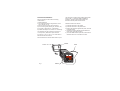
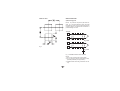
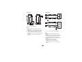
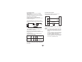
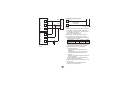
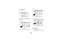
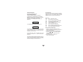
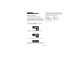
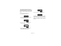
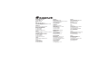
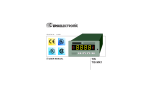
170.IU0.LHI.0A0
r USER MANUAL
LHI
INDEX
MOUNTING REQUIREMENTS .............................. 1
DIMENSIONS AND REAR TERMINALS ................ 2
PANEL CUT OUT ................................................. 3
WIRING GUIDELINES ......................................... 3
PRELIMINARY HARDWARE SETTINGS .............. 8
CONFIGURATION PROCEDURE .......................... 9
OPERATING MODE ........................................... 14
Normal display mode .................................. 14
Indicators ................................................... 14
Key functions in normal display mode ....... 14
Operative parameter display mode ............ 15
Key functions in
operative parameter display mode ............. 15
Operating parameters ................................ 16
Peak detections ......................................... 16
Alarm functions .......................................... 17
Serial link ................................................... 17
ERROR MESSAGES .......................................... 18
GENERAL SPECIFICATIONS ............................ 19
MAINTENANCE .................................................. 22
DEFAULT PARAMETERS .................................. A.1
APPENDIX B .................................................... B.1
MOUNTING REQUIREMENTS
Select a mounting location with the following
characteristics:
1) Minimal vibration.
2) An ambient temperature range between 0 and
50°C (32 and 122 °F).
3) Easy access to the rear of the instrument.
4) No corrosive gases (sulfuric gas, ammonia, etc.).
5) No water or other fluid (i.e. condensation).
6) Relative humidity of 20% to 85% non condensing.
The instrument can be mounted on a panel up to
15 mm (0.591 in) thick with a square cutout of
45 x 45 mm (1.772 x 1.772 in). For outline refer to
Dimensions and Panel Cutout.
The instrument is shipped with a rubber panel gasket
(50 to 60 Sh). To insure the IP65 and NEMA 4
protection, insert the panel gasket between the
instrument and the panel as shown below.
Install the instrument as follows:
1) Insert the instrument in the gasket.
2) Insert the instrument in the panel cutout.
3) Pushing the instrument against the panel, insert the
mounting bracket.
4) Torque the mounting bracket screws between 0.3
and 0.4 Nm (2.66 and 3.54 lbf-in).
5) To insure NEMA 4X/IP65 protection, make sure the
instrument does not move within the cutout .
Panel surface texture must be better than 6.3 µmm.
bracket
Screw
Fig. 1
Panel
Gasket
DIMENSIONS AND REAR TERMINAL BLOCKS
Without RS-485
With RS-485
Fig.2
GB 2
PANEL CUTOUT
WIRING GUIDELINES
A) Measuring Inputs
NOTE: Any external components (like Zener diodes, etc.) connected between sensor and input
terminals may cause errors in measurement due to
excessive and/or not balanced line resistance or
possible leakage currents.
TC Input
+ 10
_ 9
Shield
+ 10
Fig.3
_ 9
Shield
Fig. 4 THERMOCOUPLE INPUT WIRING
NOTE:
1) Do not run input wires with power cables.
2) For TC wiring use proper compensating cable,
preferably shielded (see Appendix B).
3) Shielded cable should be grounded at one end
only.
GB 3
LINEAR INPUT
RTD INPUT
RTD
RTD
10
9
+
_
mA,
mV
or
V
Shield
8
9
10
8
9
10
10
9
+
_
Fig. 5 RTD INPUT WIRING
mA
mV
or
V
G
NOTE:
1) Don’t run input wires together with power
cables.
2) Pay attention to the line resistance; a high line
resistance may cause measurement errors.
3) When shielded cable is used, it should be
grounded at one side only to avoid ground loop
currents.
4) The resistance of the 3 wires must be the
same.
GB 4
Fig. 6 mA, mV AND V INPUTS WIRING
NOTE:
1) Don’t run input wires together with power
cables.
2) Pay attention to the line resistance; a high line
resistance may cause measurement errors.
3) When shielded cable is used, it should be
grounded at one side only to avoid ground loop
currents.
4) The input impedance is equal to:
Less than 5 Ω for 20 mA dc input
Greater than 1 MΩ for 60 mV dc input
Greater than 400 KΩ for 5 V dc and 10 V dc
input
C.1) Relay Outputs
B) Logic Input
This input is used for remote alarm reset when
the manual reset of the alarm is selected.
Safety note:
- Do not run logic input wiring with AC power
cables.
- Use an external dry contact capable of
switching 0.5 mA, 5 Vdc.
- The instrument needs 100 ms to recognize a
contact status variation.
- The logic inputs are NOT isolated by the
measuring input.
OUT 1
1
Class 1
2
NO - OUT 1
C - OUT 1
NC - OUT 1
3
OUT 2
Class 1
(Alarm)
C
6
NO
7
Logic input
14
Fig. 8
The OUT 1 contact rating is 3A/250V AC on
resistive load.
The OUT 2 contact rating is 2A/250V AC on
resistive load.
The number of operations is 1 x 10⁵ at specified
rating.
NOTES 1) To avoid electric shock, connect power
line at the end of the wiring procedure.
2) For power connections use No 16 AWG
or larger wires rated for at last 75 °C.
3) Use copper conductors only.
4) Don’t run input wires with power
cables.
All relay contacts are protected by varistor against
inductive load with inductive component up to 0.5 A.
15
Fig.7
The following recommendations avoid serious
problems which may occur, when relay outputs
are used with inductive loads.
GB 5
C.2) Inductive Loads
High voltage transients may occur switching
inductive loads.
Through the internal contacts these transients
may introduce disturbances which can affect the
performance of the instrument.
For all the outputs, the internal protection
(varistor) assures a correct protection up to 0.5 A
of inductive component.
The same problem may occur when a switch is
used in series with the internal contacts as shown
in Fig. 9.
C
R
POWER
LINE
LOAD
Fig. 9 EXTERNAL SWITCH IN SERIES WITH
THE INTERNAL CONTACT
In this case it is recommended to install an
additional RC network across the external contact
as show in Fig. 9
The value of capacitor (C) and resistor (R) are
shown in the following table.
R
(Ω)
P.
(W)
OPERATING
VOLTAGE
<40 mA 0.047 100
22
<150 mA 0.1
0.33 47
<0.5 A
1/2
2
2
260 V AC
260 V AC
260 V AC
LOAD
(mA)
C
(µF)
The cable involved in relay output wiring must be
as far away as possible from input or communication cables.
GB 6
D) Serial Interface (option)
RS-485 interface allows to connect up to 30
devices with one remote master unit.
I
N
S
T
R
U
M
E
N
T
11
12
13
A/A'
A'/A
B/B'
B'/B
COMMON
M
A
S
T
E
R
Fig. 10 - RS-485 WIRING
The cable length must not exceed 1.5 km at 9600
BAUD.
NOTE: The following report describes the signal
sense of the voltage appearing across the
interconnection cable as defined by EIA for
RS-485.
a) The ” A ” terminal of the generator shall
be negative with respect to the ” B ” terminal
for a binary 1 (MARK or OFF) state.
b) The ” A ” terminal of the generator shall
be positive with respect to the ” B ” terminal
for a binary 0 (SPACE or ON)
I
N
S
T
R
U
M
E
N
T
I
N
S
T
R
U
M
E
N
T
E) Power Line and grounding
11
12
A/A'
B/B'
A'/A
B'/B
COMMON
13
M
A
S
T
E
R
11
12
13
Fig.11
GB 7
4
5
N, L2
POWER SUPPLY
100 to 240 Vac
24 Vac/Vdc
N, L2
R (S,T), L1
Fig.12
R (S,T), L1
NOTE:
1) Before connecting the power line, check that
the voltage is correct (see Model Number).
2) For supply connections use 16 AWG or larger
wires rated for at least 75 °C.
3) Use copper conductors only.
4) Do not run input wires with power cables.
5) Polarity does not matter for 24 Vdc wiring.
6) The power supply input is NOT fuse protected.
Please provide it externally.
Power supply
Type Current
Voltage
24 V AC/DC
T
500 mA
250 V
100/240 V AC
T
125 mA
250 V
When fuse is damaged, it is advisable to verify
the power supply circuit, so that it is necessary to
send back the instrument to your supplier.
7) Safety requirements for permanently
connected equipment:
- Include a switch or circuit-breaker in the
installation.
- Place the switch in close proximity to the
equipment and within easy reach of the
operator.
- Mark the switch as the disconnecting device
for the equipment.
NOTE: A single switch or circuit-breaker can
drive more than one instrument.
8) When the NEUTRAL line is present, connect it
to terminal 4.
9) To avoid shock and possible instrument
damage, connect power last.
PRELIMINARY HARDWARE
SETTINGS
LHI without RS-485
1) Remove the instrument from its case.
2) Set J106 according to the desired input type as
shown in the following figure.
V101
INPUT
TYPE
J106
1-2
3-4
5-6
7-8
TC-RTD close
open
open
open
60 mV
close
open
open
open
5V
open
close
open
open
10 V
open
open
close
open
20 mA
open
open
open
close
Fig.13.B
LHI with RS-485
2
4
6
8
1
3
5
7
J106
Fig.13.A
V101
GB 8
2
4
6
8
1
3
5
7
J106
CONFIGURATION PROCEDURE
CONFIGURATION KEY FUNCTIONS
RESET In Configuration Mode, used only to scroll
back parameters without to memorize a
new parameter value.
t
Used in Configuration Mode to decrease
the parameter value.
s
Used in Configuration Mode to increase
the parameter value.
FUNC Used to memorize the new parameter
value and go to the next parameter.
t + s Loads the default parameters.
s + FUNC or t + FUNC
Increases/decreases values at a higher
rate when modifying parameters.
s + RESET or t + RESET
Jumps to the Maximum or Minimum parameter value when modifying parameters.
The following is a complete list of parameters. The
lower display will show the parameter code (L1 to
d1) and the upper display will show the selection
code or numerical value. No timeout is applied in the
configuration mode.
L1 = Serial Interface Protocol
(Skipped if option is not available.)
OFF = No serial interface
nbUS= Modbus
jbUS = Jbus
L2 = Serial Link Device Address
(Skipped if option is not available or L1 = OFF)
Range: from 1 to 255
NOTE: EIA standard allows no more than 31 device
connected by one RS-485.
L3 = Baud Rate for Serial Link
(Skipped if option is not available or L1 = OFF)
Range: from 600 to 19200 baud.
(19200 baud is shown on display as 1920)
CONFIGURATION PROCEDURE
1) Remove the instrument from its case.
2) Open switch V101 (See illustrations under
“Preliminary Hardware Settings.”)
3) Re-insert the instrument in its case.
4) Switch on power to the instrument.
The upper display will show COnF.
NOTE : If "CAL" indication is displayed,
press immediately the s pushbutton and
return to the configuration procedure.
5) Press the t key and the lower display will
show the firmware version.
L4 = Byte Format for Serial Link
(Skipped if option is not available or L1 = OFF)
8E = 8 bits + even parity
8O = 8 bits + odd parity
8
= 8 bits without parity
Press the "FUNC" key to start the configuration
procedure with the first parameter (L1).
GB 9
r1 =Input Type and Range Value
0 = TC J
From
-100 to
1 = TC K
From
-100 to
2 = TC T
From
-200 to
3 = TC E
From
-100 to
4 = TC N
From
-100 to
5 = TC S
From
-50 to
6 = TC R
From
-50 to
7 = TC B
From
0 to
8 = TC L
From
-100 to
9 = TC U
From
-200 to
10 = TC G
From
0 to
11 = TC D
From
0 to
12 = TC C
From
0 to
13 = TC Plat. II From
-100 to
14 = RTD Pt 100 From
-200 to
15 = Linear
From
0 to
16 = Linear
From
12 to
17 = Linear
From
0 to
18 = Linear
From
4 to
19 = Linear
From
0 to
20 = Linear
From
1 to
21 = Linear
From
0 to
22 = Linear
From
2 to
23 = TC J
From
-150 to
24 = TC K
From
-150 to
25 = TC T
From
-330 to
26 = TC E
From
-150 to
27 = TC N
From
-150 to
28 = TC S
From
-60 to
29 = TC R
From
-60 to
30 = TC B
From
32 to
31 = TC L
From
-150 to
32 = TC U
From
-330 to
33 = TC G
From
0 to
34 = TC D
From
0 to
35 = TC C
From
0 to
36 = TC Plat. II From
-150 to
37 = RTD Pt100 From
-330 to
1000
1370
400
800
1400
1760
1760
1820
900
600
2300
2300
2300
1400
850
60
60
20
20
5
5
10
10
1830
2500
750
1470
2550
3200
3200
3300
1650
1110
4170
4170
4170
2550
1560
°C
°C
°C
°C
°C
°C
°C
°C
°C
°C
°C
°C
°C
°C
°C
mV
mV
mA
mA
V
V
V
V
°F
°F
°F
°F
°F
°F
°F
°F
°F
°F
°F
°F
°F
°F
°F
GB 10
r2 = Decimal Point Position
(Available only for linear range r1 = 15 to 22)
_ _ _ _ . = No decimal
_ _ _ . _ = One decimal figure
_ _ . _ _ = Two decimal figures
_ . _ _ _ = Three decimal figures
r3 = Initial value of the readout scale
(Available only for linear range r1 = 15 to 22)
Range: From -1999 to 9999
r4 = final value of the readout scale
(Available only for linear range r1 = 15 to 22)
Range: From -1999 to 9999
r5 = Offset Adjustment
Range: From -500 to 500
Offset value algebraically added to the measured
value.
r6 = Time constant for filter on displayed value
Range: From 0 (filter OFF) to 8 seconds.
(First order filter with selected time constant.)
r7 = Alarm action on input fault.
When the instrument detect an input failure condition, the alarm will operate as in presence of:
uP = as in presence of the full scale value.
doun = as in presence of the initial scale value.
P1 = Alarm 1 Function
nonE = Not provided
AL.P = Process alarm
Example for P2 = H.A.A.c
(Alarm
Threshold)
Alarm
Hysteresis
Alarm status *
Relay
Non alarm status
P2 = Alarm 1 configuration
(Skipped when P1 = nonE)
H.A. = High alarm with automatic reset
L.A. = Low alarm with automatic reset
H.A.Ac = High alarm with automatic reset and
"Silence" function.
L.A.Ac =Low alarm with automatic reset and
"Silence" function.
H.L. = High alarm with manual reset
L.L. = Low alarm with manual reset
FLASH
FLASH
Manual
Reset
* Alarm Status:Relay energized (P3 = dir)
Relay de-energized (P3 =rEV)
NOTE: The "Silence" function allows the manual
reset of the alarm even if the alarm condition is
still in progress.
Example for P2 = H.L.
(Alarm
Threshold)
Alarm
Hysteresis
Alarm status *
Relay
Non alarm status
(Alarm
Threshold)
Example for P2 = H.A.
Alarm
Hysteresis
FLASH
Alarm status *
Relay
Non alarm status
Manual
Reset
FLASH
FLASH
Manual
Reset
* Alarm Status:Relay energized (P3 = dir)
Relay de-energized (P3 =rEV)
FLASH
Manual
Reset
P3 = Alarm 1 Action
(Skipped when P1 = nonE)
dir = Direct action
(Relay energized in alarm condition)
rEV = Reverse action
(Relay energized in non-alarm condition)
* Alarm Status:Relay energized (P3 = dir)
Relay de-energized (P3 =rEV)
GB 11
P4 =
Alarm 1 Stand-by (mask) Function
(Skipped when P1= none)
OFF =
Stand-by function disabled
On =
Stand-by function enabled
P8 =
Alarm 2 Stand-by (mask) Function
(Skipped if option is not available or P5= nonE)
OFF =
Stand-by function disabled
On =
Stand-by function enabled
This stand-by function masks an Alarm condition
at start up until the process variable reaches the
alarm threshold plus or minus hysteresis.
This stand-by function masks an Alarm condition
at start up until the process variable reaches the
alarm threshold plus or minus hysteresis.
P5 = Alarm 2 Function
(Skipped when the option is not available)
nonE = Not provided
AL.P = Process alarm
P9 =
Delay on Stand-by (mask) Function
(This parameter is available when at least one alarm
is configured with the stand by function)
Range: from 0 (delay disabled) to 120 seconds.
P6 = Alarm 2 configuration
(Skipped if option is not available or P5 = nonE)
H.A. = High alarm with automatic reset
L.A. = Low alarm with automatic reset
H.A.Ac = High alarm with automatic reset and
"Silence" function.
L.A.Ac =Low alarm with automatic reset and
"Silence" function.
H.L. = High alarm with manual reset
L.L. = Low alarm with manual reset
NOTE: The "Silence" function allows the manual
reset of the alarm even if the alarm condition is
still in progress.
P7 = Alarm 2 Action
(Skipped if option not is available or P5 = nonE)
dir = Direct action
(Relay energized in alarm condition)
rEV = Reverse action
(Relay energized in non-alarm condition)
GB 12
At power up, this delay forces the alarms to OFF
for the programmed time and then it starts the
stand by function.
PF = Time Constant for Filter on Measured Value
for Alarms Action
(Skipped if P1 = nonE and option is not available or
P5 = nonE)
Range: From 0 (filter OFF) to 8 seconds
(First order filter with selected time constant.)
n 1 = Safety Lock
0 = UNLOCKed. The device is always
UNLOCKed and all parameters can be
modified.
l
= LOCKed. The device is always LOCKed
and no parameters can be modified
From 2 to 9999 = This number is a password, to
be used in run time (see “nn”), to LOCK/
UNLOCK the device.
t1 = Timeout Selection
tn10 =
10 second timeout
tn30 =
30 second timeout
d1 = Digital Input (contact closure)
(This is a read only parameter)
Enb =
Digital input enabled
dlS =
Digital input disabled
(The digital input is used for remote alarm reset
when the manual reset of the alarm is selected.)
The configuration procedure is now complete.
The display should show "COnF".
GB 13
OPERATING MODE
1) Remove the instrument from its case.
2) Set switch V101 (see fig. 13) to the closed
position.
3) Re-insert the instrument in its case.
4) Switch on the instrument.
Normal Display Mode
On power up the upper display shows the
measured value while the lower display shows
the engineering unit (°C or °F) (no indication
when linear input is selected); this starts is named
"Normal Display Mode."
By pressing the or key, it is possible to change
the displayed information; therefore, one of the
following display modes can be selected:
1) The upper display shows the maximum
measured value detected from the power up or
from the last peak reset.
The lower display shows "Ph."
This information is lost at power down and at
power up the device will display the process
variable.
2) The upper display shows the minimum
measured value detected from the power up or
from the last peak reset.
The lower display shows "PL."
This information is lost at power down and at
power up the device will display the process
variable.
GB 14
Indicators
“AL1” = Indicates alarm 1 status as follows:
- Flashes when alarm 1 is ON
- ON when alarm 1 has been reset but
the alarm condition is still present.
- OFF when alarm 1 is OFF
“AL2” = Indicates alarm 2 status as follows:
- Flashes when alarm 2 is ON
- ON when alarm 2 has been reset but
the alarm condition is still present.
- OFF when alarm 2 is OFF
“REM” = Indicates the remote status of the
instrument.
- Flashes when instrument is in remote
mode.
- OFF when instrument is in local mode
Key Functions in Normal Display Mode
“FUNC” = By pressing it, the display changes
from “Normal Display Mode” to “Operative Parameter Display Mode.”
= Pressing it for more than ten
seconds initiates the Lamp Test.
During the Lamp Test the device
functions normally while all
display segments and LED's are
lit with a 50% duty cycle. No
timeout is applied to a lamp test.
Press the "FUNC" key again to
end the Lamp Test.
" " or “ " = By pressing these keys it is
possible to change the displayed
information. See “Normal Display
Mode” on previous page.
“RESET” = Press and hold for 1 second to
manually reset the alarms.
“RESET” + “FUNC” = allows to clear the
maximum and minimum data hold
memories.
Operative Parameter Display Mode
The "FUNC" key initiates the Operative Parameter Display Mode when pressed for less than 10
seconds in the "Normal Display Mode."
The lower display shows the parameter code
while the upper display shows the parameter
value or status. The value of the selected
parameter can be modified with the and
keys.
Press the "FUNC" key again to store the new
value and advance to the next parameter.
If no keys are pressed within the timeout period
(see t1), the display will automatically return to
the "Normal Display Mode" in the previous display
and any modification of the last displayed
parameter will be lost.
Key Functions in
Operative Parameter Display Mode
FUNC
=
Pressing the “FUNC” key, the
instrument stores the new setting
(if changed) and goes to the next
parameter.
or
=
Changes the setting of the
selected parameter.
RESET
=
Pressing the “RESET” key, the
instrument goes back to the
previous parameter without to
store the new setting of the
selected parameter.
“RESET” + “FUNC” = allows to clear the
maximum and minimum data hold
memories.
All parameters can be modified only when the
device is UNLOCKed.
+ FUNC or
The LOCK/UNLOCK status can be selected in
configuration using “n1” parameter or during the
operating mode with the “nn” parameter
(password).
+ FUNC
Increases/decreases values at a
higher rate when modifying parameters.
+ RESET or
+ RESET
Jumps to the Maximum or Minimum
parameter value when modifying
parameters.
To switch from LOCKED to UNLOCKED, assign
to the “nn” parameter a value equal to the “n1”
parameter setting. To switch from UNLOCKED to
LOCKED, assign to the “nn” parameter any
number other than the n1 parameter setting.
When the device is in remote mode (the serial
link controls the device) no parameters can be
modified.
GB 15
OPERATING PARAMETERS
H2
Some of the following parameters may not appear,
depending on the configuration.
Alarm 2 Hysteresis (optional)
(Skipped when the option is not fitted or
P5 = nonE)
Range: From 0.1% to 10.0% of the input
span or 1 LSD
Lower Description
Display
nn
Software Key
(Skipped if n1 = 0 or 1)
ON = the device is LOCKED.
OFF = the device is UNLOCKED.
When it is desired to switch from LOCK
to UNLOCK condition, set a value equal
to “n1” parameter.
When it is desired to switch from
UNLOCK to LOCK condition, set a value
different from “n1” parameter.
A1
Alarm 1 Threshold
(Skipped when P1 =nonE)
Ranges: Span limits
A2
Alarm 2 Threshold (optional)
(Skipped when the option is not fitted or
P5 = nonE).
Ranges: Span limits
H1
Alarm 1 Hysteresis
(Skipped when P1 =nonE)
Range: From 0.1% to 10.0% of the input
span or 1 LSD
GB 16
PEAK detection
When the instrument is in normal display mode,
by pushing the s or t pushbutton it is possible
to modify the displayed information as follows:
- with the first s pushbutton pressure, the lower
display will show “PH” while the upper display
will show the maximum measured value;
- with the second s pushbutton pressure, the
lower display will show “PL” while the upper
display will show the minimum measured value;
- with the third s pushbutton pressure, the
instrument will return in normal display mode.
By the t pushbutton it is possible to display the
same informations in reverse order.
The peak memorization starts, automatically,
when switching on the instrument and cannot be
stopped.
To clear the previous values, push RESET and
FUNC pushbuttons contemporarily.
Note
Note: this visualization do not disappear after
time out. Push ▲ or ▼ pushbutton in order to
display the measured value.
Alarm functions
The alarms can be programmed as automatic or
manual reset or the “Silence” function.
The "Silence" function is a typical function of the
alarm annunciators (see ISA “Alarm annunciator
operational sequence”) and it is usually applied to
audible alarm indications (horn). This function
allows the manual reset of the alarm even if the
alarm condition is still in progress.
It is also possible to assign to the alarm a stand
by (mask) function.
This function masks the alarm condition at
instrument start-up until process variable reaches
the alarm threshold plus or minus hysteresis.
Graphic examples of the alarm behaviour are
shown at page 11.
Serial Link (optional)
The device can be connected to a host computer via
serial link.
The host can put the device in LOCAL (parameters
are controlled via keyboard) or in REMOTE (functions and parameters are controlled via serial link).
REMOTE is shown by the decimal point to the
left of "RMT" which is on the right side of the
numeric display.
Via serial link it is possible to read and/or to modify
all the operative and configuration parameters.
The following conditions must apply to implement
this function:
1) Configure parameters L1 through L4 with the
front keyboard
2) The device must be in the Operating mode.
For other detailes require ENG 818-E document.
GB 17
ERROR MESSAGES
Overrange, Underrange and
Sensor Break Indications
This device detects input fault conditions.
(OVERRANGE, UNDERRANGE OR SENSOR
BREAK). When the process variable exceeds the
span limits established by configuration
parameter r1 an OVERRANGE condition will
appear as:
An UNDERRANGE condition will appear as:
A sensor break is signalled as "OPEN”. On the mA/
V input, a sensor break can be detected only when
the range selected has a zero elevation (4/20 mA,
12/60 mV, 1/5 V or 2/10 V.)
On the RTD input "shrt" is signalled when input
resistance is less than 15 Ω (short circuit sensor
detection).
This device detects reference junction errors or
errors on the internal autozero measurement. When
a fault is detected the alarms assume an upscale/
downscale reading in accordance with r7.
GB 18
Error Messages
On power up, the instrument performs a self-diagnostic test. When an error is detected, the lower
display shows an "Er" indication while the upper
display shows the code of the detected error.
Error List
100
Error in EEPROM writing
150
Short circuit on CPU's outputs
200
Error on "protect register" in EEPROM
XXX
Configuration parameter error.
301
Error on calibration of selected input.
307
rj input calibration error.
400
Error on operative parameter.
500
Error on autozero measurement.
502
Error on reference junction measurement.
510
Error during calibration procedure.
Dealing with Error Messages
1) When a configuration parameter error is
detected, repeat the configuration procedure of
that specific parameter.
2) If an error 400 is detected, simultaneously
press the and keys to load the default
parameters and then repeat the control
parameter setup.
3) For all other errors, contact your
Service Representative.
GENERAL SPECIFICATIONS
Case: Polycarbonate grey case
Self extinguishing degree: V-0 according to UL.
Front protection - designed and tested for IP 65 (*)
and NEMA 4X (*) for indoor locations (when panel
gasket is installed).
(*) Test were performed in accordance with IEC
529, CEI 70-1 and NEMA 250-1991 STD.
Installation: panel mounting.
Rear terminal board: 15 screw terminals (screw
M3, for cables from f 0.25 to f 2.5 mm2 or from
AWG 22 to AWG 14 ), connection diagram and
safety rear cover.
Dimensions: 48 x 48 mm (according to DIN
43700); depth
- 122 mm for models with RS-485.
- 105 mm for models without RS-485
Weight: 250 g. max. (8.75 oz.).
Power supply : (switching mode) from 100 to
240 V AC. 50/60 Hz (+10 % to -15 % of the
nominal value) or
24 V DC/AC (+10 % of the nominal value).
Power consumption: 8 VA.
Insulation resistance: > 100 MΩ according to
IEC 1010-1.
Isolation voltage: 1500 V r.m.s. according to IEC
1010-1.
Common mode rejection ratio:
120 dB @ 50/60 Hz.
Normal mode rejection ratio: 60 dB @ 50/60 Hz.
Electromagnetic compatibility and safety
requirements: This instrument is marked CE.
Therefore, it is conforming to council directives
89/336/EEC (reference harmonized standard
EN 50081-2 and EN 50082-2) and to council
directives 73/23/EEC and 93/68/EEC (reference
harmonized standard EN 61010-1).
Installation category: II
GB 19
D/A conversion: dual slope integration.
Sampling time :
- for linear inputs = 250 ms.
- for TC or RTD inputs = 500 ms.
Display updating time: 500 ms.
Resolution: 30000 counts.
Temperature Drift
- Less than 200 ppm/°C of full span for mV and
TC ranges 0, 1, 3, 4, 8, 13, 23, 24, 26, 27, 31,
36 (CJ excluded).
- Less than 300 ppm/°C of full span for mA, V and
TC ranges 10, 11, 12, 33, 34, 35 (CJ excluded)
- Less than 400 ppm/°C of full span for RTD and
TC range 9, 32 (CJ excluded).
- Less than 500 ppm/°C of full span for TC ranges
2, 5, 6, 25, 28, 29 (CJ excluded).
- Less than 600 ppm/°C of full span for TC ranges
7, 30.
NOTE: Precision and drift guaranteed (for
T>300°C/570°F).
Accuracy: + 0.2% f.s.v. @ 25 °C and nominal
power supply voltage.
Operative temperature: from 0 to +50 °C (32 to
122 °F).
Storage temperature: from -20 to +70 °C (-4 to
158 °F).
Humidity: from 20% to 85 % RH not condensing.
INPUTS
A) THERMOCOUPLE
Type : J, K, T, E, N, S, R, B, L, U, G(W), D(W3),
C(W5), Platinel II, °C/°F selectable.
External resistance: 100 Ω max, maximum error
0,1% of span.
Burn out: It is shown as an overrange condition
(standard). It is possible to obtain an underrange
indication by cut and short.
Cold junction: automatic compensation from 0 to
50 °C.
Cold junction accuracy : 0.1 °C/°C
Input impedance: > 1 MΩ
Calibration : according to IEC 584-1 and DIN
43710 - 1977.
STANDARD RANGES TABLE
T/C
type
J
K
T
E
N
S
R
B
L
U
G(W)
D(W3)
C(W5)
P.(*)
Ranges
0
1
2
3
4
5
6
7
8
9
10
11
12
13
-100 / 1000
-100 / 1370
-200 / 400
-100 / 800
-100 / 1400
-50 / 1760
-50 / 1760
0 / 1820
-100 / 900
-200 / 600
0 / 2300
0 / 2300
0 / 2300
-100 / 1400
°C
°C
°C
°C
°C
°C
°C
°C
°C
°C
°C
°C
°C
°C
23
24
25
26
27
28
29
30
31
32
33
34
35
36
-150 / 1830
-150 / 2500
-330 / 750
-150 / 1470
-150 / 2550
-60 / 3200
-60 / 3200
32 / 3300
-150 / 1650
-330 / 1110
0 / 4170
0 / 4170
0 / 4170
-150 / 2550
°F
°F
°F
°F
°F
°F
°F
°F
°F
°F
°F
°F
°F
°F
(*) P. equal to Platinel II
GB 20
B) RTD (Resistance Temperature Detector)
Input: for RTD Pt 100 Ω, 3 wire connection.
Input circuit: current injection.
°C/°F selection: via front pushbuttons or serial link.
Line resistance: automatic compensation up to 20
Ω/wire with no measurable error.
Calibration: according to DIN 43760
Burn out : The instrument detect the open condition
of one or more wires. It is able to detect also the
short circuit of the sensor.
STANDARD RANGES TABLE
Input
type
Ranges
RTD Pt 100 Ω
14
- 200 / 850
°C
DIN 43760
37
- 330 / 1560
°F
C) LINEAR INPUTS
Read-out: keyboard programmable between
-1999 and +9999.
Decimal point: programmable in any position
Burn out: the instrument shows the burn out
condition as an underrange condition for 4-20
mA, 1-5 V and 2-10 V input types.
It shows the burn out condition as an underrange
or an overrange condition (selectable by
soldering jumper) for 0-60 mV and 12-60 mV
input types. No indication are available for 0-20
mA, 0-5 V and 0-10 V input types.
STANDARD RANGES TABLE
Input type
15
16
17
18
19
20
21
22
0 - 60 mV
12 - 60 mV
0 - 20 mA
4 - 20 mA
0- 5 V
1- 5 V
0 - 10 V
2 - 10 V
Impedance
OUTPUTS
Accuracy
Output updating time :
- 250 ms when a linear input is selected
- 500 ms when a TC or RTD input is selected.
> 1 MΩ
<5Ω
0.2 % + 1 digit
@ 25°C
> 400 kΩ
> 400 kΩ
Output 1
Type: relay SPDT contact .
Contact rated: 3 A at 250 V AC on resistive load.
Function: Alarm output
Action: direct/reverse programmable by front
keyboard.
Output 2
Type: relay SPST contact .
Contact rated: 2 A at 250 V AC on resistive load.
Function: Alarm output
Action: direct/reverse programmable by front
keyboard.
E) LOGIC INPUT
This instrument is provided of 1 logic input used
for remote alarm reset.
NOTES:
1) Use an external dry contact capable of
switching 0.5 mA, 5 V DC.
2) The instrument needs 100 ms to recognize a
contact status variation.
3) The logic inputs are NOT isolated by the
measuring input.
ALARMS
Action: Direct or reverse acting.
Alarm functions: process alarm.
Operative mode : High or low programmable.
Threshold : programmable in engineering unit within
the input span.
Hysteresis: programmable from 0.1 % to 10.0 % of
the input span.
Alarm reset: automatic reset, manual reset or
"Silence" function is programmable.
Stand by (mask) alarm: the alarm can be
configured with or without stand by (mask)
function.
GB 21
SERIAL COMMUNICATION INTERFACE
(OPTION)
Type: Isolated RS-485
Protocol type: MODBUS or JBUS.
Baud rate: programmable from 600 to 19200
BAUD.
Byte format: 8 bit.
Parity: even, odd or none programmable.
Stop bit: one.
Address: from 1 to 255.
Output voltage levels: according to EIA
standard.
MAINTENANCE
1) REMOVE POWER FROM THE POWER
SUPPLY TERMINALS AND FROM RELAY
OUTPUT TERMINALS
2) Remove the instrument from case.
3) Using a vacuum cleaner or a compressed air
jet (max. 3 kg/cm2) remove all deposit of dust
and dirt which may be present on the louvers
and on the internal circuits trying to be careful
for not damage the electronic components.
4) To clean external plastic or rubber parts use
only a cloth moistened with:
- Ethyl Alcohol (pure or denatured) [C2H5OH] or
- Isopropil Alcohol (pure or denatured)
[(CH3)2CHOH] or
- Water (H2O)
5) Verify that there are no loose terminals.
6) Before re-inserting the instrument in its case,
be sure that it is perfectly dry.
7) re-insert the instrument and turn it ON.
GB 22
APPENDIX A
DEFAULT PARAMETERS
is complete and the instrument reverts to the “Normal
Display Mode.” The following is a list of the default
operating parameters loaded during the procedure:
DEFAULT PARAMETERS
Default Operating Parameters List
Parameter
Default Value
Software Key
Unlock
Alarm 1 Threshold
Initial scale value
Alarm 2 Threshold
Initial scale value
Alarm 1 Hysteresis
0.1%
Alarm 2 Hysteresis
0.1%
Loading Default Operating Parameters
The control parameters can be loaded with predetermined default values. These are the settings
loaded into the instrument prior to shipment from the
factory. To load the default values proceed as
follows:
a) Press and hold the key and press the
key; the displays will show:
b) Press either the
show:
or
key; the display will
c) Press the "FUNC" key; the display will show:
This indicates that the loading procedure has been
initiated. After about 3 seconds the loading procedure
Appendix A.1
Loading Default Configuration Parameters
The configuration parameters can be loaded with
predetermined default values. These are the settings
loaded into the instrument prior to shipment from the
factory. To load the default values proceed as
follows:
f) Press the FUNC key; the display will show:
a) Internal switch V101 must be open.
b) The upper display will show:
c) Press the key; the lower display will show
the firmware version.
d) Still holding the key, press the
display will show:
This indicates that the loading procedure has been
initiated. After about 3 seconds the procedure is
complete and the instrument reverts to the “COnF”
display. The following is a list of the default
configuration parameters loaded during the
procedure:
key; the
e) Press the
key to select Table 1 (European) or Table 2 (American) default
parameters; the display will show:
Appendix A.2
Table 1
Table 2
European
American
L1
nbUS
nbUS
L2
1
1
L3
19200
19200
L4
8E
8E
r1
Type J
Type J
(-100 to 1000 °C)
(-150 to 1830 °F)
r2
----.
----.
r3
-100
-150
r4
1000
1830
r5
0
0
r6
1 second
1 second
r7
uP
uP
P1
AL.P
AL.P
P2
H.A.
H.A.Ac
P3
rEV
rEV
P4
OFF
OFF
P5
nonE
nonE
P6
H.A.
H.A.Ac
P7
rEV
rEV
P8
OFF
OFF
P9
0 seconds
0 seconds
PF
1 second
1 second
n1
0
0
t1
10 seconds
30 seconds
PARA.
Appendix A.3
APPENDIX B
THERMOCOUPLE COMPENSATING CABLE COLOR CODES.
British
Thermocouple
BS 1843
Material
T Copper Constantan + White
- Blue
Blue
+ Yellow
J/L Iron Constantan
- Blue
Black
+ Brown
K Nickel Chromium
- Blue
Nickel Aluminum
Red
+ White
R Platinum/Platinum
- Blue
13% Rhodium
Green
+ White
S Platinum/Platinum
- Blue
10% Rhodium
Green
+ Brown
E Chromel
- Blue
Constantan
Brown
–
B Platinum 30% Rh
–
Platinum 6% Rh
–
N Nicrosil / Nisil
American
ANSI MC 96.1
+ Blue
- Red
Blue
+ White
- Red
Black
+ Yellow
- Red
Yellow
+ Black
- Red
Green
+ Black
- Red
Green
+ Violet
- Red
Violet
+ Grey
- Red
Grey
–
German
DIN 43710
+ Red
- Brown
Brown
+ Red
- Blue
Blue
+ Red
- Green
Green
+ Red
- White
White
+ Red
- White
White
–
–
Appendix B.1
–
–
–
–
French
NFE 18-001
+ Yellow
- Blue
Blue
+ Yellow
- Black
Black
+ Yellow
- Purple
Yellow
+ White
- Green
Green
+ White
- Green
Green
–
–
–
–
–
–
Ero Electronic S.r.l.
Via E. Mattei, 21
28100 Novara
Italy
Tel. +39 0321481111
Fax +39 0321481112
[email protected]
BENELUX
ERO Electronic Benelux SA/NV
Rue Val Notre Dame 384
MOHA 4520 (WANZE)
Tel. 085-274080
Fax 085-274081
[email protected]
BRASIL
ERO ELECTRONIC DO BRASIL Industria
e Comercio Ltda.
Rua Garibaldi, 659 - Conj. 202
90035-050 PORTO ALEGRE
Tel. 051-2214888
Fax 051-2214734
[email protected]
CHINA
TIANJIN VEGA COMPANY Ltd
(TAIF)
Hebei District
300232 TIANJIN
Tel. 022-26273296
Fax 022-26273297
FRANCE
ERO Electronic SARL
Zac du Chêne
34, Rue du 35éme Régiment d’Aviation
69673 BRON CEDEX
Tel. 0478267979
Fax 0478267800
SPAIN
ERO ELECTRONIC IBERICA
Calle La granja, 74
Pol. Ind. Alcobendas
MADRID
Tel. 091-6618194
Fax. 091-6619093
GERMANY
ERO Electronic GmbH
Ottostrasse 1
65549 LIMBURG A.D. LAHN
Tel. 06431-95680
Fax 06431-57493
U.K.
ERO U.K.
Unit 1, Cygnet Trading Estate
Faraday Close
Durrington, Worthing
WEST SUSSEX BN13 3RQ
Tel. 01903-693322
Fax. 01903-693377
NETHERLAND
ERO Electronic Nederland
Ganieelan 4
2404 CH Alphen a/d Rijn
Tel. 0172-420400
Fax. 0172-420395
[email protected]
SOUTH AFRICA
ERO Electronic S.A. Pty Ltd
Airgro House
1343, Spokeshave Avenue
Stormill Ext 2 ROODEPOORT
Tel. 011-4742278/9
Fax 011-4749404
P.O. Box 43112
Industria 2042
[email protected]
U.S.A.
AMERICAN ERO Electronic Corp
BARRINGTON, ILL. 60010
Tel. 0847-382-0881
Fax 0847-382-0240
U.S.A.
BARBER COLMAN
Industrial Instruments Div.
P.O. BOX 2940
Loves Park, IL - 31132 - 2940
Tel. 0815-637-3000
Fax 0815-637-5341
[email protected]