1
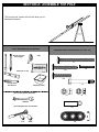
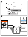
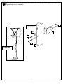
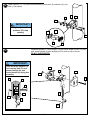
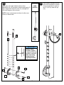
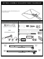
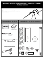
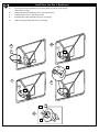
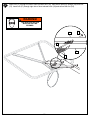
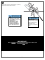
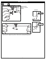
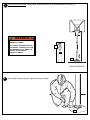
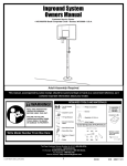
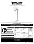
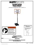
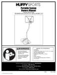
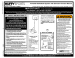
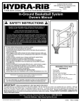
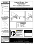
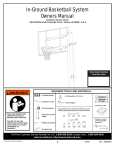
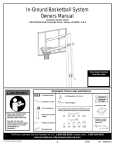
Inground System
Owners Manual
Customer Service Center
• N53 W24700 South Corporate Circle • Sussex, WI 53089 • U.S.A.
REQUIRED TOOLS AND MATERIALS:
• 2 People
• Phillips Screwdriver
• Carpenter’s Level
• Hammer
•
WARNING!
READ AND UNDERSTAND
OPERATOR'S MANUAL
BEFORE USING THIS UNIT.
FAILURE TO FOLLOW
OPERATING INSTRUCTIONS
COULD RESULT IN INJURY
OR DAMAGE TO PROPERTY.
• Heavy Duty Tape
• Container to Mix
• 15’ Tape Measure
• Stepladder 8 ft. (2.4 m)
• Shovel & Post Hole
Digger
• Safety Goggles
• Wood Board (scrap)
• (2 each) Wrenches and/or Socket Wrenches and
Sockets (Deep-Well Sockets are Recommended).
• Tape
7/16"
1/2"
9/16"
3/4"
• Optional: Large &
Small Adjustable
Wrenches
• Sawhorse or
Support Table
• Wedge
7/16"
1/2"
9/16"
3/4"
Toll-Free Customer Service Number for U.S: 1-800-558-5234,
For Canada: 1-800-284-8339,
For Europe: 00 800 555 85234 (Sweden: 009 555 85234),
For Australia: 1-800-632 792
Internet Address: http://www.huffysports.com
© COPYRIGHT 2004 by HUFFY SPORTS
1
10/04
P/N 21196804
BEFORE YOU START!
35
To ensure optimal playability of backboard system, a
close tolerance fit between the elevator components
and hardware is required. Test-fit large bolts into large
holes of elevator tubes, backboard brackets, and
triangle plates. Carefully rock them in a circular
motion to ream out any excess paint from holes if
necessary.
HEIGHT ADJUSTMENT
1
TO ADJUST BACKBOARD:
3
1. While holding handle, remove pin.
2. Move elevator up or down to
desired height.
2
3. Replace pin full length to lock
system at desired height.
Not all items pictured are included with every model.
2
201251
P/N 21196804 10/04
2
2/99
PARTS LIST - See Hardware Identifier
Item Qty. Part No. Description
1
2
3
4
5
6
7
8
9
10
11
12
13
14
15
16
17
18
19
20
21
22
23
24
25
26
27
1
1
1
2
1
1
2
9*
4
4
4
2
2
2
1*
1
1
1
1
2
1
4
4
6
2
1
6
908123
908125
908124
202800
202801
204832
203053
203100
206360
203232
203063
204858
204857
204859
203038
204850
204853
908152
204872
203103
204803
202862
206311
206340
900964
207103
206244
Item Qty. Part No. Description
Top Pole Section
Middle Pole Section
Bottom Pole Section
Ground Sleeve
Ground Sleeve Cap
Bracket, Pole Mount
Carriage Bolt, 5/16-18 x 4 Long
Hex Flange Nut, 5/16-18
Bolt, Hex Head, 3/8-16 x 2-5/8 Long
Washer, Metal, 3/4” O.D.
Nut, Nylock, Hex Head, 3/8-16
Spacer, Biscuit, Plastic
Spacer, Metal 1/2” O.D. x 1.44 Long
Cover, Spring
Carriage Bolt, 5/16-18 x 2-3/4 Long
Pin, Locking
Lanyard, Black Coil
Height Adjustment Rod
Label, Height Indicator
Carriage Bolt, 5/16-18 x 2 Long
Screw, Phillips Head
Spacer, .563 ID x 1.190 Long
Spacer, .53 I.D. x .65 O.D. x .5 Long
Lock Nut,1/2-13
Board Bracket
Cap,Pole, 3.5" X .75"
Bolt, Hex Head 1/2-13 x 8 Long
28
29
30
31
32
33
34
35
36
37
38
39
40
41
42
43
44
45
46
47
48
49
50
2
2
2
2
1
12*
1
1
1
1
1
2
1
1
1
1
1
1
1
4
1
1
2
900183
204838
904807
200874
201219
201251
203279
204855
204856
201683
206990
900033
203796
200318
203472
203470
203795
205528
206118
903601
204159
Elevator Tube, Lower-Long
Spring
Elevator Tube, Upper-Short
Spacer, Metal .402 I.D. x .50 O.D. x 1.5
Rim
Smart Clip
Net
Label, Height Adjustment
Anti-Skid Tape
Handle, Left
Handle, Right
Spacer, Black, 1.5 Long
Bracket Reinforcement
Slam Jam Bracket, Black
Bolt, “Tee” 3/8 - NC x 5 Long
Bracket Reinforcement, Slam Jam
Spring, Black
Washer, Flat 5/8 I.D. x 1-1/2 O.D.
Nut, Special 3/8-NC
Bolt, Hex-Flange 5/16-18 x 1" Long
Warning Label
Rebar
Rebar Centering Spacer
* YOU MAY HAVE EXTRA PARTS WITH THIS MODEL.
NOTICE TO ASSEMBLERS
ALL Huffy Sports Basketball Systems, including those used for DISPLAYS, MUST be assembled and
ballasted with sand, water or concrete according to the instructions. Failure to follow instructions
could result in SERIOUS INJURY. It is NOT acceptable to devise a makeshift weight system.
IMPORTANT!
Remove all contents from boxes.
Be sure to check inside pole sections;
hardware and additional parts are
packed inside.
WARRANTY CARD:
Please remember to complete your product
registration form either on-line at:
www.huffysports.com or mail-in the
enclosed postcard.
For more information on assembly, placement, proper
use, and maintenance, visit The American Basketball
Council website at http://www.smarthoops.com.
3
10/04
P/N 21196804
SAFETY INSTRUCTIONS
FAILURE TO FOLLOW THESE SAFETY INSTRUCTIONS MAY RESULT IN
SERIOUS INJURY, PROPERTY DAMAGE AND WILL VOID WARRANTY.
Owner must ensure that all players know and follow these rules for safe
operation of the system.
To ensure safety, do not attempt to assemble this system without following
the instructions carefully. Proper and complete assembly, use and
supervision is essential for proper operation and to reduce the risk of
accident or injury. A high probability of serious injury exists if this system is
not installed, maintained, and operated properly. Check entire box and inside
all packing material for parts and/or additional instructional material. Before
beginning assembly, read the instructions and identify parts using the
hardware identifier and parts list in this document.
• If using a ladder during assembly, use extreme caution.
• Two (2) people are reccomended for this operation.
• Seat the pole sections properly. Failure to do so could allow the pole
sections to separate during play.
• Before digging, contact utility company to locate underground power
cables, gas, and water lines. Ensure there are no overhead power lines
within 20 ft. (7 m) radius of pole location.
• Climate, corrosion, excessive use, or misuse could result in system failure.
• If technical assistance is required, contact Huffy Sports.
• Minimum operational height is 6'6" (1.98 m) to the bottom of backboard.
• This equipment is intended for home recreational use only and NOT
excessive competitive play.
• Read and understand the warning label affixed to pole. Label is shown
below
• The life of your basketball pole depends on many conditions. The climate,
placement of the pole, the location of the pole, exposure to corrosives such
as pesticides, herbicides, or salts are all important.
• Adult supervision is recommended when adjusting height.
• Serious injury could occur if teeth/face come in contact with backboard,
net, or rim.
Most injuries are caused by misuse and/or not following instructions.
Use caution when using this system.
P/N 21196804 10/04
4
HARDWARE IDENTIFIER (BOLTS & SCREWS)
#21 (1)
#7 (2)
#15 (1)*
#20 (2)
#9 (4)
#47 (4)
#42 (1)
HARDWARE IDENTIFIER (NUTS & WASHERS)
#27 (6)
#8 (9)*
#11 (4)
#24 (6)
#10 (4)
#46 (1)
#45 (1)
HARDWARE IDENTIFIER (METAL SPACERS)
#13 (2)
#31 (2)
* You may have extra parts with this model.
5
10/04
P/N 21196804
HARDWARE IDENTIFIER (PLASTIC SPACERS & CLIPS)
#22 (4)
#12 (2)
#23 (4)
#39 (2)
#33 (12)*
HARDWARE IDENTIFIER (OTHER)
#41 (1)
#43 (1)
#44 (1)
P/N 21196804 10/04
6
SECTION A: ASSEMBLE THE POLE
This is what your system will look like when you’ve
finished this section:
TOOLS REQUIRED FOR THIS SECTION
Shovel and Post
Hole Digger
HARDWARE USED IN THIS SECTION (not actual size)
Tape
#7
#21
#15
Carpenter's Level
#20
Phillips-Head
Screwdriver
#9
Container to Mix
(2) 1/2” and (2) 9/16" Wrenches
#8
#11
AND/OR
(2) Socket Wrenches and Sockets
#13
1/2”
9/16”
#12
7
10/04
P/N 21196804
1.
Mark pole sections with tape (not supplied) at indicated distances from ends as shown.
TOP
1
MIDDLE
2
Tape (Not Supplied)
BOTTOM
2.
3
Ensure ground is level with playing surface, then dig pole hole.
IMPORTANT!:
WARNING!
Maximum distance from
edge of hole to edge of
playing surface 6”
(15.2 cm).
18" (42.7 cm)
GROUND SURFACE
6" (15.2 cm)
CONTACT UTILITIES
BEFORE DIGGING.
PLAYING SURFACE
24" (61 cm)
P/N 21196804 10/04
8
3.
4.
Snap two halves of
ground sleeve (4)
together.
Fill hole approximately 1/3
full with mixed concrete.
Insert and secure
bottom pole section
(3) into ground sleeve
(4) by tightening
ground sleeve cap (5).
NOTE: Flared end
goes inside ground
sleeve.
5.
FIG. A
Insert ground sleeve assembly and center
in hole (FIG. A).
Note: Leave 1" below flange exposed
for drainage hill.
4
SIDE VIEW
PLAYING SURFACE
FLANGE
1" (2.54 cm)
3
IMPORTANT!:
NOTE POSITION OF
FLANGE
5
4
IMPORTANT!:
CONTINUE ON TO NEXT STEP.
DO NOT WAIT FOR CONCRETE TO CURE.
9
10/04
P/N 21196804
6.
Fill hole completely with concrete.
3
1" (2.54 cm)
5
4
IMPORTANT!:
CONTINUE ON TO NEXT STEP.
DO NOT WAIT FOR CONCRETE TO CURE.
Tamp down concrete to release air pockets and build drainage hill. Level pole section in all directions
several times while concrete is curing.
7.
NOTE A:
DRAINAGE HILL
Make a reference mark
here for anti-skid tape.
1" (2.54 cm)
NOTE B:
PLAYING SURFACE
1" (2.54 cm)
Keep flange pushed down
to concrete and leveled.
SIDE VIEW
IMPORTANT!:
WAIT A MINIMUM OF 24 HOURS BEFORE GOING ON TO NEXT STEP.
CONCRETE MUST CURE.
P/N 21196804 10/04
10
8.
After concrete has cured, remove bottom pole section from ground sleeve (4). Place anti-skid tape (36)
around the bottom area of bottom pole (see note A).
KEEP GROUND SLEEVE CAP ON BOTTOM POLE.
NOTE A:
Place top edge of anti-skid
tape on mark made in
step 7.
36
5
NOTE B:
4
Tape prevents the pole
from rotating during play.
11
10/04
P/N 21196804
9.
Stack and bounce bottom (3) and middle (2)
pole sections together. Bounce pole sections
together until middle section no longer moves
toward taped reference mark on bottom pole.
10.
Stack upper pole section (1) to bottom and middle
pole assembly and continue bouncing until top pole
(1) no longer moves toward taped reference mark on
middle pole.
5"
(12.7 cm)
Tape
1-1/2"
(3.81 cm)
Tape
5"
(12.7 cm)
Tape
1-1/2"
(3.81 cm)
Tape
1
The warning
label should be
90 degees from
uppermost holes
on top pole (1) see Illustration.
2
Taped reference marks
IMPORTANT
5
Keep on Bottom Pole
Wood Scrap
(NOT
SUPPLIED)
3
5
WARNING
FAILURE
TO
IN SERIOUSFOLLOW
THESE
INJURY
WARNINGS
AND/OR
Owner
PROPERTYMAY RESULT
must
DAMAGE.
these ensure that
rules
for safe all players
• DO NOT
operation know and
follow
of the
includingHANG on the
system.
• During backboard, rim or any
part
play,
activities, especiallysupport braces of the system
or net.
and net. keep player'swhen performing
contact Serious injury face away
dunk
type
• Do not with backboard,could occurfrom the backboard,
if teeth/face
rim
• After slide, climb,
rim
assembly
shake or net.
come
or
water
in
or sand is complete, play on base
in an upright
and stake
fill system and/or
position to the ground. completelypole.
system
with
• When may tip over without filling Never
adjusting
causing
base withleave system
fingers
injuries.
height
weight,
or moving
• Do not away from
as
moving
system,
• During allow children
parts.
keep hands
play,
etc.). Objectsdo not to move or
and
wear jewelry adjust
• Surface
system.
may entangle
(rings,
watches,
gravel beneath the
in
or
base mustnet.
necklaces,
could other sharp
be smooth
• Keep cause system objects. Punctures
and free
organic
to
of
etc. could material tip over.
cause
leakage
away
• Check cause corrosion
from pole
and
pole
base.
chipping) system
and/or
Grass,
for
deterioration.
litter,
penetratedand repaint signs of corrosion
immediately.through with exterior
(rust,
the steel
pitting,
enamel
• Check
anywhere, paint.
system
replace If rust has
hardware,
before
pole
before excessive each use for
wear and
proper
• Check use.
ballast,
signs
corrosion loose
• Do not system before
and repair
use
conditions; system each use for
during
system
windy instability.
storage
and/or
may
severe
and freeposition and/or tip over.
• Never from personal in an areaPlace system weather
• See play on damagedproperty protected in the
from
instruction
and/or
maintenance. manual equipment. overhead the wind
wires.
for proper
• When
moving
installation
shifting.
system,
and
use caution
• Keep
pole
to keep
• Do not top covered
mechanism
allow
with
water
weather
from
in tank cap at all times.
add non-toxic
to freeze.
completely
antifreeze, During
and
• Use
extreme store. (Do
sand or sub-freezing
not
caution
System
empty
if placinguse salt.)
may tip
tank
over more
system
on sloped
easily.
surface.
Wood Scrap
(NOT
SUPPLIED)
In the
U.S.:1-800-558-5234
and Canada:
1-800-284-8339
201241
2/99
IMPORTANT!:
POLE SECTIONS
SHOULD HAVE A
3-1/2" (9 CM)
MINIMUM OVERLAP.
P/N 21196804 10/04
IMPORTANT!:
12
11.
Install pole mount bracket (6) and bracket reinforcement (40) with carriage bolts (7) as shown.
Tighten flange nuts (8) completely.
8
FRONT SIDE
40
6
7
7
1
FRONT SIDE
13
10/04
P/N 21196804
12.
Attach spacers (12, 13) to pole mount bracket (6) with bolts (9), washers (10), and
nuts (11) as shown.
6
10
10
11
IMPORTANT!:
Tighten just until
washers (10) stop
moving.
13
12
9
13
12
Assemble lanyard (17) to locking pin (16) as shown. Attach covers (14) onto
pole mount bracket (6) with carriage bolt (15) and nut (8) as shown.
DO NOT OVERTIGHTEN
13.
IMPORTANT!:
Loop end of pin lanyard (17)
over carriage bolt (15) as it
passes through the pole
mount bracket (6) during this
assembly.
14
14
6
15
6
15
17
14
8
17
16
P/N 21196804 10/04
14
8
14
14.
15.
SIDE
ACCESS
Apply logo and height indicator labels (19) to
adjustment rod (18) as shown. Attach handle parts (37,
38) to adjustment rod with screw (21), carriage bolt
(20), and flange nut (8) as shown.
Insert handle assembly through
pole mount assembly as shown.
Lock pole assembly in place at
the 10’ (3.05 m) mark with pin
(16).
NOTE: Holes in adjustment rod allow for either rear
access or side access.
16
18
19
IMPORTANT!:
Indicator labels
should be applied
as close to holes as
possible to prevent
labels from being
damaged during
height adjustment.
38
20
8
37
20
21
15
10/04
P/N 21196804
SECTION B: ASSEMBLE THE ELEVATOR TUBES TO BACKBOARD
This is what your system will look like when you’ve
finished this section:
TOOLS REQUIRED FOR THIS SECTION
HARDWARE USED IN THIS SECTION (not actual size)
(2) Wrenches 1/2", (2), 9/16"" and (2) 3/4"
#9
#47
#24
AND/OR
#27
(2) Socket Wrenches and Sockets
#11
#42
#31
1/2”
9/16”
3/4”
#22
#8
#41 (1)
Identify elevator tubes (28 & 30).
Toward
Board
Toward
Pole
Upper Elevator tube
30
Toward
Pole
Toward
Board
Lower Elevator tube
P/N 21196804 10/04
16
28
1.
Attach backboard support brackets (25) to the backboard
frame using bolts (9), spacers (31), and nuts (11) as shown.
31
11
31
11
25
9
9
2.
Attach lower elevator tubes (28) and springs (29) to backboard support brackets (25) using spacers (22),
bolt (27), and nut (24) as shown. Insert T-bolt (42) into Slam Jam bracket (41) then, attach that assembly
to board using bolts (47) and nuts (8)
8
24
22
25
29
22
29
27
28
42
41
41
42
47
17
10/04
P/N 21196804
3.
Attach upper elevator tubes (30) to backboard support brackets (25) using spacers (22), bolt (27), and nut
(24) as shown.
25
24
22
29
22
30
27
28
30
28
P/N 21196804 10/04
18
SECTION C: ATTACH THE BACKBOARD & ELEVATOR ASSEMBLY
TO POLE SYSTEM
This is what your system will look like when you’ve
finished this section:
TOOLS REQUIRED FOR THIS SECTION
HARDWARE USED IN THIS SECTION (not actual size)
Container to Mix
Phillips-Head
Screwdriver
#27
(2) 3/4" Wrenches
#43
#45
AND/OR
#44
(2) Socket Wrenches and Sockets
#24
#46
#33
3/4”
#23
19
#39
10/04
P/N 21196804
1.
Support pole on sawhorse. Attach backboard assembly to top pole section (1).
24
24
WARNING!
30
USE CAUTION; ELEVATOR
ASSEMBLY IS HEAVY.
28
TWO PEOPLE REQUIRED FOR THIS
PROCEDURE. FAILURE TO
FOLLOW THIS WARNING COULD
RESULT IN SERIOUS INJURY
AND/OR PROPERTY DAMAGE.
23
1
23
23
23
30
28
27
27
2.
Install handle assembly to long elevator
tubes (28) using bolt (27), spacers (39),
and nut (24) as shown.
39
24
28
39
NOTE:
Before going on to
next step, set
adjustable system
assembly to the 10’
(3.05 m) setting.
P/N 21196804 10/04
27
20
28
3.
Install Slam Jam Rim to Backboard
A
•
B
•
Fit rim (32) securely into bracket (41) as shown (Allow "T"-bolt (42) to slip through
center hole in rim (32).
Install reinforcement bracket (43) onto “T” bolt (42) as shown.
C
•
Install spring (44) onto “T” bolt (42) as shown.
D
•
Install special nut (46) and washer (45) onto “T” bolt (42).
E
•
Tighten nut (46) until flush with end of “T” bolt (42).
B
A
43
32
42
42
41
46
C
45
D
44
42
42
45
E
46
21
10/04
P/N 21196804
4.
Insert bolt (27) through left side of short elevator tube (30), then stretch spring or springs (29) onto bolt
(27). Insert bolt (27) through right side of short elevator tube (30) and secure with nut (24).
WARNING!
USE EYE PROTECTION
WHEN INSTALLING
SPRINGS.
30
24
27
30
29
P/N 21196804 10/04
22
5.
Assemble rebar centering spacers
(50) near top and bottom of rebar
(49) as shown.
6.
Place rebar with spacers into bottom pole section (3)
as shown. .
50
2"
49
50
3
49
50
3"
7.
Reinforcement Bar
Seal hole at the bottom of the bottom pole
with heavy-duty tape (not included) to retain
rebar and concrete inside.
49
Heavy-Duty Tape
(Not Included)
23
10/04
P/N 21196804
8.
Fill pole with concrete to approximately 1” (2.54 cm)
below bottom elevator hole as shown.
1
IMPORTANT!:
IMPORTANT!:
FAILURE TO FILL YOUR
POLE COMPLETELY WITH
CONCRETE AS
DESCRIBED IN THESE
INSTRUCTIONS WILL
VOID ALL WARRANTIES
WRITTEN AND IMPLIED.
Make sure that
concrete does not bulge
from the end of pole
assembly. Allow
concrete to completely
cure.
IMPORTANT!:
WAIT A MINIMUM OF 24 HOURS BEFORE GOING ON TO NEXT STEP.
CONCRETE MUST CURE.
P/N 21196804 10/04
24
9.
Install clips.
CLIP “ARM”
WARNING!
USE OF THIS PRODUCT WITHOUT
PROPER INSTALLATION OF SMART
CLIPS®, OR WHEN ALL SMART CLIPS®
ARE NOT PRESENT COULD RESULT IN
BODILY HARM. BE SURE TO FOLLOW
DIRECTIONS CAREFULLY.
CLIP “BODY”
32
Insert one “arm” of clip into ram as shown. Twist “body” of clip slightly so that
second “arm” slides over the top of the first “arm” as shown.
Push in direction indicated by arrows.
33
A
Push second “arm” back and into ram as shown.
B
Twist “body” of clip slightly again to spread “arms” of clip.
Clip “arms” must be flat and touching edge to edge as shown, not overlapping.
C
25
10/04
P/N 21196804
NET INSTALLATION
10.
32
Insert net into
bottom of clip as
shown.
SIDE VIEW
33
34
NET CLIP
NET
NET CLIP
NET
Twist net until it snaps into position. Net must be centered through clip.
P/N 21196804 10/04
26
SECTION D: UPRIGHT, SECURE AND USE POLE SYSTEM
This is what your system will look like when you’ve
finished this section:
TOOLS REQUIRED FOR THIS SECTION
HARDWARE USED IN THIS SECTION (not actual size)
None
Wedge
Hammer
27
10/04
P/N 21196804
1.
After concrete has cured, remove tape, install pole cap (26), fit pole assembly into sleeve (4).
WARNING!
USE CAUTION;
ASSEMBLY IS HEAVY.
26
TWO PEOPLE REQUIRED FOR THIS
PROCEDURE. FAILURE TO FOLLOW
THIS WARNING COULD RESULT IN
SERIOUS INJURY AND/OR
PROPERTY DAMAGE.
4
PLAYING SURFACE
2.
Use wedge to gently tap cap of ground sleeve until tight.
5
P/N 21196804 10/04
28
3.
A. While holding handle, remove pin (16).
B. Move elevator up or down to desired
height.
C. Replace pin (16) full length to lock
system at desired height.
4.
Apply height adjustment label (35) to front of pole
as shown.
Regulation rim height is 10 feet (3.05 m).
WARNING!
DO NOT ALLOW CHILDREN TO
ADJUST HEIGHT.
35
10 ft.
(3.05 m)
HEIGHT ADJUSTMENT
1
TO ADJUST BACKBOARD:
3
1. While holding handle, remove pin.
2. Move elevator up or down to
desired height.
2
3. Replace pin full length to lock
system at desired height.
2
201251
B.
2/99
16
C.
NOTE:
A.
Peel protective film
from surface of
acrylic backboard
prior to use.
29
10/04
P/N 21196804