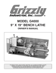
1
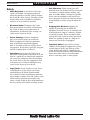
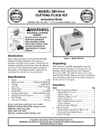
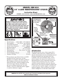
MODEL SB1231
12" 4-JAW INDEPENDENT CHUCK
Instruction Sheet
PHONE: (360) 734-1540 • www.southbendlathe.com
Chucks are heavy! Get assistance when
installing or removing the chuck from the
lathe. Wear heavy duty leather boots for
foot and toe protection, and keep hands and
fingers away from all pinch points. Ignoring
this warning can lead to a severe crushing
injury or finger amputation!
Hardened steel jaws
for durability and
extreme clamping
force and grip
Direct
camlock
spindle
mounting
Independent jaw
screws for each
reversible jaw
Jaw screw
retaining pin
with lock screws
Manufactured
with high-tech
German CNC
machinery
Specifications
•
•
•
•
•
•
•
•
•
•
OD Clamping....... 0.69"–10.04" (17.5–255mm)
ID Clamping........... 3.74"–10.83" (95–275mm)
Chuck Bore Diameter.................2.56" (65mm)
Chuck Outer Diameter...........11.81" (300mm)
Maximum Speed............................2500 RPM*
Mounting Type.......................... D1-8 Camlock
Construction...................Fine-Grain Cast-Iron
Chuck Weight.......................................... 80 lbs
Chuck Shipping Weight.......................... 85 lbs
Country of Origin................................. Taiwan
* The maximum speed listed above is ONLY
possible with the chuck jaws and the
workpiece in complete rotational symmetry.
The workpiece weight must be within the
limits of the lathe, and the workpiece mass
must be of equal density throughout to
prevent centrifugal imbalance or radial
runout—even if a tailstock or other support
is used for additional support.
Fine-grain cast
iron body
Figure 1. Features.
Introduction
The Model SB1231 uses a direct mount D1-8
camlock system where the camlock studs are
directly threaded into to the chuck body instead
of being threaded into a backing plate that
is bolted to the chuck. Without using a back
plate to mount the chuck, the chuck jaws are
positioned closer to the headstock which gives
a longer distance between the jaws and the
tailstock. Another benefit is that the distance
between the jaws and the outboard spindle nose
is reduced, so if a spider support is used on the
outboard spindle, short gun barrels and other
shorter workpieces can be held at both ends.
Copyright © October, 2010 by South Bend Lathe Co.
WARNING: No portion of this manual may be reproduced without written approval.
#CR13310 Printed in Taiwan
Model SB1231
I NSTR UCTIONS
Safety
• Chuck Key Safety: A chuck key left in the
chuck can become a dangerous projectile
when the spindle is started. Always remove
the chuck key after using it. Develop a habit
of not taking your hand off of a chuck key
unless it is away from the machine.
•
Disconnect Power: Disconnect the lathe
from power before installing and removing
the chuck or doing any maintenance or
adjustments. Accidental lathe startup can
cause severe injury or death.
•
Secure Clamping: A thrown workpiece
may cause severe injury or even death.
When swapping the chuck jaw positions,
keep in mind that maximum gripping
force is attained at full jaw and jaw screw
engagement. If only one is partially engaged,
overall clamping force is reduced.
• Speed Rates: Operating the lathe where
maximum chuck speed is exceeded, or at too
high of a speed for an unbalanced workpiece,
can cause the workpiece to be thrown from
the chuck. Always use the appropriate feed
and speed rates. A thrown workpiece may
cause severe injury or even death.
• Large Chucks: Large chucks are very heavy
and difficult to grasp, which can lead to
crushed fingers or hands if mishandled.
Get assistance when installing or removing
large chucks to reduce this risk. Protect your
hands and the precision ground ways by
using a chuck cradle or piece of plywood over
the ways of the lathe when servicing chucks.
-2-
Mfg. Since 5/10
• Safe Clearances: Often chuck jaws will
protrude past the diameter of the chuck and
can contact a coolant nozzle, tooling, tool
post, or saddle. Before starting the spindle,
make sure the workpiece and chuck jaws
have adequate clearance by rotating then by
hand through its entire range of motion by
hand.
• Stopping Lathe By Hand: Stopping the
spindle by putting your hand on the
workpiece or chuck creates an extreme risk
of entanglement, impact, crushing, friction,
or cutting hazards. Never attempt to slow
or stop the lathe chuck by using your hand.
Allow the spindle to come to a stop on its
own or use the brake (if equipped).
•
Long Stock Safety: Long stock can whip
violently if not properly supported, causing
serious impact injury and damage to the
lathe. Reduce this risk by supporting any
stock that extends from the chuck/headstock
more than three times its own diameter.
Always turn long stock at slow speeds.
I NSTR UCTIONS
Mfg. Since 5/10
Model SB1231
Camlock Stud Installation
Camlock Stud Adjustment
The camlock studs that are shipped with this
chuck may be pre-installed from the factory.
If so skip this section and complete Chuck
Installation and Removal on Page 4;
otherwise, install the camlock studs as outlined
below:
If the camlock studs have been pre-installed at
the factory, or if you are installing them for the
first time, slight machining differences between
the lathe spindle and chuck can cause one or
more camlocks to lock at the incorrect location.
1. Oil and thread each cam stud into the chuck
until the alignment groove is flush with the
chuck surface, as shown in Figure 2.
2. Install and tighten the locking cap screw
for each stud, making sure that the camlock
studs can slightly rotate back and forth.
Initial Adjustment:
Camlock Stud
Must Slightly
Rotate Back/Forth
If any cam line stops outside of a “V” mark when
all of the camlocks have been tightened, remove
the chuck and adjust the height of the offending
stud one full turn up or down as illustrated
below. After all camlocks operate correctly,
stamp alignment marks in the chuck and spindle
to ensure that the chuck can be re-installed in
the same position after being removed.
Spindle Line
Camlock Stud Alignment
Groove is Flush with Chuck
Surface
CORRECT
The Camlock Mark
Stops Between the
“V” Marks.
Cap Screw
Installed & Tight
Alignment Marks
INCORRECT
The Camlock Mark
Stops After the
“V” Marks.
INCORRECT
The Camlock Mark
Stops Before the
“V” Marks.
Figure 2. Camlock stud installation.
To Correct:
Turn Stud One Turn In
To Correct:
Turn Stud One Turn Out
Figure 3. Camlock stud adjustment.
-3-
Model SB1231
I NSTR UCTIONS
Mfg. Since 5/10
Chuck Installation and Removal
1. DISCONNECT LATHE FROM POWER!
2. Lay a chuck cradle (see Figure 4) or
plywood under the chuck and over the
bedway to protect the precision ground
surfaces from damage and reduce the risk of
fingers getting pinched.
Do not install the chuck without having
the camlock cap screws in place or fully
tightened. Otherwise, the camlock studs may
turn with the camlocks on release, resulting in
the chuck being permanently locked onto the
spindle.
6. With the help of another person, or with the
help of a chuck cradle, align the chuck with
the spindle so the studs and camlock bores
are aligned correctly, and carefully slide the
chuck onto the lathe spindle. Never rest the
chuck on its lower studs, as shown in Figure
5, and roll or push the top of the chuck into
place on the spindle. This is a bad practice
that may damage the studs and camlock
bores.
Figure 4. Wooden chuck support cradle.
CORRECT
INCORRECT
3. Clean away debris and oily substances from
the mating surfaces of the spindle and the
chuck to ensure the best fit possible.
4. Inspect and make sure that all camlock
studs are undamaged, clean, and lightly
oiled.
5. Make sure that the camlock stud retaining
cap screws are snug, but still allow the studs
to be rotated back and forth slightly by hand.
This free-play is critical to ensure that the
camlocks tighten and lock with the studs
completely, and will release without binding.
—If a problem is found with the camlock
locking or release, remove the offending
stud and clean it with mineral spirits.
Compare it with a good stud for any
inconsistencies, and replace it if a problem
is found. Inspect the bore, cap screw, seat
depth, and threads with others that are
known to be correct. Chase all threads,
and remove any burrs or dings in the seat.
Dry out the bore with compressed air and
lightly re-lubricate with a drop or two of
machine oil or way oil.
-4-
Figure 5. Typical alignment of studs and camlock
bores.
Before turning the lathe
ON, make sure the chuck
key is removed! A thrown
chuck key can cause
serious injury or death to
the operator or bystanders.
Mfg. Since 5/10
I NSTR UCTIONS
7. Tighten camlocks in a star pattern to draw
the chuck in evenly and reduce the chance
of misalignment. Make sure to tighten
camlocks in an incremental manner to
ensure that one camlock does not get fully
tightened before the others (i.e., snug the
camlocks on the first pass, then moderately
tighten on the next pass, then fully tighten
on the third pass).
Model SB1231
To remove the chuck:
1. DISCONNECT LATHE FROM POWER!
2. Lay a chuck cradle or plywood under the
chuck and over the bedway to protect the
precision ground surfaces from damage and
reduce the risk of fingers getting pinched.
As you tighten the camlocks, the chuck
will seat with the spindle nose. When fully
tightened, the cam line will fall between the
two "V" marks on the spindle nose, as shown
in Figure 6.
PINCH HAZARD! Protect your hands and the
precision ground bedways with plywood or a
chuck cradle when removing the lathe chuck!
The heavy weight of a falling chuck can cause
serious injury.
Cam line is between
the "V" marks
Figure 6. Camlock is fully tightened with the camlock
line positioned between the "V" marks.
—If the cam is fully tightened, but the cam
line is positioned outside of the “V” marks,
remove the chuck and adjust the height of
the offending camlock stud, as outlined in
Camlock Stud Adjustment on Page 3.
8. When installation is complete and you are
satisfied with the results, lightly stamp a set
of alignment marks on the chuck and spindle.
3. Loosen the camlocks by turning the key
counterclockwise approximately one-third of
a turn until the mark on the camlock aligns
with the spindle mark on the spindle nose
(see Figure 7). If the stud does not freely
release from the camlock, wiggle the camlock
until it stud releases.
Note: Camlocks can become very tight. A cheater
pipe may be used to add leverage when
loosening.
Cam line is
aligned with the
spindle mark
Note: Alignment marks ensure that the
chuck can be re-installed in the correct
position every time for consistent chuck and
spindle alignment. It also allows for the same
camlocks and studs to operate together for
consistent locking and unlocking.
Figure 7. Camlock is fully loosened when the camlock
line is aligned with the spindle mark.
-5-
Model SB1231
I NSTR UCTIONS
CAUTION: During the next step, the
chuck may come off suddenly, so it
is important that you are ready to
support its weight with a chuck cradle
to prevent crushing your fingers or
dropping the chuck.
4. Using a dead blow hammer or other
soft mallet, lightly tap around the outer
circumference of the chuck body to break the
chuck free from the camlocks and the spindle
nose taper.
Mfg. Since 5/10
6. Following the sequence shown in Figure 8,
tighten each jaw in small increments to move
the workpiece into the required position.
Check frequently to make sure the intended
center point of the workpiece has not
wandered away from the spindle centerline
while the jaws are being tightened.
3
1
Hole to be
bored into
workpiece
5. Use a rocking motion to carefully remove the
chuck from the spindle.
— If the chuck does not immediately come
off, rotate the chuck approximately 60˚
and tap again. Make sure all the marks
on the cams and spindle are in proper
alignment for removal.
Operation
Non-cylindrical parts can be held and brought
into the spindle centerline for facing or boring
The other benefit is that the majority of
workpieces can be positioned out of the spindle
rotation axis if a bore (see Figure 9) or a step
needs to be cut into a workpiece on an outlying
edge. For the best grip possible on odd-shaped
workpieces, one or more jaws can also be rotated
180° to grab more surface area for clamping.
If all four jaws cannot be used to hold the
workpiece, you must use faceplate to reduce the
risk of a workpiece being thrown.
2
4
Figure 8. Tightening sequence.
7. After the workpiece is held in place by
the jaws, turn the chuck by hand and pay
attention to the workpiece alignment.
—If the workpiece is not correctly aligned
for your operation, turn the chuck and
make fine adjustments by slightly
loosening one jaw and tightening the
opposing jaw until the workpiece is
correctly aligned (see Figure 9 for an
example).
To clamp a workpiece in the chuck:
1. DISCONNECT LATHE FROM POWER!
2. Install a center in the tailstock.
3. Retract each jaw and place the workpiece
flat against the chuck face.
4. Slide the tailstock forward, so the tip of the
dead center applies enough pressure against
the workpiece to hold it in place, and then
lock the tailstock in position.
5. Move each jaw until it makes light contact
with the workpiece.
-6-
Figure 9. Non-concentric workpiece correctly clamped
in the 4-jaw chuck.
I NSTR UCTIONS
Mfg. Since 5/10
Model SB1231
Care & Maintenance
!
d
Always disconnect
machine from power before
performing maintenance or
serious personal injury may
result.
a
b
For optimum performance from your chuck,
follow the maintenance schedule below. Never
hammer on the chuck, jaws, or a workpiece that
is clamped in the chuck; and never subject the
chuck to abrasives, flame, or water.
Jaw screw retaining pin
•
•
Check/correct loose mounting bolts.
Keep the chuck clean and oiled.
Use a vacuum, rag, or brush to clean the
chuck after use. Never use air pressure to
clean chips away from a chuck.
Avoid leaving the chuck clamped on a
workpiece, unload the chuck jaws daily.
Make sure the chuck key is removed from
the chuck when not in use.
If the chuck ever becomes stiff to operate,
it may have been contaminated with metal
chips or abrasives from incorrect or infrequent
maintenance intervals. If this is the case, the
chuck must be disassembled, cleaned, and relubricated.
To disassemble the chuck for a full cleaning
and lubrication service:
1. DISCONNECT LATHE FROM POWER!
2. Verify that chuck alignment marks are
present so the chuck can be re-installed in
the same position, and remove the chuck.
Stamp the marks if they do not exist.
3. Leaving the camlock studs in place,
disassemble the chuck in the sequence listed
below and shown in Figure 10.
a. Place a set of wooden blocks under the chuck so the camlock studs do not rest on the table, and clamp the chuck to the table as shown in Figure 10.
d
c
Set screw
Figure 10. Chuck sequence of disassembly.
Daily:
•
•
•
e
b. Back the jaws out of the chuck
c. Remove the four set screws.
d. Put on safety glasses, and use a hammer and drift punch to tap out each jaw screw retaining pin.
e. Slide the jaw screws out of their bores.
4. Using mineral spirits, clean and dry all
parts. Inspect and fix all bores, teeth, pins,
and mating surfaces for wear, burrs, galling,
rust, or cracks.
5. Without changing the dimension of any part,
use a wire brush, emery cloth, or dressing
stones to remove all rust, burrs, or any high
spots caused by galling.
6. Coat all parts with any automotive NLGI #2
grease, and carefully re-assemble the chuck
in the reverse order shown in Figure 10.
7. Rotate the chuck key clockwise until the
lead thread of each jaw screw is seen just
entering the jaw guide, then insert each
numbered jaw into its numbered slot.
8. One at a time, hold each jaw against its jaw
screw, and rotate the chuck key clockwise to
engage the jaw screw with the jaw, then fully
thread the jaw into the chuck.
9. Align and re-install the chuck.
-7-
I NSTR UCTIONS
Model SB1231
Mfg. Since 5/10
Troubleshooting
Symptom
The chuck has
hard spots or binds
completely.
The workpiece slips
in the jaws.
Clamping accuracy
is poor.
Possible Cause
Possible Solution
1. Jaw is in a poor position for
clamping.
1. Re-install jaws for maximum engagement with jaw
slot and jaw screw.
2. Lack of lubrication, rust, burr, or
metal shavings inside of chuck.
2. Disassemble, de-burr, clean, and lubricate chuck.
3. Broken tooth on the jaw or the jaw
screw.
3. Disassemble chuck and repair/replace broken part.
1. Incorrect jaw or workpiece clamping
position.
1. Re-install jaws for maximum engagement with jaw
slot and jaw screw.
2. Chuck is binding before full
clamping force is achieved, or a jaw
or jaw screw is binding.
2. Chuck is loaded up with contaminants. Disassemble
and service chuck. Loosen and retighten the chuck
key several times to distribute lubricant.
3. Cutting overload.
3. Reduce cutting depth or feed rate.
1. Workpiece improperly clamped or
workpiece is misaligned.
1. Remove jaws, clean, de-burr, and re-install; verify
accuracy and recalibrate test/dial indicator.
2. Chuck loose; mounting is off-center,
or is improperly seated.
2. Remove chuck, clean and de-burr mounting; adjust
camlock studs, and re-install chuck.
Parts List
Parts Diagram
REF
PART #
DESCRIPTION
1
2
3
4
5
6
7
8
PSB1231001
PSB1231002
PSB1231003
PSB1231004
PSS02
PSB1231006
PSB1231007
PCAP09
REVERSIBLE CHUCK JAW
CHUCK BODY
JAW SCREW
JAW SCREW PIN
SET SCREW 5/16-18 X 3/8
CHUCK KEY
D1-8 CAMLOCK STUD
CAP SCREW 5/16-18 x 5/8
If you need help with your new chuck,
contact us at:
PHONE: (360) 734-1540
FAX: (360) 676-1075 (International)
FAX: (360) 734-1639 (USA Only)
EMAIL: [email protected]
7
4
8
5
2
1
3
6
Please Note: We included this parts breakdown for service purposes only. Since many of the parts shown are machined to
each individual chuck, they may not be available as replacement items.
-8-