1
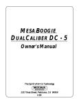
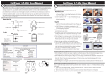
TM
Advanced Tracking Technologies, Inc.
© 2003 ATTI All rights reserved
Copyright © 2003, Advanced Tracking Technologies, Inc.
All rights reserved. No part of this publication may be reproduced or
transmitted in any form or by any means without the prior written
permission of Advanced Tracking Technologies, Inc.
ATTI, Advanced Tracking Technologies, Shadow Tracker, MobilEyes
and Time Traveler are trademarks of Advanced Tracking
Technologies, Inc..
Microsoft, Windows and the Windows logo are registered trademarks
of the Microsoft Corporation.
Pentium is the registered trademark of Intel Corporation.
Other brands and products are trademarks of their prospective
holders.
Federal Communications Commission (FCC) Notice
This equipment has been tested and found to comply
with the limits for a Class A digital device, pursuant to
part 15 of the FCC Rules. These limits are designed to
provide reasonable protection against harmful
interference when the equipment operates in a
commercial environment.
!This equipment generates, uses, and can radiate radio
frequency energy and, if not installed and used in
accordance with the instruction manual, may cause
harmful interference to radio communications.
!Operation of this equipment in a residential area is
likely to cause harmful interference in which case the
user will be required to correct the interference at his
own expense.
!Only peripherals certified to comply with the Class A
limits may be attached to this device. Operation with
non-certified peripherals or peripherals not
recommended by Advanced Tracking Technologies, Inc.
are likely to result in interference to radio and television
reception.
Properly shielded and grounded cables and connectors
must be used in order to meet FCC emission limits.
ADVANCED TRACKING TECHNOLOGIES, INC. is not
responsible for any radio or television interference
caused by using other than recommended cables and
connectors or by unauthorized changes or modifications
to this equipment. Unauthorized changes or
modifications could void the user's authority to operate
the equipment.
TABLE OF CONTENTS
Introduction to MobilEyes™
....................................... 1
Connecting the unit
Getting to know your unit
...................................
3
Connecting the unit to your vehicle
......................
4
Powering the unit
............................................... 5
Downloading the unit
Removing the unit for download
.........................
6
Connecting the unit to your PC
........................... 6
Other Information
......................................................
Safety and Care Instructions
...................................... 8
TC
7
INTRODUCTION
Please read this manual completely before use.
Thank you for purchasing Advanced Tracking Technologies,
Incorporated the Shadow Tracker™ Professional or Shadow
Tracker™ Lite, the cornerstone of the MobilEyes™ vehicle
tracking system. MobilEyes™ is a unique hardware and
software combination, used for the tracking needs of today’s
mobile workforce. Presently, ATTI™ offers three Shadow
Tracker™units for these software packages. They are:
Shadow Tracker™ Jr.
Shadow Tracker™ Pro
Shadow Tracker™ Performer
The Shadow Tracker™ units use a stationary system of
satellites placed around the globe in orbit by the Department
of Defense (DOD). Signals received from one satellite are
compared to signals of three others in view. The small
1
INTRODUCTION
differences in reception can be used to calculate the position
anywhere on the Earth through triangulation.
The Shadow Tracker™ units easily install into vehicles and use
the vehicles electrical system. The Shadow Tracker™
Professional or Shadow Tracker™ Lite software is designed to
handle data from one vehicle at a time. Therefore, anytime
you plan to relocate the Shadow Tracker™ unit in a different
vehicle it should first be cleared of existing data.
The Shadow Tracker™ unit gathers and stores vital GPS data
which is downloaded into the application software providing
detailed distance, location and time information necessary for
accurately monitoring your mobile staff. Data may appear as
if the unit has wandered for short distances and/or brief
periods of time. This may be cused by atmospheric
2
CONNECTING THE UNIT
Getting to know your unit
The POWER connector is located on the side of the Shadow
Tracker™ Pro and Jr. units and in the back of the Shadow
Tracker™ Performer unit. It is used to power the unit both
while in the vehicle and while downloading to the PC. The
DATA connector, also located on the side of the Shadow
Tracker™ Pro and Jr. units and in the back of the Shadow
Tracker™ Performer unit, is only used to connect the unit to
the PC for download. It is not used while in the vehicle.
The ANTENNA connector is located on the rear of the unit and
is connected to the supplied GPS antenna only. DO NOT
connect any GPS antenna other that the one supplied or
damage to the unit and /or antenna will result.
The Shadow Tracker™ Status Indicator LED is located on the
front of the unit. The LED will glow RED when the unit is
powered but is NOT receiving an adequate signal from the
ANTENNA
POWER
DATA
3
CONNECTING THE UNIT
GPS satellites. Once the unit has acquired an adequate signal
the LED will turn GREEN.
Connecting the unit to your vehicle
Mounting the Shadow Tracker™ unit
The Shadow Tracker™ unit is NOT weather proof and must be
mounted inside the vehicles passenger compartment. The
unit must NOT be placed in direct sunlight. The
recommended mounting location is under the dashboard, but
the unit may be mounted anywhere inside the vehicles
passenger compartment out of direct sunlight.
Connecting the Antenna to the unit
Connect the included GPS antenna to the port located on the
rear of the Shadow Tracker™ unit labeled Antenna. Be careful
not to bend the antenna connector when connecting or
disconnecting it from the Shadow Tracker™ unit.
Placing the Antenna
The antenna is attached to the vehicle with the included
magnetic mount. Antenna placement is critical for the best
performance. The antenna requires an unobstructed view of
the sky for accurate satellite acquisition. Recommended
placement for the GPS antenna is on top of the vehicle with a
clear view of the sky. You may choose to mount the antenna
'out of sight'. Keep in mind that the antenna will obtain a
stronger, less disrupted signal if it is mounted under plastic
or glass rather than covered by metal.
Where ever you decide to mount the antenna you must make
4
CONNECTING THE UNIT
sure that the unit is able to acquire an adequate signal from
the satellites. This is indicated by the LED light on the front of
the Shadow Tracker™ unit. The LED will be RED when the unit
is powered on and there is NO signal being received from the
satellites. When there is an adequate signal the LED will turn
GREEN.
Note: Be aware that if the unit has been powered off for 8
hours or
more it may take up to 10 minutes from the time the
antenna is
connected and the unit is powered on
for the unit to acquire an
adequate signal from the
satellites and the LED to turn GREEN. If it takes longer than
15 minutes to acquire a signal then the antenna must
be
moved to a more suitable location. If the LED is not GREEN
then the unit cannot determine the vehicles location or
speed and the
system will not function properly.
Powering the Shadow Tracker™
The POWER connection, located on the side of the unit is used
to power the unit both while in the vehicle and while
downloading to the PC.
The battery on the vehicle serves as the power source for the
Shadow Tracker™ units however, if a unit is left on for an
extended period in which the vehicle is not running the unit
may drain the vehicle battery to the point that the vehicle
cannot be started.
Insert the large end of the DC power cigarette adapter into a
12 volt power port or cigarette lighter socket in your vehicle.
Insert the other end into the Power connector located on the
Shadow Tracker™unit.
5
DOWNLOADING THE UNIT
Note: The unit should only be connected to a '12 volt
center positive'
power port. Damage to the unit will
result if connected to a reversed
polarity or higher voltage
outlet. If you are not certain that your power
outlet is
'12 volt center positive' then do not connect the Shadow
Tracker™ unit at this time. Have the outlet checked by
your local
automotive electronics expert or auto
mechanic.
The Shadow Tracker™ unit must remain connected to a
continuous power supply during vehicle movement for
accurate location readings.
Alternative Power Sources
If your vehicle does not have a cigarette lighter, you can still
use the 12 volt battery in your car as the power source for the
Shadow Tracker™. Consult your local car dealer or other
professional automotive dealer for installation.
Note: If the unit does not successfully power up, refer to
the trouble
shooting section located at the back of this
manual. The unit power
cable should be unplugged when
left for extended periods of time.
Removing the unit for download
Unless you are using the ATTI™ Tracker Extractor or Palm
Extractor utility programs, the Shadow Tracker™ unit must be
removed from your vehicle for the GPS data to be downloaded
into your system. Once the memory is full, the unit will be
unable to continue collecting GPS data until the memory is
cleared. To remove the Shadow Tracker™ unit, disconnect the
Power connector and then the GPS Antenna. Next, remove
6
OTHER INFORMATION
DO NOT connect any other cable or device to the DATA
connector on the Shadow Tracker™ unit as damage will result.
The other end of the PC Download cable connects to a
standard 9-pin serial connection on your PC. If you cannot
locate this connector or need an adapter then you should
Connect Data
cable
Hardwiring the Shadow Tracker Tracking unit
Direct Connect Cable ( ATTI Model Number A-40254 )
The Direct connect cable should be connected into the POWER
connection of the unit. Next, connect the black w/ white
striped wire to a 12 volt positive power source. This wire
must have power even when the vehicle is turned OFF. Then
connect the remaining black wire to a 12 volt ground source.
Shadow Tracker Pro only
Ignition Cable ( ATTI Model Number A-40275 )
To enable ignition switching on your Pro unit, plug the
ignition cable into the ignition connector located on the back
side of the Pro unit. Then connect the red wire into the
vehicles ignition system. To work properly, this connection
must be made at a place where active voltage is on only when
the ignition is on.
7
SAFETY AND CARE
Safety
!
!
!
!
!
!
!
!
!
!
!
!
!
!
Do not place where spills can occur on the unit.
Do not place the unit near a heating device.
Do not place the unit in direct sunlight.
Do not subject the unit to electrical shock.
Do not pour liquid onto the unit.
Do not apply any physical pressure to the unit.
Do not place anything heavy on the unit.
Do not leave any objects on top.
Do not disassemble the unit or any of its components.
Do not scratch, twist, hit or push the surface of the
LED.
Do not use the unit when temperatures are below 40C or above 70C.
Always use the designated AC or DC adapter provided
with the unit to avoid the risk of fire or damage to this
unit.
Do not disassemble the unit or any component of the
product.
Use only power cables or antennas provided by
Advanced Tracking Technologies, Inc.
Caring for the Shadow Tracker™unit
Occasionally the Shadow Tracker™ unit needs to be cleaned.
Use the following precautions.
Cleaning of the Shadow Tracker™ unit:
!
Use a soft cloth to wipe the exterior.
!
Do not use an alkaline detergent.
!
Do not use alcohol on the unit case.
!
Avoid excessive moisture when cleaning the unit.
Care of the antenna:
8
SPECIFICATIONS AND FEATURES
Shadow Tracker™ Jr.
Height:
in.
Width:
Length:
in.
Weight:
Shadow Tracker™ unit
GPS Antenna
DC power cord
Current draw :
@ 12v
Allowable voltage range:
18v DC
Normal operating voltage:
Data download rate:
On board memory:
Operating temperature range:
0.98
2.00 in.
3.38
2.8 oz
2.6 oz.
1.8 oz
120ma
9v to
12v DC
115K Baud
512k
-20 to
Time-To-First-Fix
Satellite
Acquisition
State
Warm
Initialized
Cold
Frozen
Typical
(minutes)
0.03
0.8
2.0
(*)
90%
Probable
(minutes)
Note that times are valid at 25 degrees Celsius with no
satellite signal blockage.(*)= Frozen start is considered t
be a recovery mode. An "out-of-the-box" board that has
not operated for a significant amount of time (months)
may approximate this state because the data in EEPROM
may be valid but expired or partially complete.
0.4
1.0
2.5
(*)
9
SPECIFICATIONS AND FEATURES
Shadow Tracker™ Pro
Height:
in.
Width:
Length:
in.
Weight:
Shadow Tracker™ unit
GPS Antenna
DC power cord
Current draw :
@ 12v
Allowable voltage range:
18v DC
Normal operating voltage:
Data download rate:
On board memory:
Operating temperature range:
70 C
Approximate data storage time:
0.98
2.00 in.
3.38
2.8 oz
2.6 oz.
1.8 oz
120ma
9v to
12v DC
115K Baud
2 MB
-40 to
1200
Time-To-First-Fix
Satellite
Acquisition
State
Warm
Initialized
Cold
Frozen
Typical
(minutes)
0.03
0.8
2.0
(*)
90%
Probable
(minutes)
Note that times are valid at 25 degrees Celsius with no
satellite signal blockage.(*)= Frozen start is considered t
be a recovery mode. An "out-of-the-box" board that has
not operated for a significant amount of time (months)
may approximate this state because the data in EEPROM
may be valid but expired or partially complete.
0.4
1.0
2.5
(*)
10
SPECIFICATIONS AND FEATURES
Shadow Tracker™ Performer
Height:
in.
Width:
Length:
in.
Weight:
Shadow Tracker™ unit
GPS Antenna
DC power cord
Current draw :
100ma @ 12v
Allowable voltage range:
18v DC
Normal operating voltage:
Data download rate:
On board memory:
Operating temperature range:
70 C
Approximate data storage time:
Hrs.
1.15
3.4 in.
6.1
2.8 oz
2.6 oz.
1.8 oz
9v to
12v DC
115K Baud
1 MB
-40 to
600
Time-To-First-Fix
Satellite
Acquisition
State
Warm
Initialized
Cold
Frozen
Typical
(minutes)
0.03
0.8
2.0
(*)
90%
Probable
(minutes)
Note that times are valid at 25 degrees Celsius with no
satellite signal blockage.(*)= Frozen start is considered t
be a recovery mode. An "out-of-the-box" board that has
not operated for a significant amount of time (months)
may approximate this state because the data in EEPROM
may be valid but expired or partially complete.
0.4
1.0
2.5
(*)
11
TROUBLESHOOTING
Problem
Action
Unit LED does not
light Red or Green.
!Make sure the plug is
properly connected to
the back of the unit.
!Make sure the plug is
properly connected into
the cigarette lighter in
the vehicle.
!Check the fuse for the
cigarette lighter in your
vehicle.
!Check fuse in the end of
the DC power cord.
Status indicator
LED will not
turn green. Unit
does not
receive signal.
!Check antenna
connection.
!Make sure the antenna
cable is not crimped or
cut.
!Reposition the antenna.
12
Hardware Manual
Manual Number: M-21710
Revison: 2/20/2003
TM
Advanced Tracking Technologies Inc.
P.O.Box 168
Sugar Land, Texas 77487
Tel: (713) 353-6065
Fax: (713) 353-6050