1
A-A0R-107-11(1)
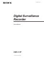
Digital Surveillance
Recorder
Protocol Manual
HSR-1/1P
1999 by Sony Corporation
Purpose of This Manual
This manual describes the procedure for controling the HSR-1/1P Digital
Surveillance Recorder using the RS-232C from an external computer, etc.
The RS-232C is the EIA standard for the interface of the communication via a
modem between data terminal equipment. In this interface, data are transferred
serially bit by bit. Since the RS-232C interface is employed in most computers
as a standard interface, it can be used in a wide range of applications.
Table of Contents
Overview ............................................................................................... 3
Signal Connections ........................................................................................ 3
Data Format ................................................................................................... 3
Command Table............................................................................................. 3
Communication Protocol .................................................................... 4
Detailed Descriptions of Commands ................................................. 5
VTR Return Commands ................................................................................ 5
Numerical Value Commands ......................................................................... 5
General Purpose Control Commands ............................................................ 6
Mode Control Commands.............................................................................. 6
Status Request Commands .......................................................................... 10
Tape Run System Commands ...................................................................... 16
Menu ITEM Numbers and Set Values......................................................... 18
2
Overview
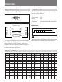
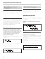
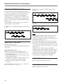
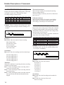
Signal Connections
Data Format
The signals used in the HSR-1/1P are shown below.
The data format is preset as shown below. Only the
baud rate can be changed.
Mode:
Data Length:
Parity:
Stop Bit:
Baud Rate:
PC
VTR
Connection cable
1
2
3
4
5
6
7
8
9
DCD
RxD
TxD
DTR
GND
DSR
RTS
CTS
RI
1
2
3
4
5
6
7
8
9
RS-232C interface
Asynchronous
8 bits
None
1 bit
1200/2400/4800/9600/19200/38400
bps
Bit Structure
RxD
TxD
DTR
GND
DSR
RTS
CTS
START
BIT
D0
D1
D2
D3
D4
D5
D6
D7
STOP
BIT
Note
This interface may not operate at 19200 or 38400 bps,
depending upon the specifications of the computer and
characteristics of the cable. Select a lower baud rate.
Use a cross-wire (flipped) cable to connect a computer
to the HSR-1/1P. The RTS and CTS are not controlled
and are shorted in a VTR. Therefore, either set the
computer so as not to control the RTS/CTS signals or
connect wires between the pin 7 and pin 8 as shown by
the broken lines in the figure above.
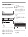
Command Table
0
1
2
0
3
4
0
ENTER
C.E.
1
COMPLETION
1
2
ERROR
2
3
CASSETTE
OUT
3
4
5
6
7
8
9.1
9.3
SCREEN
DEVIDE
SCREEN
AUTO
CHANGE
CAMERA
SELECT
VERSION
INQ
LOCK ON
5
LOCK OFF RESERVED
6
ALARM IN
6
7
ALARM
SEARCH
8
8
REC
MODE
9
9
REC
PRESET
A
ACK
EJECT
PLAY
/A
ALARM
PRESET
B
NAK
FWD STEP
AND STILL
B
TIMER
PRESET
REV STEP
AND STILL
C
E
STOP
/F
D
E
F
+
CAMERA
SENSE
–
T/D
SENSE
ALARM
SENSE
FRAME
SENSE
FWD
SHUTTLE
REV
SHUTTLE
REC
F.FWD
HEAD
HOURS
OPERATION
HOURS
ALARM
LIST
SENSE
REC
MODE
SENSE
REC
PRESET
SENSE
ALARM
PRESET
SENSE
TIMER
PRESET
SENSE
EXP-1
EXP-3
REC
REQUEST
VCR INQ
REW
D
F
C.3
STATUS
SENSE
T/D
SEARCH
C.L.
7
E
C
ALARM
SET
4
NOT
TARGET
D
B
T/D
PRESET
5
C
A
DEVICE
TYPE
REQUEST
USER
DATA
PRESET
MENU
PRESET
USER
DATA
SENSE
MENU
SENSE
RESERVED
RESERVED
3
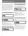
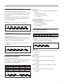
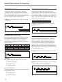
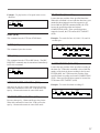
Communication Protocol
Communication is carried out in units of bytes in the
following procedure. When the computer sends one
byte of data, it waits for a return from the VTR before
sending the next byte. The return from the VTR may
not only be one byte of data, but can be multiple bytes
of data. For a command, such as EJECT, which takes
time to execute, not only the return immediately after
receipt of the command is issued, but a return
indicating the result of execution upon completion of
operation is also issued. The command, the return
from the VTR, and parameters are all defined as the
command in the RS-232C protocol.
Commands to operate the VTR
When a command (CMD) has no parameter:
RxD
TxD
CMD
3AH
0AH
RET
When a command (CMD) has parameters (PARAM.):
RxD
TxD
CMD
3AH
PARAM.
PARAM.
3AH
3AH
0AH
0AH
0AH
RET
RET
RET
There are three kinds of returns from the VTR: ACK,
NAK, and ERROR.
ACK: Returned when data is correctly returned.
NAK: Returned when communication error is
detected or an unidentified command is received.
ERROR: Returned when a command cannot be
executed because of tape slack and other errors.
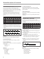
Commands to sense VTR status
RxD
TxD
4
EXP-3
DAH
CMD
C7H
0AH
ACK
xxH xxH xxH xxH
DATA DATA DATA DATA
Commands from the VTR to the computer
to notify of completion of an operation
This return is issued when execution of the following
commands is completed: EJECT, FRAME SEARCH,
T/D SEARCH, and ALARM SEARCH.
RxD
TxD
CMD
2AH
0AH
RET
03H
CASSETTE
OUT
There are three kinds of return from the VTR:
COMPLETION, NOT TARGET, and CASSETTE
OUT.
COMPLETION: Returned when command
execution is correctly completed.
NOT TARGET: Returned when the target point
specified by the command cannot be found.
CASSETTE OUT: Returned when the cassette is
ejected.
Extended commands
A command consists basically of one byte. Some
commands may function when combined with another
command.
RxD
TxD
Extended Secondary
CMD
CMD
DAH
CAH
0AH
31H
RET
RET
Notes
• Do not send the next command before receiving the
return from the VTR.
If the return from the VTR is not received within 10
msec or more after the transmission is completed,
appropriate processing must be executed because the
communication is judged not executed correctly.
• Do not send any other command between the
extended command and the secondary command.
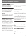
Detailed Descriptions of Commands
VTR Return Commands
When the VTR receives a command from the
computer, it returns a VTR return command. The
HSR-1/1P supports the following commands.
ACK (0AH)
ACK is returned when the VTR receives the defined
command correctly. When the command from
computer requests STATUS SENSE or other data,
ACK is not returned, but only data is returned.
NAK (0BH)
NAK is returned if a command which is not defined
for the current mode (for example, a numerical value
command in a mode other than the numerical input
mode) is received, or when a communication error is
detected.
COMPLETION (01H)
COMPLETION is returned when the VTR has
completed the operation of the T/D SEARCH or
ALARM SEARCH command. The COMPLETION
command will not be returned if the VTR receives a
tape-run-related command or the C.L. command
before completion of the above commands, because
the VTR stops executing the above commands to
execute a new command.
ERROR (02H)
Notifies of generation of an error during operation.
ERROR is returned when a VTR receives a command
that cannot be executed because of an error, such as
tape slack, etc., or when an error has occurred during
execution of the T/D SEARCH or ALARM SEARCH
command, and stopped the operation. Remove the
cause of the error and release the error status using the
C.E. and C.L. commands.
NOT TARGET (05H)
Notifies that the VTR could not find the specified
position on the tape when executing the T/D SEARCH
or ALARM SEARCH command.
CASSETTE OUT (03H)
Notifies that the cassette was ejected.
ALARM IN (06H)
Notifies of alarm input. Each time an alarm is
generated, this command is issued. Which channel is
in alarm status can be confirmed by using the ALARM
SENSE (DAH+C4H) command.
Numerical Value Commands
The numerical value commands are used to specify
numerical parameters. These commands are also used
when returning numerical data, such as time data, from
the VTR to the computer. The following four
command formats are supported:
Numerical value commands 0 to 9 (30H to
39H)
To express numerical values 0 to 9 for each command.
Numerical value commands A to F (3AH to
3FH)
To express numerical values A to F for each command.
Sign (+) command (A1H) and sign (–)
command (A2H)
Used to specify the sign of numerical data.
ENTER (40H)
Used to specify completion of numerical parameter
input.
5
Detailed Descriptions of Commands
General Purpose Control
Commands
Mode Control Commands
REC REQUEST (FAH)
C.E. (41H)
This clears the error status or the last character of
numerical data entered. A sign entered cannot be
cleared with this command. To clear a sign, enter the
new sign.
C.L. (56H)
This releases the error status and clears the present
command. If the C.L. command is sent after issuing a
command with numerical parameter but before
confirming the numerical parameter, the numerical
parameter input is stopped, and the command with
numerical value parameter is cleared.
This command must be issued immediately before
sending the REC command.
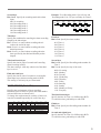
SCREEN DIVIDE (DAH+90H)
Selects the display structure.
Two bytes for the number of divisions, another 2 bytes
for the page number, and the ENTER command (40H)
must follow.
Example: To select the second page of 4-division
mode:
RxD
TxD
EXP-3
DAH
CMD
90H
0AH
ACK
0
30H
0AH
ACK
Example: When the LOCK ON command is correctly
executed.
RxD
TxD
EXP-1
D8H
CMD
94H
0AH
ACK
0AH
ACK
Example: This is a case in which the LOCK ON
command could not be correctly executed because a
command other than a secondary command was
issued after the extended command:
RxD
TxD
6
EXP-1
D8H
other CMD
CMD
72H
94H
0AH
0BH
0BH
ACK
NAK
NAK
0AH
ACK
0
30H
EXP-1 (D8H), EXP-3 (DAH)
EXP-1 and EXP-3 are the first and third extended
commands. These commands become valid after they
are combined with a secondary command. If any other
command is issued between this command and the
secondary command, the extended command is
canceled, and NAK is returned.
4
34H
0AH
ACK
2
32H
0AH
ACK
ENTER
40H
0AH
ACK
0AH
ACK
SCREEN AUTO CHANGE (DAH+91H)
Automatically switches the display.
Parameter bytes to specify the output port (A or B) and
the cycle in seconds and the ENTER command (40H)
must follow.
If 00 is specified for the cycle, no automatic switching
is executed.
If the output port is not specified, output port A is
selected.
Example: To switch the display for output port A
every 5 seconds:
RxD
TxD
EXP-3
DAH
CMD
91H
0AH
ACK
A
3AH
0AH
ACK
5
35H
0AH
ACK
ENTER
40H
0AH
ACK
0AH
ACK
CAMERA SELECT (DAH+92H)
Directly selects the camera to be monitored.
Parameter bytes to specify the output port (A or B) and
the camera number and the ENTER command (40H)
must follow.
By setting the camera number to A (3AH) for output
port B, the same signal as that from port A can be
output from both ports.
Example: To select camera 16 for output port B:
RxD
TxD
EXP-3
DAH
CMD
92H
0AH
ACK
B
3BH
0AH
ACK
1
31H
0AH
ACK
6
36H
0AH
ACK
ENTER
40H
0AH
ACK
First byte
Bits 1 and 0: Specify the alarm input common to all
cameras.
00: Cancel alarm input
01: Specify the alarm input
11: No change
Second to fifth bytes
Each two bits specifies the alarm input of the
corresponding camera.
00: Cancel alarm input
01: Specify the alarm input
11: No change
0AH
ACK
REC MODE (DAH+98H)
Specifies the Recording mode.
T/D PRESET (DAH+93H)
Sets the built-in clock.
Parameter bytes to specify the year, month, day, hour
(24H mode), minute and second in this sequence and
the ENTER command (40H) must follow.
Example: To set January 1, 1998, 3:10, and 58
seconds p.m.:
RxD
TxD
EXP-3
DAH
CMD
93H
0AH
ACK
9
39H
0AH
ACK
8
38H
0AH
ACK
0
30H
Sets the VTR to Alarm mode.
Parameter bytes to control the alarm may follow. The
parameters are of the same format as those of the
return data for ALARM SENSE.
bit 7
bit 6
bit 5
bit 4
bit 3
bit 2
1
0
0
0
0
0
bit 1
bit 0
ALL CAMERAS
byte 2
CAMERA4
CAMERA3
CAMERA2
byte 3
CAMERA8
CAMERA7
CAMERA6
CAMERA5
byte 4
CAMERA12
CAMERA11
CAMERA10
CAMERA9
byte 5
CAMERA16
CAMERA15
CAMERA14
CAMERA13
RxD
TxD
EXP-3
DAH
CMD
94H
0AH
ACK
DATA
80H
0AH
ACK
DATA
xxH
CAMERA1
DATA
xxH
0AH
ACK
bit 5
bit 4
bit 3
0
0
0
0
byte 2
0
TIMER
REC
REPEAT CONTINUREC
OUS REC
0
bit 2
bit 1
bit 0
NORMAL REC MODE
ALARM
REC
0
0
Example: To specify Recording mode 1 for normal
recording and activate Repeat recording:
EXP-3
DAH
CMD
98H
0AH
ACK
CMD
81H
0AH
ACK
CMD
20H
0AH
ACK
0AH
ACK
First byte
Bits 2 to 0: Specify the recording mode for normal
recording.
0AH
ACK
ALARM SET (DAH+94H)
byte 1
bit 6
1
RxD
TxD
ENTER
40H
0AH
ACK
bit 7
byte 1
Second byte
Bit 6: Activates/deactivates Timer recording.
0: Inactive
1: Active
Bit 5: Activates/deactivates Repeat recording.
0: Inactive
1: Active
Bit 4: Activates/deactivates Continuous recording.
0: Inactive
1: Active
Bit 2: Activates/deactivates Alarm recording.
0: Inactive
1: Active
DATA
xxH
0AH
ACK
0AH
ACK
7
Detailed Descriptions of Commands
REC PRESET (DAH+99H)
Sets the requirements for the Recording modes.
Parameter bytes to follow to specify the requirements
are the same format of those of the return data for REC
PRESET SENSE (DAH+C9H).
The time mode and recording cycle cannot be set in
combination. If both are specified, the time mode
setting has priority, and the recording cycle setting is
ignored.
byte 1
bit 7
bit 6
bit 5
bit 4
bit 3
1
0
0
0
0
bit 2
bit 1
bit 0
CAMERA8 CAMERA7 CAMERA6 CAMERA5 CAMERA4 CAMERA3 CAMERA2 CAMERA1
byte 3
CAMERA
16
byte 5
byte 6
CAMERA
15
CAMERA
14
CAMERA
13
CAMERA
12
Thousands of TAPE LENGTH
0
CAMERA
11
CAMERA CAMERA9
10
Hundreds of TAPE LENGTH
Tens of TAPE LENGTH
0
Units of TAPE LENGTH
0
0
0
QUALITY MODE
byte 7
Thousands of TIME MODE
byte 8
Tens of TIME MODE
Units of TIME MODE
byte 9
Tens of REC CYCLE
Units of REC CYCLE
byte 10
Ninth and tenth bytes
Specify the recording cycle in units of 0.01 second by
a BCD code.
When the cycle is not to be specified, pad both bytes
with FFH.
REC MODE
byte 2
byte 4
Seventh and eighth bytes
Specify the time mode in units of hours in BCD.
When the time mode is not to be specified, pad both
bytes with FFH.
Hundreds of TIME MODE
ALARM PRESET (0AH+9AH)
Specifies the requirements for alarm recording.
The parameters to be set depend on the mode of alarm
recording.
Down to the 1st decimal place of REC CYCLE Down to the 2nd decimal place of REC CYCLE
byte 1
Example: To set the number of cameras to 16, the
tape length to 270 minutes, the image quality mode to
HIGH and the time mode to 123 hours for Recording
mode 1:
RxD
TxD
EXP-3
DAH
CMD
99H
0AH
ACK
DATA
70H
DATA
01H
0AH
ACK
DATA
02H
0AH
ACK
DATA
FFH
0AH
ACK
DATA
01H
0AH
ACK
DATA
FFH
0AH
ACK
DATA
23H
0AH
ACK
DATA
02H
0AH
ACK
DATA
FFH
0AH
ACK
0AH
ACK
DATA
FFH
0AH
ACK
0AH
ACK
First byte
Bits 2 to 0: Specify the Recording mode number.
Second and third bytes
Specify the tape length in units of minutes in BCD.
Fourth and fifth bytes
Each bit specifies whether to record the corresponding
camera input.
0: Not to record
1: Record
Sixth byte
Specifies the image quality mode.
001: SUPER
010: HIGH
011: MID
100: LOW
111: No change
8
bit 7
bit 6
bit 5
bit 4
bit 3
1
0
0
0
0
0
bit 2
bit 1
byte 2
0
0
0
0
byte 3
TAPE END
ALARM
OFF
0
TIME
Hundreds of ALARM OFF TIME
0
Hundreds of PREALARM TIME
byte 4
byte 5
Tens of ALARM OFF TIME
0
byte 6
0
0
Tens of PREALARM TIME
bit 0
ALARM MODE
REC MODE (After Alarm)
Units of ALARM OFF TIME
Units of PREALARM TIME
Normal mode: The pre-alarm time setting (bytes 5
and 6) is ignored.
Interleave mode: The pre-alarm time setting (bytes 5
and 6) is ignored.
Event mode: The pre-alarm time setting (bytes 5 and
6) is ignored.
Frame mode: The settings of the condition for
canceling the alarm recording (bytes 2 and 3) and
the pre-alarm time (bytes 5 and 6) are ignored.
Example: To switch to Recording mode 2 upon an
alarm input and return to normal recording in 30
seconds:
RxD
TxD
EXP-3
DAH
CMD
9AH
0AH
ACK
80H 02H 10H 30H 00H 00H
DATA DATA DATA DATA DATA DATA
First byte
Bits 2 to 0: Specify the mode for alarm recording.
000: Normal mode.
001: Interleave mode
010: Event mode
011: Pre-alarm mode
100: Frame mode
Second byte
Bits 2 to 0: Specify the recording mode after alarm
input.
000: No recording
001: Recording mode 1
010: Recording mode 2
011: Recording mode 3
100: Recording mode 4
101: Recording mode 5
Example: To set Recording mode 1 for 8:00 a.m. and
Recording mode 2 for 5:30 p.m. on Friday for Timer 5:
Third byte
Specify the condition for canceling the alarm recording
started by the alarm input.
Bit 7: Set to 1 to cancel alarm recording when it
reaches the end of the tape.
Bit 6: Set to 1 to cancel alarm recording when the
alarm input stops.
Bit 4: Set to 1 to cancel alarm recording when the
time specified by the third and fourth bytes has
elapsed.
First byte
Bits 2 to 0: Specify the timer number.
Third and fourth bytes
Specify the time in units of seconds until canceling
alarm recording in BCD.
This time setting is valid only when bit 4 of the third
byte is set to 1.
Second byte
Bits 2 to 0: Specify the Recording mode number for
Time 1.
Bits 7 to 4: Specify the day of the week.
Fifth and sixth bytes
Specify the time in units of seconds to record before
alarm input in pre-alarm recording mode in BCD.
This setting is valid only for pre-alarm mode.
TIMER PRESET (DAH+9BH)
Specifies the requirements of timer recording.
Parameter bytes to follow to specify the timer number
code and the items are shown below
To change the requirements for each day of the week,
issue this command repeatedly for each of the days.
byte 1
bit 7
bit 6
bit 5
bit 4
bit 3
1
0
0
0
0
TIMER PRESET NUMBER
0
REC MODE (TIME 1)
byte 2
WEEK
bit 2
bit 1
by te 3
Tens of HOURS (TIME 1)
Units of HOURS (TIME 1)
byte 4
Tens of MINUTES (TIME 1)
Units of MINUTES (TIME 1)
by te 5
0
0
0
0
0
RxD
TxD
EXP-3
DAH
CMD
9BH
0AH
ACK
DATA
05H
0AH
ACK
DATA
51H
0AH
ACK
DATA
80H
0AH
ACK
DATA
02H
DATA
00H
0AH
ACK
DATA
17H
0AH
ACK
0AH
ACK
DATA
30H
0AH
ACK
0AH
ACK
001: Timer 1
010: Timer 2
011: Timer 3
100: Timer 4
101: Timer 5
110: Timer 6
111: Timer 7
0000: No setting
0001: Monday
0010: Tuesday
0011: Wednesday
0100: Thursday
0101: Friday
0110: Saturday
0111: Sunday
1001: Monday to Friday
1111: Everyday
Third and fourth bytes
Specify the time for Time 1 in 24H mode in BCD.
To cancel the time, pad both bytes with FFH.
bit 0
Fifth byte
Bits 2 to 0: Specify the Recording mode number for
Time 2.
REC MODE (TIME 2)
byte 6
Tens of HOURS (TIME 2)
Units of HOURS (TIME 2)
byte 7
Tens of MINUTES (TIME 2)
Units of MINUTES (TIME 2)
Seventh and eighth bytes
Specify the time for Time 2 in 24H mode in BCD.
To cancel the time, pad both bytes with FFH.
9
Detailed Descriptions of Commands
USER DATA PRESET (DAH+9EH)
Sets user data to be added to each picture frame to be
recorded. A maimum of 32 bytes (NTSC model) or 40
bytes (PAL model) can be recorded/reproduced. If
data of less than 32 or 40 bytes are specified, the
remaining bytes are padded with 0s. If data of more
than 32 or 40 bytes are specified, the extra bytes are
ignored. Use the numerical value commands (30H to
3FH) for data.
The user data are valid for pictures to be recorded
(captured) after you set the data.
Example: To set user data 01H and so on for camera
10:
RxD
TxD
EXP-3
DAH
CMD
92H
0AH
ACK
1
31H
0AH
ACK
DATA
30H
DATA
31H
0AH
ACK
RxD
TxD
EXP-3
DAH
CMD
9EH
0AH
ACK
SUBCMD
2
3
ENTER
00H
32H
33H
40H
0AH
0AH
0AH
0AH
0AH
ACK
ACK
ACK
ACK
ACK
1
31H
0AH
ACK
ENTER
40H
0AH
ACK
0AH
ACK
Example 2: To write the data to nonvolatile memory:
RxD
TxD
EXP-3
DAH
CMD
9EH
0AH
ACK
SUBCMD
F0H
0AH
0AH
ACK
ACK
01H
COMPLETION
0AH
ACK
Notes
ENTER
40H
0AH
ACK
0AH
ACK
MENU PRESET (DAH+9EH)
Specifies the setup menus.
The operation is determiend by the subcommand (first
byte) value.
Subcommand (first byte)
00H: Sets data for the specified ITEM number.
10H: Reads the data of all the ITEM numbers from
nonvolatile memory
20H: Returns the data of all the ITEM numbers to the
factory default settings.
21H: Returns all the data except those related to the
parallel I/O to the factory default settings.
F0H: Stores the current settings to nonvolatile
memory.
For the ITEM numbers and data values, see “Menu ITEM
Numbers and Set Values” on page 18.
• When the subcommand is 10H, 20H, 21H, or F0H,
COMPLETION (01H) will be returned after the
respective operation is completed. Menu operation is
disabled during this process.
• To maintain any change in data, be sure to store the
data in nonvolatile memory (the subcommand F0H).
If the data are not written to nonvolatile memory, the
previous settings will be resumed when you next turn
on the power.
• When the menu version changes, some ITEM
numbers may be added or deleted. Similarly, data of
an ITEM number may be added, while the meaning
of data items of the same number does not change.
• When a menu is being operated on the HSR-1/1P,
menu operation via the RS-232C is disabled.
LOCK ON (D8H+94H)
Disables all function keys of the VTR.
LOCK OFF (D8H+95H)
Enables all function keys of VTR.
10
2
32H
ENTER
40H
0
30H
0AH
ACK
Example 1: To change the ITEM number 23 data
setting to 12:
Status Request Commands
DEVICE TYPE REQUEST (8FH)
Requests the information on the type of equipment
controlled. The device type is a unique code assigned
to each model to distinguish it from other models. The
device type of the HSR-1/1P is A0H.
Example: With HSR-1/1P:
RxD
TxD
CMD
8FH
A0H
DEVICE TYPE
STATUS SENSE (DAH+C0H)
Requests the return of VTR status data. When this
command is issued, the VTR returns four-byte status
data, as shown below.
bit 7
bit 6
bit 5
bit 4
bit 3
bit 2
bit 1
bit 0
byte 1
1
0
0
REC
INHIBIT
CASSETTE
OUT
ALARM
0
ERROR
byte 2
PAUSE
0
SEARCH
PLAY
REW
F.FWD
STOP
EJECT
byte 3
0
TIMER
REC
REPEAT
REC
CONTINUOUS REC
byte 4
FWD/REV
0
0
0
T/D
SEARCH
RESERVED
RxD
TxD
EXP-3
DAH
ALARM REC
0
ALARM
SEARCH
Fourth byte
bit 7: Shows the search direction when the VTR is in
Search mode.
0: FWD
1: REV
bit 2: Becomes 1 while the VTR is executing the
ALARM SEARCH (DAH+97H) command.
bit 1: Becomes 1 while the VTR is executing the T/D
SEARCH (DAH+96H) command.
bit 0: Reserved
REC
CMD
C7H
0AH
ACK
Third byte
bit 6:
0: No timer setting
1: Timer On
bit 5: Becomes 1 when Repeat recording is on.
bit 4: Becomes 1 when Continuous recording is on.
bits 3, 2 and 1:
000: No alarm recording setting
001: Alarm recording in Normal mode is on.
010: Alarm recording in Interleave mode is on.
011: Alarm recording in Event mode is on.
100: Alarm recording in Pre-alarm mode is on.
101: Alarm recording in Frame mode is on.
bit 0: Becomes 1 when the VTR is recording.
xxH xxH xxH xxH
DATA DATA DATA DATA
CAMERA SENSE (DAH+C2H)
Requests the status of camera connections and video
signal inputs. When this command is issued, the VTR
returns the five-byte status data shown below.
byte 1
First byte
bit 4: Becomes 1 when a record inhibited tape is
inserted.
bit 3: Becomes 1 when a cassette is not loaded into
the VTR.
bit 2: Becomes 1 when an alarm occurs is generated.
bit 0: Becomes 1 when an error occurs.
Second byte
bit 7: Becomes 1 when the VTR is in Pause mode.
bit 5: Becomes 1 when the VTR is in Search mode.
bit 4: Becomes 1 when the VTR is in Play mode.
bit 3: Becomes 1 when the VTR is in Rewind mode.
bit 2: Becomes 1 when the VTR is in Fast forward
mode.
bit 1: Becomes 1 when the VTR is in Stop mode.
bit 0: Becomes 1 while the VTR is ejecting the
cassette.
byte 2
bit 7
bit 6
bit 5
bit 4
bit 3
bit 2
bit 1
bit 0
1
0
0
0
0
0
0
0
CAMERA4
CAMERA3
CAMERA2
CAMERA1
CAMERA5
byte 3
CAMERA8
CAMERA7
CAMERA6
byte 4
CAMERA12
CAMERA11
CAMERA10
CAMERA9
byte 5
CAMERA16
CAMERA15
CAMERA14
CAMERA13
RxD
TxD
EXP-3
DAH
CMD
C2H
0AH
ACK
80H xxH xxH xxH xxH
DATA DATA DATA DATA DATA
Second to fifth bytes
Each two bits show the status of the corresponding
camera.
00: NO CONNECT
10: No signal input
11: Signal being input
11
Detailed Descriptions of Commands
T/D SENSE (DAH+C3H)
FRAME SENSE (DAH+C5H)
Requests the date/time of recording. When this
command is issued, the VTR returns the date/time
(year/month/day/hour/minute/second in sequence) of
the current playback picture in playback mode or the
current date/time in other operation modes.
Requests the position on the tape of the current
playback picture. When this command is issued, the
VTR returns the time code data of the current playback
picture and the subdata to indicate the area within the
frame. The value of the subdata depends on the image
quality mode, as shown below.
Example: In the case of Jan. 31, 1988, 3:10 and 58
seconds p.m.:
HYPER
SUPER
HIGH
MIDDLE
LOW
0
0 to 1
0 to 3
0 to 7
0 to 15
Subdata value
Example: If the time code is 01:23:45:12 and the
subdata value is 3:
EXP-3
CMD
RxD DAH
C3H
TxD
0AH
39H 38H 30H 31H 33H 31H
ACK
9
8
0
1
3
1
31H 35H 31H 30H 35H 38H
5
1
0
5
8
1
RxD
TxD
EXP-3
DAH
CMD
C5H
0AH
ACK
30H 31H 32H 33H 34H 35H 31H 32H 30H 33H
0
1
2
3
4
5
1
2
0
3
ALARM SENSE (DAH+C4H)
Requests the channel of the generated alarm. When
this command is issued, the VTR returns the data
shown below. Each flag is set when an alarm is
generated and reset when the condition to cancel the
alarm is satisfied.
byte 1
bit 7
bit 6
bit 5
bit 4
bit 3
bit 2
1
0
0
0
0
0
bit 1
bit 0
ALL CAMERAS
byte 2
CAMERA4
CAMERA3
CAMERA2
byt e 3
CAMERA8
CAMERA7
CAMERA6
CAMERA1
CAMERA5
byt e 4
CAMERA12
CAMERA11
CAMERA10
CAMERA9
byte 5
CAMERA16
CAMERA15
CAMERA14
CAMERA13
ALARM LIST SENSE (DAH+C7H)
Requests information on the alarm list. When this
command is issued with the number of the desired
alarm recording on the list and ENTER (40H), the
VTR returns the information (year/month/day/hour/
minute/second in sequence) of the specified alarm
recording. When 0 is specified for the alarm recording
number, the number of the alarm recordings on the list
is returned by three bytes.
Example: When 85 alarm recordings are on the list:
RxD
TxD
EXP-3
DAH
CMD
C4H
0AH
ACK
80H xxH xxH xxH xxH
DATA DATA DATA DATA DATA
First byte
Bits 1 and 0: Show the status of the alarm input
common to all cameras.
00: No alarm input
01: Alarm generated
Second to fifth bytes
Each two bits show the status of the alarm input of the
corresponding camera.
00: No alarm input
01: Alarm generated
12
RxD
TxD
EXP-3
DAH
CMD
C7H
0AH
ACK
0
30H
0AH
ACK
ENTER
40H
0AH
ACK
30H 38H 35H
0
8
5
Example: When alarm recording 37 was recorded on
Jan. 31, 1998, 3:10 and 58 seconds, p.m.:
RxD
TxD
EXP-3
DAH
CMD
C7H
0AH
ACK
3
33H
0AH
ACK
7
37H
0AH
ACK
ENTER
40H
0AH
ACK
39H 38H 30H 31H 33H 31H 31H 35H 31H 30H 35H 38H
5
1
0
5
8
9
8
0
1
3
1
1
Example: In the case of Recording mode 1, 16
cameras, 270-minute tape, HIGH image quality
mode, 123-hour time mode, 1.8-second cycle:
REC MODE SENSE (DAH+C8H)
Requests the specified recording mode.
bit 7
bit 6
bit 5
bit 4
bit 3
byte 1
1
0
0
0
0
byte 2
0
TIMER
REC
REPEAT CONTINUREC
OUS REC
bit 2
bit 1
bit 0
NORMAL REC MODE
ALARM
REC
0
0
0
RxD
TxD
Example: When Recording mode 1 is set for normal
recording and Repeat recording is active:
RxD
TxD
EXP-3
DAH
CMD
C8H
0AH
ACK
Second byte
Bit 6: Shows the status of Timer recording.
0: Inactive
1: Active
Bit 5: Shows the status of Repeat recording.
0: Inactive
1: Active
Bit 4: Shows the status of Continuous recording.
0: Inactive
1: Active
Bit 2: Shows the status of Alarm recording.
0: Inactive
1: Active
bit 7
bit 6
bit 5
bit 4
bit 3
1
0
0
0
0
bit 2
bit 1
bit 0
REC MODE
CAMERA8 CAMERA7 CAMERA6 CAMERA5 CAMERA4 CAMERA3 CAMERA2 CAMERA1
byte 3
CAMERA
16
byte 6
byte 7
CAMERA
13
CAMERA
12
Thousands of TAPE LENGTH
byte 5
0
0
Thousands of TIME MODE
CAMERA
11
Second and third bytes
Show the tape length in units of minutes in BCD.
Fourth and fifth bytes
Each bit shows whether to record the corresponding
camera input.
Seventh and eighth bytes
Show the time mode in units of hours in BCD.
When the time mode has not been specified, both bytes
are padded with FFH.
Ninth and tenth bytes
Show the recording cycle in units of 0.01 second by a
BCD code.
When the cycle has not been specified, both bytes are
padded with FFH.
CAMERA CAMERA9
10
Units of TAPE LENGTH
0
0
QUALITY MODE
Hundreds of TIME MODE
byte 8
Tens of TIME MODE
Units of TIME MODE
byte 9
Tens of REC CYCLE
Units of REC CYCLE
byte 10
81H FFH FFH 02H 70H 02H 01H 23H 01H 80H
DATA DATA DATA DATA DATA DATA DATA DATA DATA DATA
Hundreds of TAPE LENGTH
Tens of TAPE LENGTH
0
0AH
ACK
001: SUPER
010: HIGH
011: MID
100: LOW
byte 2
CAMERA
14
0AH
ACK
ENTER
40H
Sixth byte
Shows the image quality mode.
Requests the setting status of each Recording mode.
When this command is issued with the number of the
desired recording mode number and ENTER (40H),
the VTR returns the settings of the specified Recording
mode, as shown below.
CAMERA
15
0AH
ACK
1
31H
0: Not to record
1: Record
REC PRESET SENSE (DAH+C9H)
byte 4
CMD
C9H
First byte
Bits 2 to 0: Show the Recording mode number.
81H 20H
DATA DATA
First byte
Bits 2 to 0: Shows the recording mode set for normal
recording.
byte 1
EXP-3
DAH
Down to the 1st decimal place of REC CYCLE Down to the 2nd decimal place of REC CYCLE
13
Detailed Descriptions of Commands
ALARM PRESET SENSE (DAH+CAH)
Requests the alarm recording setting status. When this
command is issued, the VTR returns the alarm
recording settings, as shown below.
bit 7
bit 6
bit 5
bit 4
bit 3
byte 1
1
0
0
0
0
ALARM MODE
byte 2
0
0
0
0
0
REC MODE (After Alarm)
byte 3
TAPE END
ALARM
OFF
0
TIME
Hundreds of ALARM OFF TIME
0
Hundreds of PREALARM TIME
byte 4
byte 5
Tens of ALARM OFF TIME
0
byte 6
0
0
bit 2
bit 1
bit 0
Units of ALARM OFF TIME
Tens of PREALARM TIME
EXP-3
DAH
CMD
CAH
0AH
ACK
Fifth and sixth bytes
Show the time in units of seconds to record before
alarm input in Pre-alarm recording mode in BCD.
This setting is valid only for Pre-alarm mode.
Units of PREALARM TIME
Example: When switching to Recording mode 2 upon
alarm input and returning to normal recording in 30
seconds:
RxD
TxD
Third and fourth bytes
Show the time in units of seconds until canceling
alarm recording in BCD.
This time setting is valid only when bit 4 of the third
byte is set to 1.
80H 02H 10H 30H 00H 00H
DATA DATA DATA DATA DATA DATA
First byte
Bits 2 to 0: Show the mode of alarm recording.
TIMER PRESET SENSE (DAH+CBH)
Requests the timer setting status. When this command
is issued with the number of the desired timer number
and ENTER (40H), the VTR returns the settings of the
specified timer as shown below.
To check all the timer settings, repeat this command as
many times as the number of timers.
byte 1
bit 7
bit 6
bit 5
bit 4
bit 3
1
0
0
0
0
byte 2
WEEK
byte 3
Tens of HOURS (TIME 1)
byte 4
000: Normal mode.
001: Interleave mode
010: Event mode
011: Pre-alarm mode
100: Frame mode
Second byte
Bits 2 to 0: Show the recording mode after alarm input.
001: Recording mode 1
010: Recording mode 2
011: Recording mode 3
100: Recording mode 4
101: Recording mode 5
Third byte
Shows the condition for canceling the alarm recording
started by the alarm input.
Bit 7: 1 when canceling the alarm recording when it
reaches the end of the tape
Bit 6: 1 when canceling the alarm recording when the
alarm input stops
Bit 4: 1 when canceling the alarm recording when the
time specified by the third and fourth bytes has
elapsed
14
byte 5
0
0
bit 1
bit 0
TIMER PRESET NUMBER
0
REC MODE (TIME 1)
Units of HOURS (TIME 1)
Tens of MINUTES (TIME 1)
0
bit 2
Units of MINUTES (TIME 1)
0
0
REC MODE (TIME 2)
byte 6
Tens of HOURS (TIME 2)
Units of HOURS (TIME 2)
byte 7
Tens of MINUTES (TIME 2)
Units of MINUTES (TIME 2)
Example: In a case when Timer 1 has been set for
Recording mode 1 at 8:00 a.m. and Recording mode
2 at 5:30 p.m. on Monday:
RxD
TxD
EXP-3
DAH
CMD
CBH
0AH
ACK
1
31H
0AH
ACK
ENTER
40H
0AH
ACK
81H 11H 08H 00H 02H 17H 30H
DATA DATA DATA DATA DATA DATA DATA
First byte
Bits 2 to 0: Show the timer number.
001: Timer 1
010: Timer 2
011: Timer 3
100: Timer 4
101: Timer 5
110: Timer 6
111: Timer 7
Second byte
Bits 2 to 0: Show the Recording mode number for
Time 1.
Bits 7 to 4: Show the day of the week.
0000: No setting
0001: Monday
0010: Tuesday
0011: Wednesday
0100: Thursday
0101: Friday
0110: Saturday
0111: Sunday
1001: Monday to Friday
1111: Everyday
MENU SENSE (DAH+CEH)
Requests the Setup menu status.
Specify the data to be sensed by the subcommand (first
byte) value.
The number of data bytes is added to the top of the
returned data.
bit 7
byte 1
Third and fourth bytes
Show the time for Time 1 in 24H mode in BCD.
When no time setting has been made, both bytes are
padded with FFH.
Fifth byte
Bits 2 to 0: Show the Recording mode number for Time 2.
Seventh and eighth bytes
Show the time for Time 2 in 24H mode in BCD.
When no time setting has been made, both bytes are
padded with FFH.
bit 6
bit 5
byte 2
DATA 1
byte 3
DATA 2
byte n
DATA n
bit 5
bit 4
bit 3
bit 2
bit 1
byte 1
1
byte 2
0
0
1
1
DATA 1
byte 3
0
0
1
1
DATA 2
byte n
0
0
1
1
DATA n
bit 1
bit 0
Example 1: When the setting of ITEM number 23 is 12:
RxD
TxD
EXP-3
DAH
CMD
CEH
0AH
ACK
SUBCMD
00H
0AH
0AH
ACK
ACK
3
33H
0AH
ACK
ENTER
40H
0AH
ACK
82H 31H 32H
2
BYTE 1
Example 2: When the menu version is 1.0:
RxD
TxD
EXP-3
DAH
CMD
CEH
0AH
ACK
SUBCMD
01H
0AH
81H 90H
ACK
BYTE DATA
Example 3: When the largest ITEM number is 56:
bit 0
BYTE COUNTS
Example: When 01H and so on have been set as user
data for camera 10:
RxD
TxD
bit 2
First byte (subcommand)
00H: Reads the data of the specified ITEM number.
01H: Reads the version number of the menus. The
structure of the return data is the same as that for
ROM VERSION (72H).
FFH: Read the largest ITEM number.
2
32H
Requests the user data which are additionally recorded
on each picture frame.
When the camera number is specified, the recorded
data are returned in playback mode or the data to be
recorded in other modes.
A maximum of 32 bytes (NTSC model) or 40 bytes
(PAL model) can be recorded/reproduced. The data
are read in the sequence of setting.
The numerical value commands (30H to 3FH) are used
for data.
bit 6
bit 3
BYTE COUNTS
USER DATA SENSE (DAH+CDH)
bit 7
bit 4
1
EXP-3
DAH
CMD
92H
0AH
ACK
1
31H
0AH
ACK
0
30H
0AH
ACK
ENTER
40H
0AH
ACK
9FH 30H 31H 32H
DATA DATA DATA DATA
RxD
TxD
EXP-3
DAH
CMD
CEH
0AH
ACK
SUBCMD
FFH
0AH
82H 35H 36H
ACK
BYTE 5
6
Notes
• When the menu version changes, some ITEM
numbers may be added or deleted. Similarly, data of
an ITEM number may be added, while the meaning
of data items of the same number does not change.
• When a menu is being operated on the HSR-1/1P,
menu operation via the RS-232C is disabled.
15
Detailed Descriptions of Commands
HEAD HOURS (D2H)
Tape Run System Commands
Requests the accumulated time of use of the heads.
When this command is issued, the VTR returns 5 bytes
of data to indicate the time
PLAY (3AH)
This command sets the VTR to PLAY mode.
Example: When the time is 529 hours:
RxD
TxD
F.FWD (ABH)
CMD
D2H
This command sets the VTR to Fast Forward mode.
30H 30H 35H 32H 39H
0
0
5
2
9
REW (ACH)
OPERATION HOURS (D3H)
This command sets the VTR to Rewind mode.
Requests the accumulated powered time of the VTR.
When this command is issued, the VTR returns 5 bytes
of data to indicate the time
FORWARD SHUTTLE (B5H)
This command sets the VTR to Playback mode at the
specified speed in the forward direction.
Example: When the time is 1852 hours:
RxD
TxD
CMD
D3H
Parameter
30H 31H 38H 35H 32H
0
1
8
5
2
ROM VERSION INQ (72H)
Requests the ROM version of the VTR. When this
command is issued, a one-byte code is returned, as
shown below.
bit 7
1
bit 6
bit 5
bit 4
V er sion number numer als abov e
t he decimal point .
bit 3
bit 2
bit 1
STILL
31H
Fwd × 1/30
32H
Fwd × 1/10
33H
Fwd × 1/5
34H
Fwd × 1/2
35H
Fwd × 1
36H
Fwd × 2
37H
Fwd × 5
38H
Fwd × 16
Example: To play back at 1/30 speed in the forward
direction:
bit 0
V er sion number numer als below t he decimal
point .
RxD
TxD
Example: When the version number is 1.5:
TxD
RxD
CMD
72H
95H
ACK
Speed
30H
CMD
B5H
SPEED DATA
31H
0AH
0AH
ACK
ACK
REVERSE SHUTTLE (B6H)
This command sets the VTR to Playback mode at the
specified speed in the reverse direction.
VCR INQ (FBH)
Checks whether the connected equipment is a VTR or
not. When the connected equipment is a VTR, ACK is
returned. If not, NAK is returned.
16
Parameter
Speed
30H
STILL
31H
Rev × 1/30
32H
Rev × 1/10
33H
Rev × 1/5
34H
Rev × 1/2
35H
Rev × 1
36H
Rev × 2
37H
Rev × 5
38H
Rev × 16
Example: To play back at 1/30 speed in the reverse
direction:
RxD
TxD
CMD
B6H
SPEED DATA
31H
0AH
0AH
ACK
ACK
STOP (3FH)
This command sets the VTR into STOP Mode.
T/D SEARCH (DAH+96H)
Locates the tape position of the specified date/time.
When this command is issued with the date/time (year/
month/day/hour/minute/second in sequence) to be
located and the ENTER command (40H), the VTR
locates the specified position and returns
COMPLETION (01H). If the specified position
cannot be located, the VTR returns NOT TARGET
(05H).
Example: To search for June 10, 1999, 5:30, and 10
seconds p.m.:
EJECT (2AH)
This command ejects the cassette.
RxD
TxD
EXP-3
DAH
CMD
96H
0AH
ACK
9
39H
0AH
ACK
0AH
ACK
1
31H
0
30H
ENTER
40H
0AH
ACK
This command sets the VTR to REC Mode. The REC
REQUEST command must be transmitted immediately
before this command.
RxD
TxD
CMD
CAH
0AH
ACK
0AH
ACK
0
30H
0AH
ACK
REC (CAH)
CMD
FAH
9
39H
0AH
ACK
6
36H
0AH
ACK
0AH
ACK
0AH
ACK
01H
COMPLETION
ALARM SEARCH (DAH+97H)
Locates the tape position of the specified recording in
the alarm list. When this command is issued with the
number of the desired alarm recording in the list and
ENTER (40H), the VTR locates the position of the
specified alarm recording and returns COMPLETION
(01H). If the specified position cannot be located, the
VTR returns NOT TARGET (05H).
FORWARD STEP AND STILL (2BH)
Advances the tape by 1 frame and freezes the picture.
When this command is issued, the VTR advances the
tape by 1 frame and resumes or enters Still mode.
Example: To search for alarm recording 15:
RxD
TxD
EXP-8
DAH
CMD
97H
0AH
ACK
1
31H
0AH
ACK
5
35H
0AH
ACK
ENTER
40H
0AH
ACK
0AH
ACK
01H
COMPLETION
REVERSE STEP AND STILL (2CH)
Reverses the tape by 1 frame and freezes the picture.
When this command is issued, the VTR reverses the
tape by 1 frame and resumes or enters Still mode.
17
Detailed Descriptions of Commands
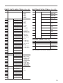
Menu ITEM Numbers and Set Values
No.
Item
Set values
59
REC CHAR POSI
0: UP LEFT
1: UP RIGHT
2: LOW LEFT
3: LOW RIGHT
REC CHAR
INFO
CAMERA NO.
0: DISPLAY
1: NO
IMAGE CONTROL MENU (ITEM No. 1 to 45)
No.
Item
1
A IMAGE
Set values
MONITOR
0: MANUAL
1: AUTO
60
2
ALARM CHANGE
0: OFF
1: ON
61
DATE
0: DISPLAY
1: NO
3
AUTO CYCLE
1 to 60
62
TIME
IMAGE
0: A IMAGE
1: AUTO
2-17: Camera1-16
0: DISPLAY
1: NO
63-78 CAMERA NAME
4
B IMAGE
5
ALARM CHANGE
0: OFF
1: ON
6
AUTO CYCLE
1 to 60
7
CAMERA CONNECTION
REC FUNCTION MENU (ITEM No. 79 to 96)
No.
Item
Set values
79
NORMAL REC
0: REC MODE 1
1: REC MODE 2
2: REC MODE 3
3: REC MODE 4
4: REC MODE 5
80
TIMER REC TIMER REC
0: OFF
1: ON
Special a)
8 - 26 MONI DISP STRUCTURE
Special a)
27- 45 PLAY DISP STRUCTURE
Special a)
INDICATION CONTROL MENU (ITEM No. 46 to 78)
No.
Item
Set values
46
BORDER LINE
0: BLACK
1: WHITE
2: NO
47
DATE FORMAT
0: Y M D
1: M D Y
2: D M Y
Special a)
81-87
TIMER
88
ALARM REC ALARM REC
89
ALARM SET
Special a)
0: OFF
1: ON
Special a)
90
REPEAT REC
0: OFF
1: ON
CONTINUOUS REC
0: OFF
1: ON
48
MONTH FORMAT
0: NUMBER
1: ALPHABET
91
49
TIME FORMAT
0: 12H
1: 24H
82-96 SETTING OF REC MODE
50
FRNT TIME DISP
0: TIME MODE
1: REC TIME
2: TIME
Special a)
FUNCTION CONTROL MENU (ITEM No. 97 to 100)
No.
Item
Set values
97
AUTO REW
0: ON
1: ON(PB)
2: OFF
51
MONI CHAR TYPE
0: WHITE
1: BLACK
52
MONI CHAR CAMERA NAMES
INFO
0: DISPLAY
1: NO
98
POWER ON REC
0: OFF
1: ON
53
DATE
0: DISPLAY
1: NO
99
BEEP
0: ON
1: OFF
54
TIME
0: DISPLAY
1: NO
100
STILL
0: FRAME
1: FIELD
55
REC MODE
0: DISPLAY
1: NO
56
TIME MODE
0: DISPLAY
1: NO
57
QUALITY MODE
0: DISPLAY
1: NO
58
REC CYCLE
0: DISPLAY
1: NO
18
a) See “Settings for special items” on page 20.
REMOTE CONTROL MENU (ITEM No. 102 to 142)
MAINTENANCE MENU (ITEM No. 143 to 152)
No.
Item
Set value
No.
Item
Set value
102
RS232C
0: 1200
1: 2400
2: 4800
3: 9600
4: 19200
5: 38400
143
SERVICE USE TAPE
0: USE
1: NOT USE
144
HARD DISC
0: USE
1: NOT USE
145
SYSTEM DATA
0: USE
1: NOT USE
146
POWER BACKUP
0: ON
1: OFF
147
MUTIPLEX
0: ON
1: OFF
148
CONT REC/PLAY
0: OFF
1: ON
149
EE MODE
0: OFF
1: ON
150
DRAM DUMP
0: OFF
1: ON
151
DEBUG INFO
0: NO DISPLAY
1: DISPLAY
152
ERROR INFO
0: DISPLAY
1: NO DISPLAY
103
PARALLEL
IN1(2PIN)
0: NO USE
104
INPUT
IN2(3PIN)
1: STOP
105
IN3(4PIN)
2: REC
106
IN4(5PIN)
3: PLAY
107
IN5(6PIN)
4: F.FWD
108
IN6(7PIN)
5: REW
109
IN7(8PIN)
6: F.FRAME
110
IN8(9PIN)
7: R.FRAME
111
IN9(10PIN)
8: SERIES REC
112
IN10(11PIN)
9: TIME ADJUST
113
IN11(12PIN)
10: ALARM
114
IN12(13PIN)
115
IN13(21PIN)
11: ALARM (L)
116
IN14(22PIN)
12 - 27:
117
IN15(24PIN)
ALARM 1(L) -
118
IN16(24PIN)
ALARM 16(L)
No.
Item
Set value
TIME ADJUST
Special a)
RETURN
TOP MENU (ITEM No. 155 to 157)
119
IN17(25PIN)
28: ALARM (H)
155
120
IN18(27PIN)
29 - 44:
156
MENU GRADE
121
IN19(28PIN)
ALARM 1(H) -
0: BASIC
1; ENHANCED
122
IN20(21PIN)
ALARM 16(H)
157
LANGUAGE
0: JAPANESE
1: ENGLISH
123
IN21(29PIN)
124
IN22(30PIN)
125
IN23(31PIN)
126
IN24(32PIN)
OUT8(36PIN)
0: NO USE 1:STOP
2: REC 3: PLAY
4: F.FWD 5: REW
6: SERIES REC
7: TIME ADJUST
8: ALARM RETURN
9: ALARM
10: TAPE END
11: TAPE EXIST
12: AUTO OFF
13: VIDEO LOSS
OUT1(15PIN)
0: OPEN
127
PARALLEL
OUT1(15PIN)
128
OUTPUT
OUT2(16PIN)
129
OUT3(17PIN)
130
OUT4(18PIN)
131
OUT5(33PIN)
132
OUT6(34PIN)
133
OUT7(35PIN)
134
a) See “Settings for special items” on page 20.
135
PARALLEL
136
OUT VOLTAGE OUT2(16PIN)
137
OUT3(17PIN)
138
OUT4(18PIN)
139
OUT5(33PIN)
140
OUT6(34PIN)
141
OUT7(35PIN)
142
OUT8(36PIN)
1: 5 V
2: 12 V
19
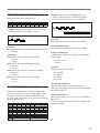
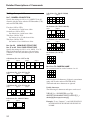
Detailed Descriptions of Commands
9 divisions (No. 20&21/39&40)
Settings for special items
page 1
No.7: CAMERA CONNECTION
Specify the settings (0: NO or 1: CONNECT) for all
cameras with four bytes after the ITEM number (37H),
and send ENTER (40H).
0
1
2
9
10
11
3
4
5
12
13
14
6
7
8
15
16
17
10 divisions (No. 22&23/41&42)
First byte (30H to 3FH):
Set camera 8 to 5 with lower 4 bits.
Second byte (30H to 3FH):
Set camera 4 to 1 with lower 4 bits.
Third byte (30H to 3FH):
Set camera 16 to 13 with lower 4 bits.
Third byte (30H to 3FH):
Set camera 12 to 9 with lower 4 bits.
page 1
2
0
5
9
4
5
8
9
12
13
2
3
6
7
10
11
14
15
page 3
3
6
2
5
4
13
7
1
0
9
12
8
10
11
15
page 2
1 2
3 4
6 7 8
10 11 12
14 15
16 17
18 19 20 21
22 23 24 25
13
page 1
1
2
3
6 7
10 11
12 13 14 15
1
page 2
12 13 14 15
16 17 18 19
16 divisions (No. 26/45)
4
8
0
page 1
5
9
page 1
page 4
6 divisions (No. 12 to 14/31 to 33)
4
8
11
13 divisions (No. 24&25/43&44)
4 divisions (No. 8 to 11/27 to 30)
page 3
10
1
3
7
6
0
page 2
page 2
0
No. 8 to 26 MONI DISP STRUCTURE
No. 27 to 45 PLAY DISP STRUCTURE
Specify the settings (0: NO, 1 to 16: MON, 17 to 32:
PB) for all division of each page with two bytes
(30H30H to 33H32H) after the respective ITEM
numbers.
page 1
page 2
5
9
No. 63 to 78: CAMERA NAME
Set a camera name for each of cameras 1 to 16.
0
1
4
8
5
9
2
3
6 7
10 11
12 13 14 15
14
16
17
Send a name of 12 characters (24 bytes) at maximum
using ASCII codes and send ENTER (40H).
Thirteenth and more characters are ignored.
7 divisions (No. 15 to 17/34 to 36)
page 1
page 2
0
1
2
7
3
4
5
6
page 3
8
10 11
9
12 13
14
15
16
17 18
19 20
8 divisions (No. 18&19/37&38)
page 1
4
20
Usable characters
The following 92 characters and space can be used.
!”#$%&’()*+,-./0123456789:;<=>?@
ABCDEFGHIJKLMNOPQRSTUVWXYZ[\]^_>
abcdefghijklmnopqrstuvwxyz{|}
page 2
0
1
2
5
3
7
6
8
9
10
11
12 13 14 15
Example: To set “Camera 1” send 34H33H36H31H
36H3DH36H35H37H32H36H31H32H30H33H
31H40H.
No. 81 to 87: TIMER
Send the following data after the respective ITEM
numbers.
First byte (30H to 39H):
Specify the day of the week (Mo, . . . Su, Mon-Fr,
Everyday, No setting).
Second to fifth bytes (30H30H30H30H to
32H33H35H39H):
Specify TIME1 (00:00 to 23:59, two digits each).
Sixth byte (30H to 37H):
Specify REC1 (REC Stop, mode 1, . . . mode 5,
Alarm REC, No Setting).
Seventh to tenth bytes (30H30H30H30H to
32H33H35H39H):
Specify TIME2 (00:00 to 23:59, two digits each).
Eleventh byte (30H to 37H):
Specify REC2 (REC Stop, mode 1, . . . mode 5,
Alarm REC, No Setting).
No. 89: ALARM SET
Send the following data after the ITEM number
(38H39H).
Fifth to seventh bytes (30H31H30H to 39H39H30H):
Set the tape length (10 to 990 minutes).
Eighth byte (30H, 32H, 33H, 34H):
Set the image quality mode (LOW, MID, HIGH
SUPER).
Nineth to twelveth bytes (30H30H30H31H to
39H39H39H39H):
Set the time mode (None, 1 to 9999 hours).
Thirtheenth to Sixteenth bytes (30H30H30H31H to
39H39H39H39H):
Set the recording cycle (None, 00.01 to 99.99
seconds).
To set the time mode or the recording cycle to None,
send 3FH3FH3FH3FH.
When both the time mode and recording cycle are set,
the time mode takes priority.
No. 155: TIME ADJUST
Send year, month, day, hour, and minute with 2 digits
each after the ITEM number (31H35H35H).
First byte (30H to 34H):
Specify Alarm recording mode (NORMAL,
INTERLEAVE, EVENT, PREALARM, FRAME).
Second byte (30H to 34H):
Specify the recording mode (1 to 5) for Alarm
recording.
Third byte (30H to 34H):
Specify the release condition (30 seconds, 1
minute, . . . Tape End).
Fourth and fifith bytes (30H30H to 31H30H):
Specify the Pre-alarm time (2 seconds, . . . 10
minutes).
No. 92 to 96: SETTING OF REC MODE
Set the cameras (0: NO REC, 1: REC) for each
recoding mode, 1 to 5, with 4 bytes after the ITEM
number (39H32H to 39H36H), then subsequently send
the following data.
First byte (30H to 3FH):
Set camera 8 to 5 with lower 4 bits.
Second byte (30H to 3FH):
Set camera 4 to 1 with lower 4 bits.
Third byte (30H to 3FH):
Set camera 16 to 13 with lower 4 bits.
Fourth byte (30H to 3FH):
Set camera 12 to 9 with lower 4 bits.
21
Sony Corporation