1
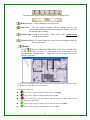
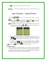
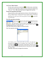
CAM LINE USER MANUAL 11.14.06 CAM v3.2 455 E. Industrial Drive Bldg #2 P.O. Box 94 Hartland, Wisconsin 53029 Technical Support: 262.369.8798 Sales & Service: 262.369.8797 eFAX: 312.602.1356 www.visioncontrols.net Vision Controls CAM Line User Manual User Controls Remote Software Playback Controls Technical Admin Controls 2 Vision Controls CAM Line User Manual ________________________________ Contents ▲ Cover Page ▲ User Controls 1. Live Display 2. Status Panel 3. Function Panel 4. Control Panel ▲ Playback 1. Preview 2. Time Date 3. Files Mode 4. Player Controls 5. Archiving to CD Using CAM CD Exporter 6. Archiving to CD Using Roxio Drag-to-Disc ▲ Admin Setup 1. Board Setup 2. Camera Setup 3. Host Setup 4. Email Setup 5. User Setup 6. Database Setup 7. My Channels Setup 8. Sound Bank Setup 9. Address Book Setup 10. Program Setup 11. E-Map Setup 12. I/O Setup 13. Vision Controls Server Setup ▲ Technical 1. DVR Connections 2. Software Upgrades 3. Remote Software Setup 3 User Controls – Live Video Display : This icon signifies which camera is active (selected). Click on the selected camera, this icon will be shown on the top right hand side of the selected camera’s display. : This icon shows that the camera is under “Schedule Recording” Status. : This icon shows that there is an alarm on the corresponding camera. : This icon shows that the camera is under “Recording” Status. The icon will not be shown when the camera is under “Monitoring only” mode. : This icon shows that “Live Audio playback” is active on the selected camera. If you select a motion detection area (by clicking on the original point, holding the left button of the mouse, dragging it to the desired point, and then releasing the button.), the system then undertakes motion detection against the selected area. The mask area in the photo on the left is the motion detection area. The green color frame means that no alarm is triggered. In the left photo, the detection area is shown in red color, this means that an alarm is triggered. 4 The detection area in the photo on the left is shown in blue color, to show that the mask detects motion, but not enough motion has taken place to trip the alarm. The above screens indicate when the camera in not recording and is still idle; the camera is working, but the view is not displayed (recording still); and when the camera is not connected video lost. Resizing the Video Display Window: To resize a live video display window double left click on it. The will blow the window up to 640 x 480 double left click again to bring it up full screen, double left click again to bring it back to its original size. 5 User Controls – Status Panel The Status Panel is located in the bottom middle portion of the application. Click the left mouse button once to hide the status panel as the picture below: Click the left mouse button again to display the status panel as below: The Status Panel mainly includes the following display items and functions: • Host: Displays the name of the Host computer in control now. It can be a local host or remote host. means the machine is not yet connected to a server. means the machine is connected to a server. • Free: Displays the active hard disk drive and space available on that drive. If the hard disk free space is not enough, it will be displayed as “No Space”. • Auto Scan: When this icon is displayed it means the auto scan feature is enabled. • Current Time: Displays the current date and time. • Camera Status: Displays the selected (active) camera position, video/audio recording status. Image Function Icons: Image function icons include Unmask Motion Detection Snapshot, Caption, Caption Color, and Video Configuration. Area, Unmask Motion Detection Area Pressing the camera. button in the status panel will remove any motion masks associated with the selected Snapshot This button is used to take a still picture (snapshot) on the selected camera. This picture is automatically saved under the date folder under a picture folder within the files mode playback menu. Caption 6 Click the button to display camera name, recording time and current time as shown to the left. Click the button again to hide the caption. Caption color You may change the color of the caption on the selected camera by clicking the button; the window to the left then appears; select the desired color and then click the OK button. Video Configuration This button lets you change the video configuration of a camera. Click the button. The video configuration dialog will pop up as shown to the left. Simply drag the respective buttons to adjust the image’s brightness, contrast, saturation and hue. To return to the system to its default settings, click the Default Colors button. 7 User Controls – Function Panel Explanation for the buttons for the main pane: The application will be minimizing after pressing this button. A camera icon will be shown on the bottom right hand side of the Windows system tray. Full Screen: The image will be enlarged to a full screen display mode when pressing this button. Press ESC key to return to original screen size. Exit: Exits the program and shuts down all recording. (Only System Administer can use the exit function.) Minimize: Record: Pressing this button will start recording on all active cameras Stop Recording: Pressing this button, it will stop all video/audio recording. Log In/Out: When running the application, the user’s password is required before one can perform the applications functions. When a user needs to be away and does not want others to have access to the system, he/she may logout of the system first. After this is done all the system functions will not be accessible. When a user logs out the application will automatically display as a full screen image. The user will then need to press the ESC button to re-login. The login dialogue box will then again appear. After the correct password and user name is entered the user controls will then be brought back up. Playback: By pressing this button, the playback functional panel will appear as shown below: The Playback panel will be explained in detail in the Playback section. Displayed or Hide function panel button: When you click this button the first time, the function panel will be displayed as below: 8 Click this button again to hide the function panel as shown below: Remote Access: Allow linking to Cam XP host site. Auto Scan: The live camera displays will be enlarge one by one automatically and displayed when this button is clicked. This will not influence the recording. System Setup: Setting of the System. Please refer to the Admin Setup section for more detail. Alarm/User Log: This button brings up a log of users who logged in and out and camera alarms. E-map: Click button, the following E-Map dialog will be show. Double click on the camera logo on e-map. It will switch to the main picture of the correspondence computer (host). Right click on the camera to the see the camera’s properties. As shown on the left hand side of the above picture, this tree form graph is used to select the e-maps for different level when there are 2 or more e-maps. Camera Logo explanation: (Grey Camera, light on) indicates that the camera is recording. (Grey Camera, Light off) indicates that the camera is idle. (Grey Camera and a Stop sign) indicates that there might be a faulty setting for host name, Board ID, or camera ID. (Green Camera, Light on) indicates that the selected camera is recording. (Green Camera, Light Off) indicates that the camera is idle. 9 (Exclamation mark) indicates that an alarm has been triggered. Mute: alarm. Shut down all audio outputs from the sound card caused by an User Controls – Control Panel The following panels as shown below; buttons in the control panel are used to change to the different Host: Click the button to change to Host control Panel; or when under the My Channel control panel, select the last page/ next page. The Host Panel is used to switch between networked DVRs. My Channel: On the bottom of the host inside the main screen there is an up or buttons, the panel will change from and down arrow, by clicking the the Host panel to the My Channels panel as follow. • • The user can then double click on any of his/her pre-created views. Next click the REC button, the live display for all associated cameras will then come up. Click the Stop button; the cameras from the remote hosts will be stopped and displayed as idle. To change to another My Channels view simply double click on a different name, and press the REC button. The original My Channels view will continue to stream / record unless the Stop button was clicked prior to changing views. PTZ: Click the button, this will bring up the PTZ control panel. Direction Control The PTZ control panel provides 8-direction control. Move the cursor to the button for desired direction and hold the left button of the mouse to perform the desired turn. When the button is released, the movement stops. Some dome cameras may support only 4 direction control, i.e. Up/down, right/left. 10 Iris, Focus, Zoom Control Move the cursor to the desired control button and hold the mouse on left button to perform the desired operation. When the button is released, the operation also stops. The circles to right of Iris and Focus are used to activate the “auto-iris” and “auto-focus” control. Some dome cameras may not support these functions. Preset Point operation and setup. Only pan-tilt dome cameras support the Preset function. Click the Mem button on the PTZ control panel, the camera will then move to the preset point. Dependant on the type of dome camera, a maximum of 32 preset points can be set. To set the preset points, move the camera to the desired position, and click the button on the PTZ control panel. Auto Pan operation and setup The auto pan function moves the camera horizontally between two points. Click button to the right of Auto button on the PTZ control panel to pop up the dialog to enter the setting. Specify the preset start/stop points and the camera pan speed. Click the OK button to complete the setup. Some dome cameras may not support the auto-pan function. The Cruise operation and setup After finishing setting up some preset points you can have the application cycle through those pre-defined presets in a set pattern. This is called “Cruise”. Click at the right of the Cruise button on the PTZ control panel to open the Cruise Setup screen. Select the first preset point and then enter the dwell time. Next click the Add button to complete the setup. Repeat this process for each preset you want to add to the “Cruise” (tour). Some dome cameras may not support these functions. 11 Output Port Control Panel: This control panel is used to control the output port for the associated DVR. You can click arrow to select an then click the output point name to turn that output on/off manually. (Output ports are generally used to control external I/O devices) 12 Playback – Preview An easy way to play back recent video is to use the preview feature. To do this select the desired camera by left clicking on it. Then click the right button of the mouse, and select Preview. The following will show: Enter the amount of minutes the user desires to go back. Time range for preview is 1~99 minutes. If there is no corresponding recorded video, the system will automatically search for the earliest file for playback in the time range. When there is no valid recorded file saved due to a short recording time, or when there is not a video file in the appointed time, an invalided messages will be shown. While remote monitoring the preview function will only be available if the user selects record as opposed to monitor only. 13 Playback –Time Date In the following description, you will be able to find the saved video file and load picture function as follow. 5.1 Video Playback Click button. The system panel will switch to the playback panel as shown below: From here a user can search for the video files they want to playback, but they will need to input the Host ID and the search option. Playback Modes Search By Date: Use this mode to search for video files by date (including year, month and day). Search By Time: Use this mode to search for video files by the start/end date and time (including year, month, day, AM/PM, hour, minutes and seconds) Search By Camera: Only the cameras which had saved video files can be selected. If no files is linked to a given the camera the dialog box next to that camera will be greyed out. Note: A maximum of 4 cameras can be chosen at one time. After selecting the searching parameters, click the Play button to play. 14 Playback – Files Mode Files Mode button on the Playback Panel will bring up the Clicking the following screen. The screen will be divided into a left and right section. The left displays the date folders. The right displays the saved video files. In the files mode the folder levels are as follow. - Host: The top level is the host name. Database: The second level is the database. Date: The third level is the date folder. Host Name: The fourth level still uses the name of the host. This host name is the host where the video files were saved from. - File: The fifth level consists of three folder names, Video, Picture, Alarm and Clip. Continuously video files are saved in the video folder. The picture folder stores the snapshots. The alarm folder stores the files created when an alarm was triggered. The Clip folder stores any clips created. When you have successfully found the video files there are several functions you can then use to manage these files. Open File: In the file mode, 4 videos can be played simultaneously by highlighting them then clicking on the Open button. Download: Select the video files from another host’s database; by clicking the Download button, you will then be able to transmit these video files to the database on your local computer. Export: Select the file you wish to export then click the Export button. Next select the folder / drive you wish to export the video files to, then click the OK button. Delete: To delete a video file(s) highlight the file(s) then click the delete button. Close: Click Close to exit the files mode. 15 Playback - Player Controls The playback window consists of four parts, including Message area: Includes the relevant information such as host name, time zone and operating status. - Host Name and Time Zone - Recording date for Video File - Operating Status: Includes “playing” “pause” “stop” etc. Video Playback: Includes the information such as time, board names, and camera names. - Displays the start date/time of the file. - Displays the end date/time of the file. - Display the date/time of the current display. Playback Time Scroll Bar: This displays the relative time position of the current display in the video file. You may speed up the playback by dragging the time pointer using mouse or by the skip prev / next buttons, Playback control panel: When pressing the button, the extended function panel will be shown as below. Press the button again to hide this extended functional panel. Each playback function button is described as follows: 16 Stop This is used to stop playback. Play This button functions the same as the Play button of a traditional video player. When clicking this button during fast or slow playback, the playback speed returns to normal. Pause This button functions the same as the Pause button of a traditional video player. By clicking this button during playback, the playback pauses. To continue the playback, re-click this button or the play button. Backward Search This button functions similar to the Rewind button of a traditional video player. Click this button, and the video will skip backward for a number of frames (160 frames). Forward Search This button functions similar to the Fast Forward button of a traditional video player. Click this button, and the video skips forward for a number of frames (160 frames). Forward with single Image When this button is clicked, the video will move forward a single frame each time. The video will be paused until the play button is clicked. Backward with single Image When this button is clicked, the video will move backward a single frame each time. The video will be paused until play button is clicked. Then the playback speed will be back to normal. Snapshot By clicking this button, you may capture still images during playback. If there is caption text on the video, the captured images will contain the caption text information. The captured image is stored in a BMP or JPG format. Start Video Clip Clicking this button during video playback will mark the start of a video clip (event). This time will become the start of the video clip. 17 End Video Clip Clicking this button during video playback will mark the end of a video clip. This time will become the end of the video clip. Save the Video Clip Clicking on this button will save the current video clip. Playback clip After the video clip has been saved clicking this button will replay the clip. Caption Click the icon, the playback window shows the name of the board / camera, the starting time, ending time, and current time. Caption Color Click the icon; the user can change the color of the caption. Zoom In You may click this button to enlarge an image from its current size. Each click will enlarge the size by 25% up to the 200%. Zoom Out You may click the button to reduce an image from its current size by 25% down to 100%. End Click this button to stop playback and close the player. Fast playback and slow playback to the left is the control panel for playback speeds. The middle setting plays at a speed of 1x. Clicking to each point to the right of 1x will increase the speed from x2, x4, High Speed and Extra High Speed. Clicking each point to the left of 1x will reduce the speed from 1/2, 1/4, 1/6, and 1/8. 18 Playback – Archiving to CD An incident has occurred and you now need to get the video into the hands of the proper personnel. How do I do this? Simply follow the instructions bellow: Click the play button. This will display the following search bar: Select search by time, set a date and time relative to the start of the incident, then press the Play button. This will launch the player as illustrated in the picture below: Once you have located the start of the incident you can create a clip of that incident. To do this button. This will bring up a subset of controls as shown below: click the To start the clip press the where the clip has started. button. This will create a tick mark on the scroll bar identifying To end the clip press the button. This will create a tick mark where the video clip ends. button. This saves the video clip Once this is done you can save the clip by pressing the under the same date folder as the original file under a directory called Clip. 19 To review the clip you just created press the application. Click the button. You can then close the player button in the lower left to return to the main screen. If Using CAM CD Exporter To Create CD/DVD: Vision Controls has updated its CAM software with a CD Exporter application. This application was designed to simplify the CD burning process on all CAM DVRs. The application is installed on all DVRs that shipped after Jul 1st 2006. Using the CAM CD Exporter Plug-In The application runs in the upper left hand corner of the CAM software. 1. To open the application, double-click on the CD icon in the upper left hand corner: 2. This will open the menu interface shown below: 3. From this interface we can specify a start time and end time to search upon: 20 4. Quick range can also be used to easily select a time frame (note: this will auto adjust the start and end time correctly). 5. Once a time frame is selected the user can then select which cameras they want to search upon using the checkboxes as shown below: 6. Clicking on “Find Video” will then display the search results for the specified camera(s) as shown below: 21 7. From this menu a user can review the displayed video by double clicking on the video file. To toggle through the video easily click the “View” button and select “Player”. This will load all of the playback controls. The user can then use the slider bar to quickly scroll through the video file as shown below: 7. To get back to the exporter application, double-click on the CD icon in the upper left hand corner. The user can then select a file and choose to copy it to the burn queue by clicking the “Copy to Burner” button. 22 8. Here the user has the option to remove items to the burn queue or continue to add additional video files by selecting them and clicking the “Copy to Burner” button. Clicking the “Burn” button will bring up the following menu: 9. From this menu insert a blank CD and click Æ Next Æ Next Æ Finish. This will burn the copied video along with the player on a blank disc. 23 If Using Roxio Drag-to-Disc To Create CD/DVD: Next click the minimize button located in the lower right hand corner. This will take you to the standard windows desktop. Click the arrow in the lower right hand corner to display all of the hidden icons. Double click on the CD. This should bring up the following (or similar) application. Find the Player.exe file and drag it to the CD, this will copy that file to the CD. (The Player.exe file will either be located on the desktop or in the C:\Program Files\Cam SS XP\ directory) When this process is completed the “CD” on the Roxio application will stop spinning. You now have a preformatted Cam SS CD. Using a pre-formatted Cam SS CD: Call 262-369-8797 if you wish to purchase Cam SS preformatted CDs. Within the Cam SS application, click the playback button. Then click the files mode button. This will bring up the Files Mode playback view. 24 From here you should click on the + next to Cam SS Host, then click on the + next to the video folder, then the desired date. Next select the Video, Clip, or Picture folder, then click on the file once to highlight it. When the desired file(s) is highlighted click the export button. This will bring up the following menu: Use the drop-down menu to select the CD, then click OK. Click Ok again to use the default name. Then click the eject button on the CD Drive, wait 1-5 minutes when the CD ejects the copy process is complete. 25 Admin Setup – Board Setup Click the button to enter System setup. System Setup has tabs labeled Board, Camera, Host, E-mail, User, Database, My Channels, Sound Bank, Address Book, Program, Emap and I/O. This chapter will cover the options available in these tabs. Board Setup The Board tab appears as shown. This example reflects a DVR with eight channels. Video Standard: This defines the type of camera and signal standard used, NTSC or PAL. The frame size for NTSC is: 640x480 for XP cards and 704 x 480 pixels for MP4 cards The frame size for PAL is: 704x576 Name: The default board names are Board 1-Board 4. This name may be changed here as needed. The name can be displayed as an overlay on the video and to simplify identification of the video source. Recording Speed: This sets the rate at which frame are captured in terms of “Frames Per Second.” The frame rate can be reduced to decrease the disk storage requirements and increase the retention period for stored video. XP boards have a frame rate that varies depending on the number of channels in use and the amount of motion on those channels. Due to this and the fact that XP cards have a maximum capacity of 30FPS per card, they have a practical limit of 7-8FPS per channel when all channels are in use. If a lesser number of channels are in use, 26 the maximum FPS may reach 10 To strictly limit the frame rate for the channels on an XP card, the FPS must be set at 7 or less. XRT, MP4 and RT4 cards have a full capacity of 30FPS per channel. Lowering this value will reduce the frame rate on all channels on that board. High Quality Recording (HQ): When High Quality Recording is selected, image quality is improved while disk storage requirements increase dramatically. Exit: Click OK to save your changes Admin Setup – Camera Tab Complete the Camera tab before beginning to record. Select the cameras (channels) you would like to use, give them each a meaningful name and select: (RDAL) “Record”, “Display”, “Audio” and “check video Lost” as required. Each camera is uniquely defined with these options. Camera Tab Options Camera Name: A user can set the camera name for easier identification of the camera when viewing live or searching through old video. R - Enable Video Recording: Select this to record video on this channel. When Display is selected but Record isn’t, live video will still be visible on the DVR and any remote clients connected. D - Display Video Image: Select this to display live video on the DVR and remote clients. When Recording is selected but Display isn’t, the word “Working” will be displayed on the DVR and any remote clients connected to the DVR. A - Enable Audio Recording: Select this to record audio. XP boards support two 27 channels of audio while XRT, MP4 and RT4 cards support four. A special breakout cable unique to each card type is required to connect the audio input channel. These cables have a female RCA jack for each input. L - Check Video Lost: Select this to automatically detect the loss of a video image. Video lost will be displayed on the screen and can trigger an alarm as you require. Video lost may be reported when the source fails (camera off, cable cut, cable disconnected) or when the camera is in total darkness. Enable Alarm: Select this function to enable the “Video Lost” alarm function for this camera. Once selected, press the Setup button in the Alarm column to explore the available alarm notification options. PTZ Control PTZ cameras can be controlled from the DVR or authorized remote clients. An RS-232 to RS-485 provides the interface from the COM1 or COM2 port of the DVR to the camera. The specific PTZ protocol, “Baud Rate” and RS-485 address to be used are defined in the I/O tab. After being defined in the I/O tab, the definition is selected here by name to associate the camera with the PTZ control. Image Setup: Click the setup button, and the Image setup dialog will appear. - Image Quality: This lets you adjust the image quality by sliding the bar to the left or right. High image quality = low compression ratio and a larger video file sizes. Low image quality = high compression ratio and a smaller video file size. - Sensitivity: This adjusts the sensitivity of alarm triggering based on image subject characteristics such as the image quality, distance, light, and object size. Note: High sensitivity may cause false alarms as well as increase the video file size. When adjusting sensitivity, consider the image quality and surrounding environmental conditions to avoid false alarms. - Number of the changed pictures: This defines how many consecutive frames must contain motion to trigger an alarm. One is sensitive whereas ten is less sensitive. 28 29 Admin Setup – Host Setup The following setup menu will appear when Host is selected. When I startup my computer/Automatically launch Cam SS XP: Automatically start the DVR application (Cam SS XP/MP4/RT4) after a reboot. When I run Cam SS XP/Automatically Record: Automatically start recording after starting the DVR application. When I run Cam SS XP /Automatically connect to server: Automatically connect to the Cam SS server after starting the DVR application. When I close Cam SS XP/Automatically power off the system: If this function is enabled, Windows will be shut down when a System Administer ends the DVR application. When I close Cam SS XP/Automatically reset the system: If this function is enabled, Windows will be shut down and restarted when a System Administer ends the DVR application. Soft auto reset system/ Automatically reset the system: If this function is enabled, Windows will be shut down and restarted once a day, once a week or once a month at the schedule time. Click the Setup button to display the “Automatically reset” options and define the reboot schedule. 30 Pop up alarm log when alarm: While enabled, the alarm log will appear when an alarm is triggered. Video File Length: The length limit of a video file can be set from ten minutes to two hours. This is the length of the recording time, not the size of the file. When the specified time has expired, a new file is started for each camera. If you set this too short, the time spent searching based on date/time may be increased. The difficulty of file management may also increase with the number of files. Large files may not be optimal either if they will be accessed remotely over a slow network connection. The general consensus is that the optimal file length limit is 60 minutes. Auto Scan Interval: Scan mode allows a user to automatically cycle between enlarged views of the cameras at a fixed time interval. The Auto Scan Interval defines how long each camera will be enlarged and displayed when using Scan mode. The default time is button at the bottom of the window to start/stop Auto 30 seconds. Click the scan. Live Audio: This enables audio processing system-wide. The inputs on the breakout cable are color coded and specifically associated with certain channels/cameras. In the Camera Tab, the audio setting for the appropriate camera must be selected to enable recording for that camera (actually RCA inputs.) With Board 1 as an example: XP Board: Red = Camera11, White = Camera12 XRT/MP4/RT4 Board: Red = Camera 11, White = Camera12, Black = Camera13, Yellow = Camera14 Water mark: When selected, the recording will include a visible “watermark”. The watermark will be visible when displaying live or recorded video or snapshots. The purpose of the watermark is to preclude alteration of video clips or snapshots. Depending on the degree of contrast in color between the background image and the watermark, it may not always be easily visible. Display encoding status: When display encoding status is enabled, the recording speed for the selected channel will be shown on the control panel at the lower part of the screen. This is a snapshot of the frame rate at that instant in time. This does not represent the average recording speed as it will vary depending on the type of capture card and the amount degree of motion in the image. 31 Webcam: (Only software versions 2.x or later support this) Select this to provide access to live video using Internet Explorer. The procedure to acquire and install the required Internet Explorer plug-in is documented separately. 32 Admin Setup – Email Setup Alarm notification can be accomplished using email. Messages, attachments or snapshots can be sent to a predefined email address based on the occurrence of an alarm. This technique can be used to transmit a video clip to another site prior to the possible destruction of the DVR by the subject of the clip. Mail Server: The mail server name, sender email address and recipient email address to be used are defined here. You must provide or contract with someone to provide an email server and the necessary permissions to use that server. This must be a server that supports the SMTP protocol. Most email servers including Microsoft Exchange support this. This should be the same process you would typically go through to obtain a personal email address from a public ISP or your internal company email support group. E-Mail From: Enter the email address you’ve been given for sending email in the preceding step. This will let the recipient know who is sending this e-mail. A valid address is required, it cannot be left blank. E-Mail To: Enter the recipient’s email address. This must of course be a valid email address to facilitate delivery. E-Mail Retry time: To accommodate network or server outages between the DVR and the email server, the DVR will retry delivery until this value is reached. Specify the number of times the DVR should retry delivery. The default is three but should probably be much higher depending on your requirements and the reliability of the network and email server involved. 33 E-Mail Retry Interval: This is the delay between email delivery retries. The default is 60 seconds. A much higher number is recommended. The number of retries and the interval can be multiplied to calculate the period of time over which the DVR will retry delivery. Make this realistic depending on the reliability of the email server and the network involved. Mail Server Authorization: If the email server you will use requires login via username/password prior to sending email, enter it here. If the mail server does not require a login for sending email, leave this blank. Modem Connection: If the mail is to be delivered through a modem connection, you must first define the modem in Windows “Dial-Up Networking”. Now the modem definition is available in the “Connection select” menu and you can enter associated username and password for the dial-up service. When an alarm is triggered, the DVR will establish the dial-up connection, deliver the email automatically and disconnect when complete. Camera Trigger: Here you can activate the delivery of video clips and/or snapshots by email. These deliveries are triggered by motion alarms on selected cameras. To enable this feature, select the desired camera and content type, video clip and/or snapshot. z Camera Selection: Cameras with the alarm function activated (in the Camera tab) will be available for selection. If the camera is selected here without V or P selected, the email will be sent with the alarm text only. z V - Sending Video Clips: V stands for Video Clip. When V is selected, video clips generated will be sent via email. The length of the video clip is defined in the alarm setup for the camera in the Camera tab. z P - Sending Snapshot: P stands for Picture, which is a snapshot from the video. When P is selected, snapshots generated will be converted from *.bmp into *.jpg files, reduced in size and included in the email sent. The number of snapshots is defined in the alarm setup for the camera in the Camera tab. Input Trigger: With this selected, an email will be generated when an Input on the VGIO I/O interface is closed. This refers to a contact closure on the ten pin header on the capture card. Further information on the proper use of this interface is available from Vision Controls upon request. 34 Admin Setup – User Setup Select the User tab in System setup. The red colored head represents the System Administer name chosen the first time the application was started. New User Setup Select New to add a user. The User Info dialog will appear. (Only the System Administer can add, delete or edit a user). 35 Complete the User Info: ¾ User Name: Enter the user name ¾ Password: Enter the password ¾ Confirm: Enter the password again for confirmation “Audit” settings control the features available to this user. To grant access to specific features, select one or more of the following. ¾ Start: Grant access to Start Recording and Stop Recording ¾ System: Grant access to System Setup and Video Configuration ¾ Guard: Grant access to Unmask, Audio and Snapshot ¾ Log: Grant access to Alarm Log and User Log ¾ Playback: Grant access to Playback, Search, Load Picture, Text and Text Color ¾ I/O: Grant access to I/O device control ¾ PTZ: Grant access to PTZ controls ¾ E-Map: Grant access to E-Map ¾ Remote Access: Grant access to remote monitoring ¾ Camera Selection: Grant access to the selected camera. If the camera is not selected here, it will not be visible to this user. Stored video for restricted cameras is still available. When complete, click OK to save your changes. The next time this user logs in, these permissions will be in effect. Note: User permissions are the same for local and remote users. Editing User To modify passwords or permissions, select the user name and click Edit. Note: Normal users can only change their own password not their permissions. Only the System Administer can modify user permissions. Delete User Select the user to be deleted and click the Delete button to delete a user. Only the System Administer can delete a user. 36 Admin Setup – Database Setup Here we define the disk and folder in which video files are stored. Multiple disks with one folder per disk may be defined. Adding A New Database Click on New and complete the following: - Name: Name this database location Directory: Click … to select the disk drive and the folder in which video will be stored - HDD reserved Space: The minimum space that can be reserved on a disk partition is 1000MB. The maximum is 9900MB. For Cam XP systems, reserve at least 1% of disk partition. For Cam XRT, MP4 orRT4 systems, reserve at least 5% of the disk partition. - Recycle: With recycle selected, the oldest days worth of video will be deleted to make room for today’s video. - Alarm when space not enough: With this selected, an audible alarm will be generated when the disk partition is full. Select a warning sound (any *.wav file) by pressing … . When the drive partition is full, the system will play the warning sound. - Click OK to save your changes - Note: Only one database location can be defined in each disk partition. To improve the reliability of your system, do not create video partitions on the operating system drive or use it for recording video. This will lessen the wear on and possibly lengthen the life of that drive. 37 Admin Setup – My Channels Setup The My Channels Feature allows a user to create a customized view consisting of multiple cameras from multiple DVRs. Creating a new “My Channels” Select New to add a My Channels. The “Add New My Channel” dialog will be pop up as below: 1) Name: Name used to setup My channels combination 38 2) Content: Notes field 3) Split screen: This is used to define how many video windows the display will consist of: 4 divisions: A, B, E and F 9 divisions: A, B, C, E, F, G, I, J, and K. 16 divisions: All 16 positions from A-P. 4) Record: This is to set whether the monitoring video will be recorded locally and saved. 5) Host: This is used to define which Host (DVR) you want to the selected camera resides on. 6) Camera: This menu is used to select a specific camera to add to the My Channels view. Content: This is an additional notes field. Admin Setup – Sound Bank The sound bank is a collection of sounds the application can use for alarms or other event notification. New Sound: To add a new sound file, click New Sound and the following dialogue box will appear. First, give a name to the sound file, and then click Select to choose a sound file. 39 After a sound file is selected, Click Open then it will return to the following screen. Click Preview to ensure the selected file is a right one. Then Click OK to complete the setup. Admin Setup – Address Book The Adress Book can store remote telephone numbers or remote IP address that can be used other places within the application. Adding a New Entry To Address Book: To add a new entry to the address book, click Add the following dialogue box will appear: 40 Adding a new server: Select Server from Type field; and then, type the IP address into the field, Phone No. /IP address. Finally, click OK button to finish the setup Adding a remote IP: Remote IPs are used to send remote alarms to. Select Remote IP on the Type pull-down list. Verify that the name is identical to the machines actual host name. Click OK to finish the setup. Adding a Modem: The modem communication is used for remote access and remote alarms. First, input the name of the modem; second, select Modem on Type pull-down list; third, input the remote CAM System’s phone number/IP address. Last, click OK to finish the setup. After the user has finished setting up address the following screen will be shown:: Click OK to return to the main menu. 41 Admin Setup – Program Setup The program feature is used to schedule recording and alarms to be active only during set periods: New Recording Schedule Click Add and the following dialog box will be shown: Enter start date/time and end date/time into the “From” and “To” fields respectively. When entering the date/time, you may type them directly into the fields or click the up/down arrows to the right of each one of the fields. Select “Repeat Mode”: One selection only: (Only Once, Every Day, Every Week, or Every Month) Note: If the desired schedule time crosses 12:00 is recommended to split the schedule into two, Split PM6:00:00~AM9:00:00 into PM6:00:00~PM11: 59:59 And AM12:00:00~AM9:00:00. Recording Mode: - Recording: Normal recording mode. - Audio Recording: Simultaneous audio recording with the video recording. - Snapshot: It makes the system take snapshots at a predetermined time interval. - Interval: This is the time interval for snapshots. Default is set at 10seconds. - Camera selection: This is to select the required cameras for the above schedule for recording. 42 Once a user clicks OK the newly created program will be activated. Admin Setup – E-map Setup The E-Map feature is used to create an interactive map of camera positions and DVRs. Add an E-map: Click the New button then the Add New E-Map dialog will pop up. Firstly enter a map name. (ex. 1st floor, center court etc). Then click SELECT to select the map file. The Map files have to be a .BMP format; the map resolution should be set at 640 x 480. After this is finished click the OK button. The Edit E-Map dialog box will then pop up. Edit E-Map: Select the E-Map name then click the EDIT button. 43 - Add Camera: To add a camera onto the map, click button on the left upper corner; the cursor will then turn to a “+”, Move the cursor to the desired position and then click the left button of mouse to add the camera. As illustrated above, the red arrow points to the newly added camera. After setting the camera, the Properties dialog will pop up. - button, the camera properties Camera Selection: Double click the dialog will then pop up as shown below. Here you need to enter the correct Host (DVR) using the drop down list, then select the corresponding camera. - Level Setting: The level button is used to link additional maps together. Select the button on the left upper corner to add the level button to the map. The cursor then turns to “+”, Move the cursor to the desired position and then click the left button of the mouse to add the level. After adding the level icon, the map level property dialog will pop up. Map Level Selection: Double click on the level button, a drop down menu will then appear. Use this menu to select another map. - 44 Admin Setup – I/O Setup Click System Setup from the Setup Functional Panel, the system setup menu will pop up. Select I/O device and the following menu will show: RS232/RS485 interface I/O device: We support PT811 input device. 8 ON/OFF inputs, 8 digital output modules; address range: 0x01-0xFF. Each PT-811’s address must be different from that of any other PT-811 on the same COM port to avoid error in control. Speed Dome Camera: This system can simultaneously control up to 16 Pan-Tilt dome cameras. The camera brands that we support are as follow. - DynaColor CA720 speed dome camera - Lilin PIH717X speed dome camera - Pelco-D or Pelco-Pdome speed dome camera - Mikami PTC103A speed dome camera - Sensormatic speed dome camera (RS422 Interface) - Phillips CSS speed dome camera (Requires Philip’s own RS232-485 converter. Other converters might not be able to connect and control the Phillip’s camera) - SamSung speed dome camera - Panasonic WV_CS850 speed dome camera The address range for each speed dome camera is different, please refer to its user’s manual for address setting and control signal connection details. VGIO Each capture board has 8 digital inputs and 8 digital outputs along with a watchdog functions. Adding an I/O device Click the New button to add a new I/O device. 45 Devices can be separate into two types, IO devices and PTZ camera. - Device name: Give the device a name for easier identification. - Device type: Select the type of I/O device using this drop down. - Connect port: Select the COM port you wish to use to communicate to the device. - Hexadecimal Address: Enter the camera you wish to controls address in HEX When finish, click the Ok button to saved and exit the screen. Setting up I/O Device Double click the desired device to pop up the I/O Device setting dialog. Watchdog Function VGIO provides a watchdog feature. This sends a reset signal to the PC main board. If the computer locks up or our application crashes this will send a signal to the PC to restart. Output Port Signal Type Setup Select output port number, the Output Port setup dialog will pop up. - Output Port Name: Setup the Output port name. - Use PTZ Control: Select which PTZ control this output port will use, then select what you want the camera to do: up, down, left, right, zoom in and zoom out etc. - Port Type: z Signal 1: Low to high (Off to On). Defaulted. 46 z z z z Signal 2: High to low (On to Off). Pulse 1: Positive pulse Pulse 2: Negative pulse Signal 3:Toggle Signal 3 (toggle) is for switching the external device ON and OFF. If the external device is ON, user can control the output port to turn it OFF. If the external device is OFF, user can control the output port to turn it ON - Pulse setup: z High Period: The default frequency is 1 second while the upper limit is 999 seconds. z Low Period: The default frequency is 1 second while the upper limit is 999 seconds z Pulse number: The default number is 1 while the upper limit is 99. - OK: Click OK to confirm. Input Port Mode Setup Click on an input point number, the input port mode dialog will pop up: - Input port Name: Setup the input port name. - Port Type: Trigger mode selection. z Alarm Switch: Manually trigger an alarm. z Trigger alarm: When an alarm signal is detected, it will trigger the set alarm action. - Activate by a scheduled table: This input port can be set to only be active during scheduled time periods. - Play Alarm Sound: Click select, the sound selection dialog will pop up. Select the desired sound file then click OK. - Activate Local Recording and Remote Alarms: Select the camera number, the Input trigger alarm camera setting will then pop up. z Start Recording: If the selected camera is not set to do continous recording this option will start recording on the selected 47 camera. z Trigger to preset: A pan-tilt dome camera can be set to jump to a pre-defined preset upon the triggering of an alarm input. You can designate a “dwell” time when this time has passed the camera will then return to the selected (back) preset. - Enable Output Port: Upon the triggering of an input you can trigger a set output. This can be used to control external devices. Admin Setup – Vision Controls Server To monitor a remote DVR’s live display, or to transmit an alarm through LAN, Internet or Intranet, the Vision Controls Server program must be used. Starting the Vision Controls Serve Double click on the shortcut icon shown below, or set the server to start automatically on boot. The first time you run the Vision Controls Server the following dialogue box will appear: The username and password entered at this time will be considered the system administrator. System Administer A system Administer owns the highest access privileges and can add or delete all users as well as edit current users’ access rights. Note: Make sure you keep the administrators username and password, if for some reason the system administrator forgets his/her password you will need to re-install the Vision Controls Server application. Basic Vision Controls Server User A basic user can only start the Vision Controls Server program, not add or delete any users. 48 Login / Logout Before you leave the computer, we suggest you logout Vision Controls Server program. To do this click on File Æ Logout. Adding a New User: Click File command and a pull-down menu will be show as follows: Click User Information to open the User Information window. Click mouse on the right button to add a new user and the Add user dialogue box will appear as follows: Enter the user’s name, password and confirm password. Click OK to finish the setup and to exit the add user window. Editing and deleting a user The System Administer can click directly on the desired user in the tree structure, and then click the right button of the mouse on it. Then the Edit user and Delete user menus appear. The System Administer can reset the user’s password or delete the user completely. 49 The Connection Contents Click on the button, this will show all of the active users connected to this Vision Controls Server: Exiting the Vision Controls Server To exit the server, the program will demand that the user input his/her password as a confirmation in order to avoid accidental or unauthorized termination. IP Management The IP Management feature is used to manage who is allowed access to the server. Click IP Manage and select setup. IP Management modes are as follows: 1. Shield the IP address listed below: IP addresses listed here are the only IP addresses not allowed connect to the server. Under this mode, all other IP address are allowed to connect to the server. 2. Open the IP address listed below: IP addresses listed here are the IP addresses allowed to connect to the server. Under this mode only the IP addresses listed here are allowed access, all other IP address will not be allowed to connect to the server. Add: Click the NEW button, the Add IP address list dialog will pop up as shown below: 50 The new IP address can be broken into 3 categories. - Local Host: Means the local host connected to the same server. - Remote Server: This means the remote server you want connected to the local server (this feature is used to chain multiple Vision Controls Servers together as shown below) - Remote Host: This means the remote host connecting to a different server. By using the “Connecting to other Vision Controls Server” feature from the server application you have the ability to chain two different networks together as shown below. This can let the hosts in a different network communicate and transmit files, or live video streams from one network to another through CAM application. 51 Technical – Software Upgrades With the most updated version of Vision Controls software, please follow the steps below to upgrade your software. Uninstall the old version Use the Add/Remove Programs application located in the Control Panel program folder in the Windows to remove the previous version of software. Select the Vision Controls Application then click the Remove(R) icon to remove the program. The image and configuration files are not actually removed during the process of uninstalling. The user may use File Explorer method to check the directories under C:\Program Files\Vision Controls (we assume it is the directory selected in previous installation). Note: In order to prevent abnormal execution of the new version of software, it is recommended that all of the configuration files located in the C:\Program Files\Vision Controls directory be deleted. Installing an updated version of software Before installing Chateau application software, please ensure that the driver files for the capture board have been updated to the correct rev. 1. Log into the Windows OS. 2. Put the installation CD into your CD-Rom drive. The latest version can also be downloaded from our website: http://www.visioncontrols.net 3. Double Click the “Software” button and then double Click “Setup.exe”. The following installation picture will appear on the screen. 4. Follow the instructions and select the Next button to continue the installation. Note: Installation programs will inform whether your computer needs to restart after the installation. 52 5. After the above installation is finished, Vision Controls will appear in the Program Folders Menu as illustrated below: 53 Technical – DVR Connections 1. AC Power Socket 7. Speaker Output 2. Power Switch 8. RJ-45 Ethernet Port 3. PS/2 Mouse Port 9. S-Video Output 4. PS/2 Keyboard 10. VGA Video Output 5. USB Ports 11. Camera Audio Inputs 6. Serial Port 12. BNC Camera Inputs Setup Instructions: • Connect the power cord to the AC power socket (1) • Connect the keyboard and mouse to the correct ports (2) (3) • Connect the ethernet cable if necessary (8) • Connect the monitor(s) to the corresponding port(s) (7) (9) • • • Connect the camera(s) to the BNC Camera Inputs (12) Camera 1 is located in the lower left camera inputs are ordered bottom to top, left to right. Make sure the power switch is in the on position I (2) • Press the toggle power button located on the front of the DVR • All camera(s) should display on the monitor after booting 54