1
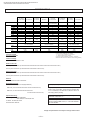
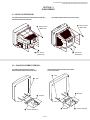
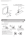
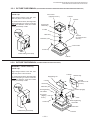
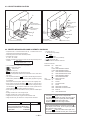
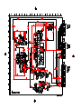
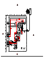
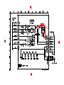
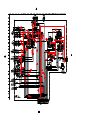
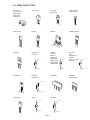
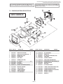
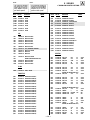
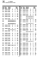
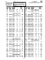
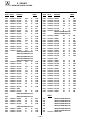
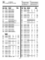
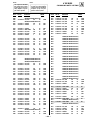
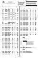
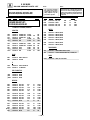
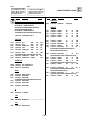
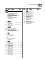
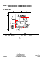
6-3. CIRCUIT BOARDS LOCATION
S MODELS
V MODELS
C
C
HS
B
(KV-32S45/32SL45/
35S40/35S45/37SL45)
WA
HS
(KV-35V65/37VL65/
37VL65C)
WA
(KV-32S40/34SL40/
34SL40C/32S45/34SL45)
HV
WB
WB
(KV-35S40/
35S45/37SL45)
(KV-32V40/34VL65C/
32V65/34VL65)
HV
(KV-35S40/32SL45/
35S45/37SL45)
G
P
G
(EXCEPT
KV-32V40)
A
A
UV
B
P
K
AV(EXCEPT KV-32V40)
(EXCEPT KV-32V40)
(KV-32S45/32SL45/35S45/37SL45)
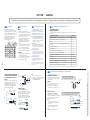
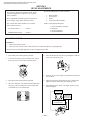
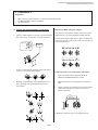
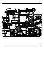
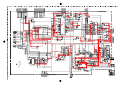
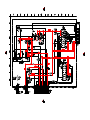
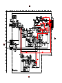
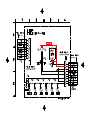
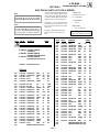
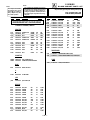
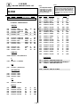
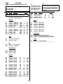
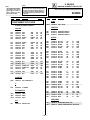
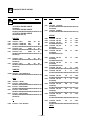
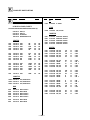
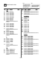
6-4. PRINTED WRING BOARDS AND SCHEMATIC DIAGRAMS
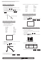
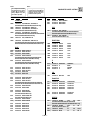
• All capacitors are in µF unless otherwise noted. pF : µµF 50WV or less are not
indicated except for electrolytics and tantalums.
• All electrolytics are in 50V unless otherwise specified.
• All voltages are in V.
S : Measurement impossibillity.
: B+line.
v : B-line.
•
•
• All resistors are in ohms.
KΩ=1000Ω, MΩ=1000kΩ
• Indication of resistance, which does not have one for rating electrical power, is
as follows.
Pitch : 5mm
•
(Actual measured value may be different).
: signal path. (RF)
• Circled numbers are waveform references.
Rating electrical power : 1/ 4 W
Reference information
RESISTOR : RN
METAL FILM
• 1/ 4 W in resistance, 1/10 W and 1/ 8 W in chip resistance.
•
: nonflammable resistor.
•
•
: RC
SOLID
: FPRD NONFLAMMABLE CARBON
: fusible resistor.
: internal component.
: FUSE NONFLAMMABLE FUSIBLE
: RW
NONFLAMMABLE WIREWOUND
: panel designation and adjustment for repair.
•
• All variable and adjustable resistors have characteristic curve B, unless otherwise noted.
• The components identified by
: RS
: RB
in this basic schematic diagram have been
carefully factory-selected for each set in order to satisfy regulations regarding
X-ray radiation.
Should replacement be required, replace only with the value originally used.
, make the necessary adjust• When replacing components identified by
ments indicated. If results do not meet the specified value, change the component identified by
and repeat the adjustment until the specified value is
achieved. (Refer to R530 and R531 adjustment on Page 15.)
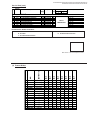
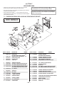
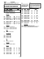
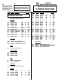
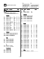
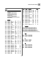
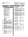
• When replacing the part in below table, be sure to perform the related adjustment.
• Readings are taken with a color-bar signal input.
• Readings are taken with a 10MΩ digital multimeter.
• Voltages are DC with respect to ground unless otherwise noted.
• Voltage variations may be noted due to normal production tolerances.
Part replaced( )
Adjustment(
IC351,IC501,D519,D520,D521
R530,R531
C531,C532,R387,R529,R530,R531,
R532,R533,R550,T503......A BOARD
IC643,R661.......................G BOARD
)
— 34 —
— 10 —
COIL
NONFLAMMABLE METAL OXIDE
NONFLAMMABLE CEMENT
ADJUSTMENT RESISTOR
:
: LF-8L MICRO INDUCTOR
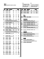
CAPACITOR : TA
: PS
TANTALUM
STYROL
: PP
: PT
POLYPROPYLENE
MYLAR
: MPS
: MPP
METALIZED POLYESTER
METALIZED POLYPROPYLENE
: ALB
: ALT
BIPOLAR
HIGH TEMPERATURE
The symbol
display is on the component side.
The components identified by shading and mark
are
critical for safety. Replace only with part number specified.
The symbol
indicate fast operating fuse.
Replace only with fuse of same rating as marked.
Les composants identifiés per un tramé et une marque
sont critiques pour la sécurité. Ne les remplacer que par une
piéce portant le numéro spécifié.
Le symbole
indique une fusible a action rapide. Doit
etre remplacee par une fusible de meme yaleur, comme maque.