1
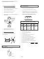
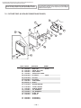
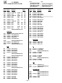
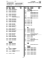
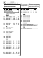
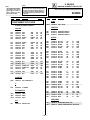
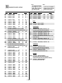
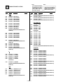
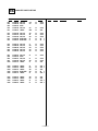
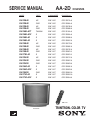
KV-32S40/32S45/34SL40/34SL40C/34SL40T/34SL45/35S40/35S45/37SL45/
32V40/32V65/34VL65/34VL65C/35V65/37VL65/37VL65C
SERVICE MANUAL
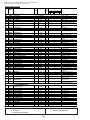
AA-2D
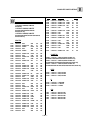
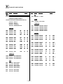
MODEL
DEST.
COMMANDER
CHASSIS NO.
KV-32S40
KV-32S40
KV-32S45
KV-32S45
KV-34SL40T
KV-34SL40C
KV-34SL40
KV-34SL45
KV-35S40
KV-35S40
KV-35S45
KV-35S45
KV-37SL45
KV-32V40
KV-32V40
KV-32V65
KV-34VL65
KV-34VL65C
KV-35V65
KV-37VL65
KV-37VL65C
US
RM-Y165
SCC-S07A-A
CND
RM-Y165
SCC-S08A-A
US
RM-Y165
SCC-S07B-A
CND
RM-Y165
SCC-S08B-A
TAIWAN
RM-Y165
SCC-S16A-A
E
RM-Y165
SCC-S09A-A
E
RM-Y165
SCC-S09B-A
E
RM-Y167
SCC-S09C-A
US
RM-Y165
SCC-S07D-A
CND
RM-Y165
SCC-S08E-A
US
RM-Y167
SCC-S07E-A
CND
RM-Y167
SCC-S08F-A
E
RM-Y167
SCC-S09F-A
US
RM-Y165
SCC-S07C-A
CND
RM-Y165
SCC-S08C-A
CND
RM-Y167
SCC-S08D-A
E
RM-Y167
SCC-S09E-A
E
RM-Y167
SCC-S09D-A
CND
RM-Y167
SCC-S08G-A
E
RM-Y167
SCC-S09G-A
E
RM-Y167
SCC-S09H-A
CHASSIS
RM-Y167
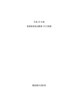
TRINITRON® COLOR TV
KV-35V65
—1—
KV-32S40/32S45/34SL40/34SL40C/34SL40T/34SL45/35S40/35S45/37SL45/
32V40/32V65/34VL65/34VL65C/35V65/37VL65/37VL65C
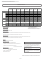
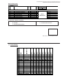
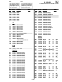
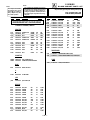
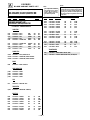
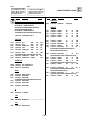
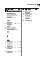
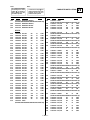
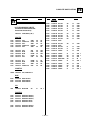
SPECIFICATIONS
KV-32S40
KV-34SL40/40T
KV-34SL40C
KV-32S45
KV-34SL45
KV-32V40
120V,60Hz
220V,50/60Hz
120V,60Hz
1
1
1
1
-
1
1
1
1
-
Speaker output(W)
5W x 2
Power Consumption(W)
In use(Max)
Power requirements
Number of inputs/outputs
Video 1)
S Video 2)
Audio 3)
Audio Out 4)
Monitor Out
TV out
S-Link
In standby
KV-32V65
KV-34VL65/65C
KV-35S40/45
KV-37SL45
KV-35V65
KV-37VL65
KV-37VL65C
120V,60Hz
120V,60Hz(65)
220V,50/60Hz(65C)
120V,60Hz
120V,60Hz
220V,50/60Hz
2
1
2
1
-
3
1
3
1
1
-
3
2
3
1
1
1
YES
2
1
2
1
-
3
2
3
1
1
1
YES
3
2
3
1
1
1
YES
5W x 2
5W x 2
5W x 2
10W x 2
5W x 2
10W x 2
10W x 2
180W
175W
180W
180W
200W(65), 195W(65C)
210W
230W
225W
2W
3W
2W
2W
2W(65), 3W(65C)
2W
2W
3W
Dimensions(W/H/D)
(mm)
(in)
791 x 707 x 604.5mm
821 x 675.3 x 587mm
870 x 761 x 653mm
920 x 730.8 x 641.8mm
31 x 27 13/16 x 23 3/4
32 3/8 x 26 5/8 x 23 1/8
34 1/4 x 30 x 25 5/8
36 1/4 x 28 3/4 x 25 1/4
Mass
(kg)
(lbs)
71.4kg
72.7kg
70kg
83kg
90kg
157lbs
160lbs
154lbs
183lbs
203lbs
1)
1 Vp-p 75 ohms unbalanced, sync negative
Y: 1 Vp-p 75 ohms unbalanced, sync negative
C: 0.286 Vp-p (Burst signal), 75 ohms
3)
500 mVrms (100% modulation), Impedance: 47 kilohms
4)
More than 408 mVrms at the maximum volume setting (variable)
2)
Television system
American TV standard
Channel coverage
VHF:2-13/UHF:14-69/CATV:1-125
Visible screen size
32-inch picture measured (KV-32S40/32S45/32V65/34SL40/34SL40C/34SL40T/34SL45/32V40/34VL65/34VL65C)
35-inch picture measured (KV-35S40/35S45/37SL45/35V65/37VL65/37VL65C)
Actual screen size
34-inch picture measured (KV-32S40/32S45/32V65/34SL40/34SL40C/34SL40T/34SL45/32V40/34VL65/34VL65C)
37-inch picture measured (KV-35S40/35S45/37SL45/35V65/37VL65/37VL65C)
Antenna
75 ohm external terminal for VHF/UHF
Supplied Accessories
Remote commander (w/2 size AA (R6) batteries)
(l ) SRS (SOUND RETRIEVAL SYSTEM)
RM-Y165: (KV-32S40/32S45/34SL40/34SL40T/34SL40C/35S40/32V40)
RM-Y167: (KV-34SL45/35S45/37SL45/32V65/34VL65/
34VL65C/35V65/37VL65/37VL65C)
The ( l ) SRS (SOUND RETRIEVAL SYSTEM) is manufactured by Sony Corporation under license from SRS Labs,
Inc. It is covered by U.S. Patent No. 4,748,669. Other U.S.
and foreign patents pending.
The word ‘SRS’ and the SRS symbol (l ) are registered
trademarks of SRS Labs, Inc.
Optional Accessory
Connecting Cables: VMC-810S/820S
VMC-720M,YC-15V/30V,RK-74A
TV-Stand: SU-32A3,SU-35A3
VHF/UHF Mixer: EAC-66
BBE and BBE symbol are trademarks of BBE Sound,Inc.
and are licensed by BBE Sound, Inc. under USP 4638258
and USP 4482866.
Design and specifications are subject to change without notice.
—2—
KV-32S40/32S45/34SL40/34SL40C/34SL40T/34SL45/35S40/35S45/37SL45/
32V40/32V65/34VL65/34VL65C/35V65/37VL65/37VL65C
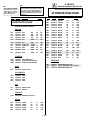
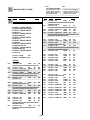
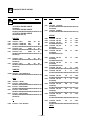
TABLE OF CONTENTS
Section
Title
Page
1. GENERAL
Connecting and Installing the TV .........................................
Operating Video Equipment...................................................
Operating a Cable Box or DBS Receiver...............................
Troubleshooting.....................................................................
5
7
8
8
2. DISASSEMBLY
2-1.Rear Cover Removal ......................................................
2-2.Chassis Assembly Removal ..........................................
2-3.Service Position .............................................................
2-4.Control Switch Removal ................................................
2-5-1. Picture Tube Removal (32"/34").................................
2-5-2. Picture Tube Removal (35"/37").................................
9
10
10
10
11
11
3. SET-UP ADJUSTMENTS
3-1.Beam Landing.................................................................
3-2.Convergence...................................................................
3-3.Focus...............................................................................
3-4.Screen (G2).....................................................................
3-5.White Balance Adjustments............................................
12
13
14
14
14
4. SAFETY RELATED ADJUSTMENTS ................................. 15
5. CIRCUIT ADJUSTMENTS .................................................... 16
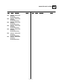
6. DIAGRAMS
6-1. S Series Block Diagram..................................................
6-2. V Series Block Diagrams ................................................
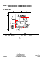
6-3. Circuit Boards Location...................................................
6-4.Printed Wiring Boards and Schematic Diagrams ............
23
27
34
34
Section
Title
• A Board......................................................................
• AV Board....................................................................
• B Board .....................................................................
• C Board ....................................................................
• G Board ....................................................................
• HV Board...................................................................
• HS Board ..................................................................
• K Board......................................................................
• P Board......................................................................
• WB Board..................................................................
• UV Board...................................................................
• WA Board...................................................................
6-5.Semiconductors..............................................................
Page
35
48
48
51
52
55
55
56
57
58
59
63
65
7. EXPLODED VlEWS
7-1. Chassis ......................................................................... 66
(KV-32S40/34SL40/34SL40C/32S45/34SL45/34SL40T)
7-2. Chassis.......................................................................... 67
(KV-35S40/35S45/37SL45)
7-3. Chassis.......................................................................... 68
(KV-32V40/32V65/34VL65/35VL65C/
35V65/37VL65/37VL65C)
7-3. Picture Tube .................................................................. 69
(KV-32V40/32V65/34VL65)
7-3. Picture Tube .................................................................. 70
(KV-35VL65C/35V65/37VL65/37VL65C)
8. ELECTRICAL PARTS LIST
• Table of Contents for Parts List.................................. 71
• Parts Listings............................................................. 72
WARNINGS AND CAUTIONS
ATTENTION
CAUTION!
AFTER REMOVING THE ANODE, SHORT CIRCUIT THE ANODE
OF THE PICTURE TUBE AND THE ANODE CAP TO THE METAL
CHASSIS, CRT SHIELD, OR CARBON PAINTED ON THE CRT.
APRES AVOIR DECONNECTE LE CAP DE L'ANODE, COURT-CIRCUITER L'ANODE
DU TUBE CATHODIQUE ET CELUI DE L'ANODE DU CAP AU CHASSIS METALLIQUE
DE L'APPAREIL, OU AU COUCHE DE CARBONE PEINTE SUR LE TUBE CATHODIQUE
OU AU BLINDAGE DU TUBE CATHODIQUE.
WARNING!!
ATTENTION!!
AN ISOLATION TRANSFORMER SHOULD BE USED DURING ANY
SERVICE TO AVOID POSSIBLE SHOCK HAZARD, BECAUSE OF
LIVE CHASSIS.THE CHASSIS OF THIS RECEIVER IS DIRECTLY
CONNECTED TO THE AC POWER LINE.
AFIN D'EVITER TOUT RESQUE D'ELECTROCUTION PROVENANT D'UN CHÁSSIS
SOUS TENSION, UN TRANSFORMATEUR D'ISOLEMENT DOIT ETRE UTILISÉ LORS
DE TOUT DÉPANNAGE. LE CHÁSSIS DE CE RÉCEPTEUR EST DIRECTEMENT
RACCORDÉ À L'ALIMENTATION SECTEUR.
SAFETY-RELATED COMPONENT WARNING!!
ATTENTION AUX COMPOSANTS RELATIFS A LA SECURITE!!
COMPONENTS IDENTIFIED BY SHADING AND MARK ¡ ON
THE SCHEMATIC DIAGRAMS, EXPLODED VIEWS AND IN THE
PARTS LIST ARE CRITICAL FOR SAFE OPERATION. REPLACE
THESE COMPONENTS WITH SONY PARTS WHOSE PART
NUMBERS APPEAR AS SHOWN IN THIS MANUAL OR IN
SUPPLEMENTS PUBLISHED BY SONY. CIRCUIT
ADJUSTMENTS THAT ARE CRITICAL FOR SAFE OPERATION
ARE IDENTIFIED IN THIS MANUAL. FOLLOW THESE
PROCEDURES WHENEVER CRITICAL COMPONENTS ARE
REPLACED OR IMPROPER OPERATION IS SUSPECTED.
LES COMPOSANTS IDENTIFIES PAR UNE TRAME ET PAR UNE MARQUE ¡ SUR
LES SCHEMAS DE PRINCIPE, LES VUES EXPLOSEES ET LES LISTES DE PIECES
SONT D'UNEIMPORTANCE CRITIQUE POUR LA SECURITE DU FONCTIONNEMENT.
NE LES REMPLACER QUE PAR DES COMPOSANTS SONY DONT LE NUMERO DE
PIECE EST INDIQUE DANS LE PRESENT MANUEL OU DANS DES SUPPLEMENTS
PUBLIES PAR SONY. LES REGLAGES DE CIRCUIT DONT L'IMPORTANCE EST CRITIQUE POUR LA SECURITE DU FONCTIONNEMENT SONT IDENTIFIES DANS LE
PRESENT MANUEL. SUIVRE CES PROCEDURES LORS DE CHAQUE
REMPLACEMENT DE COMPOSANTS CRITIQUES, OU LORSQU'UN MAUVAIS
FONTIONNEMENT SUSPECTE.
—3—
KV-32S40/32S45/34SL40/34SL40C/34SL40T/34SL45/35S40/35S45/37SL45/
32V40/32V65/34VL65/34VL65C/35V65/37VL65/37VL65C
SAFETY CHECK-OUT
After correcting the original service problem, perform the
following safety checks before releasing the set to the
customer:
1. Check the area of your repair for unsoldered or poorlysoldered connections. Check the entire board surface
for solder splashes and bridges.
2. Check the interboard wiring to ensure that no wires
are “pinched” or contact high-wattage resistors.
3. Check that all control knobs, shields, covers, ground
straps, and mounting hardware have been replaced.
Be absolutely certain that you have replaced all the
insulators.
4. Look for unauthorized replacement parts, particularly
transistors, that were installed during a previous
repair. Point them out to the customer and
recommend their replacement.
5. Look for parts which, though functioning, show
obvious signs of deterioration. Point them out to
the customer and recommend their replacement.
6. Check the line cords for cracks and abrasion.
Recommend the replacement of any such line cord
to the customer.
7. Check the B+ and HV to see if they are specified
values. Make sure your instruments are accurate;
be suspicious of your HV meter if sets always have
low HV.
8. Check the antenna terminals, metal trim, “metallized"
knobs, screws, and all other exposed metal parts for
AC Leakage. Check leakage as described below.
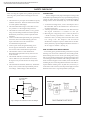
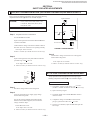
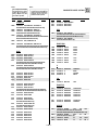
LEAKAGE TEST
The AC leakage from any exposed metal part to earth ground
and from all exposed metal parts to any exposed metal part having
a return to chassis, must not exceed 0.5 mA (500 microampere).
Leakage current can be measured by any one of three methods.
1. A commercial leakage tester, such as the Simpson 229 or
RCA WT-540A. Follow the manufacturers' instructions to
use these instructions.
2. A battery-operated AC milliammeter. The Data Precision
245 digital multimeter is suitable for this job.
3. Measuring the voltage drop across a resistor by means of
a VOM or battery-operated AC voltmeter. The "limit"
indication is 0.75 V, so analog meters must have an accurate
low voltage scale. The Simpson's 250 and Sanwa
SH-63Trd are examples of passive VOMs that are suitable.
Nearly all battery operated digital multimeters that have a
2V AC range are suitable. (See Fig. A)
HOW TO FIND A GOOD EARTH GROUND
A cold-water pipe is guaranteed earth ground; the cover-plate
retaining screw on most AC outlet boxes is also at earth ground.
If the retaining screw is to be used as your earth-ground, verify
that it is at ground by measuring the resistance between it and a
cold-water pipe with an ohmmeter. The reading should be zero
ohms. If a cold-water pipe is not accessible, connect a 60-l00 watts
trouble light (not a neon lamp) between the hot side of the receptacle and the retaining screw. Try both slots, if necessary, to
locate the hot side of the line, the lamp should light at normal
brilliance if the screw is at ground potential. (See Fig. B)
To Exposed Metal
Parts on Set
0.15 µF
1.5 k Ω
AC
Voltmeter
(0.75 V)
Earth Ground
Fig. A. Using an AC voltmeter to check AC leakage.
—4—
SECTION 1
GENERAL
The instructions mentioned here are partial abstracts from the Operating Instruction Manual. The page numbers shown reflect those of the Operating Instruction Manual.
Welcome!
Precautions
Thank you for purchasing the Sony
Trinitron® Color TV. This manual is written
for the models listed below. Before reading,
check the model number located on the front
of this manual or on the rear of your TV.
FAV
O
with RITE CH
Prev ANN
EL
iew
AUT
O
Con VOLUM
trol
E
SUR
ROU
ND
Model
Number
Sing
le
(VC tuner
R re
quir
ed fo
Dua
r PIP
l tu
)
("R ner
ead
y to
Use
" PIP
SRS
)
Model KV-35S45 is used for menu and
illustration purposes. Differences in
operation are indicated in the text; for
example, “KV-35S45 only”.
KV-32S40
KV-32S45
KV-32S65
KV-32V40
KV-32V65
KV-35S40
KV-35S45
KV-35S65
KV-35V65
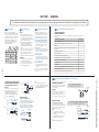
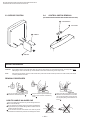
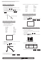
Connecting and Installing the TV
Using This Manual
Safety
• Operate the TV only with 120 V AC .
• The plug is designed, for safety purposes,
to fit in the wall outlet only one way. If
you are unable to insert the plug fully into
the outlet, contact your dealer.
• If any liquid or solid object should fall
inside the cabinet, unplug the TV
immediately and have it checked by
qualified personnel before operating it
further.
• If you will not be using the TV for several
days, disconnect power by pulling the
plug itself. Never pull on the cord.
For details concerning safety precautions, see the
supplied leaflet “IMPORTANT SAFEGUARDS”.
Installing
• To prevent internal heat build-up, do not
block the ventilation openings.
• Do not install the TV in a hot or humid
place, or in a place subject to excessive
dust or mechanical vibration.
This manual is divided into four major
sections. We recommend that you carefully
review the contents of each section in the
order presented to ensure that you fully
understand the operation of your new TV.
Making Connections
Refer to the table below, it will direct you to the diagram suitable to the components you will be
connecting.
If you will be connecting
1 Connecting and Installing the TV
This section guides you through your
initial set up. It shows how to connect to
your antenna or cable, and connect any
accessories or components.
2 Basic Set Up
This section teaches you the basic skills
needed to operate your new TV. It shows
you how to operate special functions of
the remote control.
3 Using your New TV
This section shows you how to begin
using your new TV. It shows how to use
the Easy Set Up Guide feature, and how to
use your remote control.
4 Using your Menus
This section teaches you how to access
on-screen menus and adjust your TV's
settings.
—5—
Instructions in this manual are written for the
remote control. Similar controls may be found on
the TV console.
See page
Cable or antenna only
5
Cable and antenna (KV-32S65, 32V65, 35S65, 35V65 only)
5
Cable box
6
Cable box and cable to view scrambled channels (KV-32S65, 32V65, 35S65,
35V65 only)
6
VCR and cable or antenna
7
VCR and cable box
7
Direct Broadcast Satellite Receiver (DBS)
8
VCR and Direct Broadcast Satellite Receiver (DBS)
8
Digital Versatile Disc player (DVD)
9
Audio system
9
A/V receiver
10
Two VCR's for tape editing (KV-32V40, 32V65, 35V65 only)
10
Camcorder to view tapes
11
S-Link connections (KV-32S65, 32V65, 35S65, 35V65 only)
12
4
3
Cable or Antenna Connections
Connecting directly to cable or an
antenna
The connection you choose will depend on the
cable found in your home. Newer homes will
be equipped with standard coaxial cable
(see A ); older homes will probably have
300 -ohm twin lead cable (see B ); still other
homes may contain both (see C ).
75-ohm coaxial cable
C
• VHF
(Rear of TV)
VHF/UHF
and
• In order to receive channels with an
antenna, you will need to turn your CABLE
to OFF (see page 26) and perform the
AUTO PROGRAM function.
Cable box
EAC-66 U/V mixer
(not supplied)
• UHF
Cable Box Connections
Some pay cable TV systems use scrambled or
encoded signals that require a cable box to
view all channels.
If you will be controlling all channel selection
through your cable box, you should consider using
the CHANNEL FIX feature discussed on page 26.
(Rear of TV)
VHF/UHF
Cable
1 Connect the coaxial connector from your
cable to the IN on your cable box.
300-ohm twin lead cable
2 Using a coaxial cable, connect OUT on
your cable box to VHF/UHF on your TV.
Cable and antenna
IN
OUT
Cable box
• KV-32S65, 32V65, 35S65, 35V65 only
A
• VHF only
or
• VHF/UHF
or
• Cable
B
• VHF only
or
• UHF only
or
• VHF/UHF
75-ohm
(Rear of TV)
coaxial cable VHF/UHF
300-ohm twin
lead cable
(Rear of TV)
VHF/UHF
If your cable provider does not feature local
channels, you may find this set up convenient
for viewing both local and cable channels.
• KV-32S65, 32V65, 35S65, 35V65 only
For this set up, you can switch between
scrambled channels (through your cable box),
and normal (CATV) channels by pressing
ANT on your remote control.
Select cable or antenna mode by pressing
ANT on the remote control. You will be able
to alternate between the two input sources.
CATV cable
Antenna connector
Cable box and cable
(No connection "TO
CONVERTER" in this case)
Notes
(Rear of TV)
AUX
• Your Sony remote control can be
programmed to operate your cable box.
(see page 32)
• When using PIP, you cannot view the
AUX input in the window picture.
TO CONVERTER
Antenna cable
Tip z
Pressing ANT switches between these inputs.
VHF/UHF
5
6
If you are connecting a cable box through the AUX input and would
like to switch between the AUX and normal (CATV) input you should
consider using the CHANNEL FIX feature discussed on page 26.
Cable box
(Rear of TV)
AUX
scrambled
channels
TO CONVERTER
75-ohm coaxial
cable (not supplied)
CATV cable
(unscrambled channels)
(signal)
VHF/UHF
KV-32S40/32S45/34SL40/34SL40C/34SL40T/34SL45/35S40/35S45/37SL45/
32V40/32V65/34VL65/34VL65C/35V65/37VL65/37VL65C
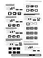
Connecting and Installing the TV (continued)
Note
VCR Connections
Connecting an antenna/cable TV
system with a VCR
1
2
3
1
You will need a splitter (not supplied) for the
following connection.
1 Connect the single (input) jack of the splitter
to your incoming cable connection. Connect
the other two (output) jacks (using coaxial
cable) to IN on your cable box and VHF/UHF
on your TV.
2 Using a coaxial connector, connect OUT on
your cable box to IN on your VCR.
3 Using A/V connectors, connect AUDIO and
VIDEO OUT on your VCR to AUDIO and
VIDEO IN on your TV.
AUDIO OUT
(VAR/FIX)
1 Connect the cable from your satellite
3
2
VHF/UHF
VIDEO
VCR
L
L
(MONO)
2
AUDIO
1
Cable
OUT
AUDIO R AUDIO L VIDEO
R
S VIDEO
R
LINE
OUT
IN
AUDIO-R (red)
AUDIO-L (white)
VIDEO (yellow)
2
* If you are connecting a monaural VCR, connect only the
single white audio output to the left input on your TV.
Connecting a VCR and TV with a
cable box
S VIDEO
Connecting a DBS (Direct
Broadcast Satellite) receiver
VIDEO IN
Coaxial cable
Attach the coaxial connector from your cable
or antenna to IN on your VCR.
Using A/V connectors, connect AUDIO and
VIDEO OUT on your VCR to AUDIO and
VIDEO IN on your TV.*
Using a coaxial connector, connect OUT on
your VCR to VHF/UHF on your TV.
Disconnect all power sources before making any connections.
DBS Connections
(Rear of TV)
VCR must be connected and
turned on to operate PIP
(KV-32S45, 35S45 only).
3
VMC-810S/820S (not supplied)
For optimum picture quality, use S VIDEO instead of
the yellow A/V cable. S Video does not provide sound,
your audio connectors must still be connected.
antenna to your DBS receiver.
2
S VIDEO
VHF/UHF
AUDIO OUT
(VAR/FIX)
VIDEO
L
VCR
OUT
IN
AUDIO R AUDIO L VIDEO
Cable
R
R
IN
4
AUDIO-R (red)
AUDIO-L (white)
VIDEO (yellow)
3
OUT
—6—
Splitter
(not supplied)
AUDIO
LINE
OUT
2
1
3
L
(MONO)
S VIDEO
1
5
VMC-810S/820S (not supplied)
Cable box
cable or antenna to VHF/UHF IN on your
VCR.
Using a coaxial connector, connect
VHF/UHF OUT on your VCR to
VHF/UHF on your TV.
Using A/V connectors, connect AUDIO
and VIDEO OUT on your DBS receiver to
AUDIO and VIDEO IN on your VCR.
Using A/V connectors, connect AUDIO
and VIDEO OUT on your VCR to AUDIO
and VIDEO IN on your TV.
2
S VIDEO
AUDIO OUT
(VAR/FIX)
DBS receiver
1
VIDEO
L
SATELLITE IN
AUDIO R AUDIO L VIDEO
Satellite
antenna
cable
AUDIO
IN
S VIDEO
L
(MONO)
VHF/UHF
R
R
OUT
LINE OUT
AUDIO-R (red)
AUDIO-L (white)
VIDEO (yellow)
3
VMC-810S/820S (not supplied)
4
1
Cable/Antenna
VMC-810S/820S (not supplied)
(Rear of TV)
2 Attach the coaxial connector from your
VIDEO IN
1
VIDEO IN
VHF/UHF
antenna to your DBS receiver.
Attach the coaxial connector from your
cable or antenna to VHF/UHF on your TV.
Using A/V connectors, connect AUDIO
and VIDEO OUT on your DBS receiver to
AUDIO and VIDEO IN on your TV.
1 Connect the cable from your satellite
(Rear of TV)
2
Connecting a DBS (Direct Broadcast
Satellite) receiver and a VCR
(Rear of TV)
Coaxial cable
Cable/Antenna
For optimum picture quality, use S VIDEO
instead of the yellow A/V cable. S Video does
not provide sound, your audio connectors
must still be connected.
VIDEO IN
1
SATELLITE IN
VHF/UHF
AUDIO OUT
(VAR/FIX)
VHF/UHF
AUDIO R AUDIO L VIDEO
S VIDEO
OUT
L
L
(MONO)
VHF/UHF
LINE IN
LINE OUT
VIDEO
2
S VIDEO
AUDIO R AUDIO L VIDEO
IN
AUDIO
IN
DBS receiver
2
S VIDEO
VCR
R
R
OUT
LINE OUT
AUDIO-R (red)
AUDIO-L (white)
VIDEO (yellow)
3
Pressing TV/VIDEO on the remote
control will allow you to view from
the DBS or VCR.
5
VMC-810S/820S (not supplied)
8
7
Connecting and Installing the TV (continued)
Disconnect all power sources before making any connections.
Additional Connections
The following connections are for accessories
that will enhance your viewing options.
(Rear of TV)
For optimum picture quality, use S VIDEO
instead of the yellow A/V cable. S Video
does not provide sound, your audio
connectors must still be connected.
1 Using A/V cables, connect TV OUT on your
2
2
S VIDEO
VHF/UHF
Connecting a DVD Player
AUDIO OUT
(VAR/FIX)
VIDEO
1 Using A/V connectors, connect LINE OUT
(Rear of DVD player)
L
L
(MONO)
on your DVD to VIDEO IN on your TV.
LINE OUT
AUDIO R AUDIO L VIDEO
AUDIO
TV to TV IN on your A/V receiver.
Using a single video connector, connect
Monitor OUT on your A/V receiver to
VIDEO 1 IN on your TV.
VIDEO 1 VIDEO 3
S VIDEO
2
OUT on your TV to one of the unused line
inputs (e.g. TV, AUX, TAPE 2) on your
stereo.
Set your stereo to the chosen line input.
Refer to page 24 of this manual for
additional audio setup instructions.
AUDIO
• KV-32V40, 32V65, 35V65 only
MONITOR OUT gives you the ability to use a
second VCR to record a program being played
by the primary VCR or to perform tape
editing and dubbing.
1 Connect the VCR intended for playback
using the setup instructions on page 7 of
this manual.
2 Using A/V connectors, connect AUDIO
and VIDEO IN on your VCR intended for
recording to MONITOR AUDIO and
VIDEO OUT on your TV.
2
S VIDEO
AUDIO OUT
(VAR/FIX)
VIDEO
1
AUDIO-L (white)
L
RK-74A
(not supplied)
(MONO)
AUDIO
R
AUDIO-R (red)
Line
input
2
A/V receiver
R
HRD
S-LINK
A/V inputs
1
VIDEO IN
VHF/UHF
AUDIO
(VAR/FIX)
VIDEO (yellow)
AUDIO-L (white)
AUDIO-R (red)
Connecting two VCRs
1 Using AUDIO connectors, connect AUDIO
MONITOR
(MONO)
(Rear of TV)
1
A/V outputs
OUT
TV
VIDEO
VMC-810S/820S (not supplied)
For enhanced sound, connect your audio
system to your TV.
(Rear of KV-35V65)
IN
Tip z
You may want to use CHANNEL FIX to set your TV's
input to the A/V receiver. See page 26.
R
AUDIO-R (red)
AUDIO-L (white)
VIDEO (yellow)
1
Connecting an audio system
VMC-10HG/30HG (not supplied)
VIDEO (yellow)
L
R
S VIDEO
2
• KV-32V65, 35V65 only
VIDEO IN
1
Disconnect all power sources before making any connections.
Connecting an A/V receiver
HRD
You cannot change video
inputs while editing using
MONITOR OUT.
VMC-810S/820S (not supplied)
(Rear of KV-35V65)
IN
VIDEO 1 VIDEO 3
S VIDEO
10
MONITOR
AUDIO
(VAR/FIX)
L
(MONO)
AUDIO
VCR (for playback)
AUDIO R AUDIO L VIDEO
R
VCR (for recording)
S-LINK
AUDIO R AUDIO L VIDEO
OUT
LINE
OUT
OUT
LINE
IN
IN
1
2
VMC-810S/820S (not supplied)
9
OUT
TV
VIDEO
IN
VIDEO (yellow)
AUDIO-L (white)
AUDIO-R (red)
VMC-810S/820S (not supplied)
KV-32S40/32S45/34SL40/34SL40C/34SL40T/34SL45/35S40/35S45/37SL45/
32V40/32V65/34VL65/34VL65C/35V65/37VL65/37VL65C
Connecting and Installing the TV (continued)
Disconnect all power sources before making any connections.
Connecting and Installing the TV (continued)
Disconnect all power sources before making any connections.
Connecting a camcorder
This connection is convenient for viewing a
picture directly from your camcorder.
Using A/V connectors, connect AUDIO and
VIDEO OUT on your camcorder to AUDIO
and VIDEO IN on your TV.
Connect to the CONTROL
S-IN on your VCR.
• KV-32S65, 32V65, 35S65, 35V65 only
S-Link is designed to allow your Sony
components to ”communicate“.
(Front of KV-32V40*, 32V65, 35V65 only)
S VIDEO
Connection can also be made directly to your
A/V input located on the rear of your TV.
VIDEO (yellow)
Note
AV output
VMC-810S/820S
(not supplied)
(Rear of KV-35V65)
VCR
IN
VIDEO 1 VIDEO 3
CONTROL S
IN OUT
LINE
OUT
S-LINK
S VIDEO
OUT
TV
MONITOR
AUDIO
(VAR/FIX)
VIDEO
L
(MONO)
RK-G69HG
(not supplied)
AUDIO
2
S-LINK
R
The S-Link connector must be in the
same VIDEO-IN jacks as the A/V cables
on your TV.
* KV-32V40 does not have S VIDEO on the front panel.
Connecting S-Link to a DBS
S-Link will automatically power on the TV
and switch to the correct video input when
you power on the DBS.
1 Using A/V connectors, connect AUDIO
and VIDEO OUT on your DBS to AUDIO
and VIDEO IN on your TV.
2 Using an S-Link connector (mono mini
plug), connect S-LINK on your DBS to
S-LINK on your TV.
—7—
11
VMC-810S/820S
(not supplied)
AUDIO R AUDIO L VIDEO
S-Link will automatically power on the TV
and switch to the correct video input when a
tape is inserted in the VCR.
1 Using A/V connectors, connect AUDIO
and VIDEO OUT on your VCR to AUDIO
and VIDEO IN on your TV.
2 Using an S-Link connector (mono mini
plug), connect S-LINK/CONTROL S-IN on
your VCR to S-LINK on your TV.
AUDIO-R (red)
AUDIO-L (white)
1
AUDIO-R (red)
AUDIO-L (white)
VIDEO (yellow)
Connecting S-Link to a VCR
VIDEO 2 INPUT
VIDEO L(MONO)-AUDIO-R
VIDEO L(MONO)-AUDIO-R
VIDEO 2 INPUT
• If you are connecting a monaural camcorder,
connect only the single white audio output
to the left input on your TV.
Disconnect all power sources before making any connections.
S-Link connections
If you have an S VIDEO equipped
camcorder, you can use an S Video
cable for optimum picture quality.
(Rear of KV-35V65)
DBS Receiver
SATELLITE IN
Satellite
Antenna
Cable
2
IN
AUDIO R AUDIO L VIDEO
VIDEO 1 VIDEO 3
S-LINK
LINE
OUT
S VIDEO
AUDIO-R (red)
AUDIO-L (white)
VIDEO (yellow)
RK-G69HG
(not supplied)
1
OUT
TV
MONITOR
AUDIO
(VAR/FIX)
VIDEO
L
(MONO)
AUDIO
R
VMC-810S/820S (not supplied)
S-LINK
12
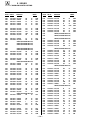
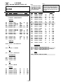
Programming the remote
You can use the supplied remote control to
operate Sony or non-Sony video equipment.
1
2
3
4
Press CODE SET.
Press VTR/DVD (FUNCTION).
Use the 0-9 buttons to key in the
manufacturer's code number from the
following chart.
Press ENTER.
VCR code numbers
Manufacturer
Sony
Admiral (M. Ward)
Aiwa
Audio Dynamic
Broksonic
Canon
Citizen
Craig
Criterion
Curtis Mathis
Daewoo
DBX
Dimensia
Emerson
Fisher
Funai
General Electric
Go Video
30
Code
301, 302, 303
327
338, 344
314, 337
319, 317
309, 308
332
302, 332
315
304, 338, 309
341, 312, 309
314, 336, 337
304
319, 320, 316, 317, 318, 341
330, 335
338
329, 304, 309
322, 339, 340
Goldstar
332
Hitachi
306, 304, 305,338
Instant Replay
309, 308
JC Penney
309, 305, 304, 330, 314, 336, 337
JVC
314, 336, 337, 345, 346, 347
Kenwood
314, 336, 332, 337
LXI (Sears)
332, 305, 330, 335, 338
Magnavox
308, 309, 310
Marantz
314, 336, 337
Marta
332
Memorex
309, 335
Minolta
305, 304
Mitsubishi/MGA
323, 324, 325, 326
Multitech
325, 338, 321
NEC
314, 336, 337
Olympic
309, 308
Optimus
327
Panasonic
308, 309, 306, 307
Pentax
305, 304
Philco
308, 309
Philips
308, 309, 310
Pioneer
308
Quasar
308, 309, 306
RCA/PROSCAN
304, 305, 308, 309, 311,
312, 313, 310, 329
Realistic
309, 330, 328, 335, 324, 338
Sansui
314
Samsung
322, 313, 321
Sanyo
330, 335
Scott
312, 313, 321, 335, 323, 324, 325, 326
Sharp
327, 328
Shintom
315
Signature 2000 (M. Ward)
338, 327
SV2000
338
Sylvania
308, 309, 338, 310
Symphonic
338
Tashiro
Tatung
Teac
Technics
Toshiba
Wards
Yamaha
Zenith
332
314, 336, 337
314. 336, 338, 337
309, 308
312, 311
327, 328, 335, 331, 332
314, 330, 336, 337
331
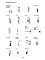
Operating a VCR
Buttons on the
remote control
To turn on or off
To select a channel
directly
To change
channels
To record
Press VTR/DVD (POWER).
Press the 0 – 9 buttons.
To play
To stop
To fast forward
To rewind the tape
To pause
To scan
To change input
mode
Press CH +/–.
Press ( and r
simultaneously.
Press (.
Press p.
Press ).
Press 0.
Press P.
To resume normal playback,
press again or press (.
Press ) or 0 during
playback.
To resume normal playback,
release the button.
Press TV/VTR.
Tips z
• In some rare cases, you may not be able to operate
your non-Sony video equipment with the supplied
remote control. In this case, please use the
equipment’s own remote control.
• When you remove the batteries, the code number may
revert to the factory setting.
• The code numbers for Sony VCR's are assigned at the
factory as follows:
VHS VCR
301
(preset code for the
supplied remote control)
8 mm VCR
302
Beta, ED Beta VCRs
303
DVD (Digital Versatile Disc)
code numbers
MDP (Multi Disc Player)
code numbers
Manufacturer
Sony
Panasonic
Pioneer
Code
701
704, 710
702
Manufacturer
Operating an MDP Buttons on the remote
control
To turn on or off
To play
To stop
To pause
To scan
To search the chapter
forward or backward
Tip
Press VTR/DVD (POWER).
Press (.
Press p.
Press P.
To resume normal playback,
press again or press (.
Press ) or 0 during
playback.
To resume normal playback,
press (.
Press CH +/–.
z
If you will not be programming a DBS or cable box into
the DBS/CABLE input, you can use it to program other
video equipment (e.g. DVD, MDP, or second VCR).
(see page 30)
Code
Sony
Panasonic
Pioneer
RCA
Toshiba
751
753
752
755
754
Operating a DVD
player
Buttons on the remote
control
To turn on or off
To play
To stop
To pause
Press VTR/DVD (POWER).
Press (.
Press p.
Press P.
To resume normal playback,
press again or press (.
Press ) or 0 during
playback.
To resume normal playback,
press (.
Press CH +/–.
To scan
To search the
chapter forward or
backward
To select chapters
directly
MENU
To move cursor in
menu
0–9 + ENTER.
Press to display DVD menu.
Use your arrow buttons
V, v, B, b.
31
KV-32S40/32S45/34SL40/34SL40C/34SL40T/34SL45/35S40/35S45/37SL45/
32V40/32V65/34VL65/34VL65C/35V65/37VL65/37VL65C
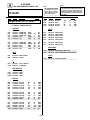
Operating Video Equipment
Troubleshooting
If the remote control doesn’t work
Cable box code numbers
You can program the supplied remote control
to operate a cable box or DBS receiver.
• First, try repeating the setup procedures
using the other codes listed for your
equipment.
Manufacturer
1
2
3
Press CODE SET.
Tips z
Press DBS/CABLE (FUNCTION).
• If more than one code number is listed, try entering
them one by one until you come to the correct code for
your equipment.
Programming the remote
4
Use the 0-9 buttons to key in the
manufacturer's code number from the
following chart.
Press ENTER.
For more details on operating the
cable box or DBS receiver
Refer to the operating instructions that were
supplied with the equipment.
• If you enter a new code number, the code number you
previously entered at that setting is erased.
• In some rare cases, you may not be able to operate
your equipment with the supplied remote control. In
this case, use the equipment’s supplied remote control.
• Whenever you remove the batteries the code numbers
may revert to the factory setting.
Hamlin/Regal
Jerrold/G. I.
Oak
Panasonic
Pioneer
Scientific Atlanta
Tocom
Zenith
Manufacturer
General Electric
Hitachi
Hughes
Panasonic
RCA/PROSCAN
Toshiba
—8—
Problem
Problem
What you can do
• VCR may not be connected to your TV properly.
• VCR may not be turned on.
• The remote control may not be programmed to
operate the VCR.
• Ensure that you have set your VCR correctly. (see page 7)
• Program your remote control to operate the VCR.
(see page 30)
A red light keeps flashing on the
TV for more than a few seconds
• Your TV may need service.
• Call your local Sony service center.
TV makes a noise when turned
on
• This is a normal function of your TV.
Screen is not lit and there is no
sound
• Power cord may not be plugged in.
• Batteries may not have been placed with the correct
polarity.
• TV/VIDEO setting may be incorrect.
• Press TV/VIDEO until you receive a channel.
Poor or no picture (screen lit),
good sound
• VIDEO menu settings may not be adjusted correctly.
• Antenna/cable connections may be faulty.
• VIDEO LABEL inputs may be set to WEB. (This label
darkens the screen for ideal WebTV viewing)
• Readjust your VIDEO menu settings.(see page 22)
• Check your VIDEO LABEL settings. (see page 28)
Good picture, no sound
• Sound may be set to MUTING.
• Your TV may be set to SAP.
• Speaker may not be set correctly.
• Press MUTE.
• Check the MTS setting in the AUDIO menu. (see page 23)
• Check your SPEAKER settings. (see page 23)
No color
• Color settings may not be adjusted correctly.
• Adjust the COLOR settings in the VIDEO menu.
(see page 22)
Code
801 (preset code for
remote control)
802
805
804
803
802, 808
806, 807
What it could be
Cannot operate single tuner PIP
(KV-32S45, 35S45)
33
What it could be
What you can do
Only snow and noise
appear on the screen
• CABLE may not be set correctly
in the SET UP menu.
• Antenna/cable connections may
not be correct.
• TV may be set to AUX mode.
Cannot receive upper
channels (UHF) when
using an antenna
• CABLE setting may not be correct • Ensure that CABLE is set to OFF
in the SET UP menu.
in the SET UP menu. (see page 26)
• Use AUTO PROGRAM to add
receivable channels that are not
presently in TV memory. (see
page 26)
Cannot receive any
channels when using
cable
• CABLE setting may not be set
correctly in the SET UP menu.
• Ensure that CABLE is set to ON
in the SET UP menu. (see page 26)
• Use AUTO PROGRAM to add
receivable channels that are not
presently in TV memory. (see
page 26)
Cannot gain enough
volume when using a
cable box
• Volume may not be adjusted on
your cable box.
• Press TV (FUNCTION) and
adjust the TV's volume.
TV is fixed to one
channel
• CHANNEL FIX settings may not
be correct.
• Check your CHANNEL FIX
settings. (see page 26)
• Ensure that you have selected the
correct CABLE mode in the
SET UP menu. (see page 26)
• Press ANT on your remote
control to change the input mode.
(see page 16)
If, after reading these operating instructions, you have additional questions related to the use of your Sony
television, please call our Direct Response Center at 1-800-222-SONY (7669). (U.S. residents only)
34
Code
222, 223, 224, 225, 226
201, 202, 203, 204, 205, 206,
207, 208, 218
227, 228, 229
219, 220, 221
214, 215
209, 210, 211
216, 217
212, 213
DBS receiver code numbers
Sony
32
Consult the table below; it suggests solutions to specific problems.
KV-32S40/32S45/34SL40/34SL40C/34SL40T/34SL45/35S40/35S45/37SL45/
32V40/32V65/34VL65/34VL65C/35V65/37VL65/37VL65C
Operating a Cable Box or DBS Receiver
KV-32S40/32S45/34SL40/34SL40C/34SL40T/34SL45/35S40/35S45/37SL45/
32V40/32V65/34VL65/34VL65C/35V65/37VL65/37VL65C
SECTION 2
DISASSEMBLY
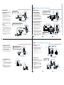
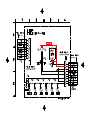
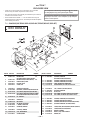
2-1. REAR COVER REMOVAL
(KV-32S40/34SL40/34SL40C/32S45/34SL45/34SL40T/
32V40/32V65/34VL65/34VL65C)
(KV-35S40/35S45/37SL45/37VL65/37VL65C)
1 Eleven Screws
(BVTP 4x16)
1 Eleven Screws
(BVTP 4x16)
2 Two Screws
(BVTP 3x12)
2 Two Screws
(BVTP 4x16)
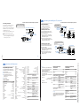
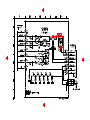
2-2. CHASSIS ASSEMBLY REMOVAL
(KV-32S40/34SL40/34SL40C/32S45/
34SL45/35S40/35S45/37SL45/34SL40T)
(KV-32V40/32V65/34VL65/34VL65C/35V65/
37VL65/37VL65C)
1 Claw
1 Claw
4 G Board
3 G Board
2 K Board
2 Chassis Assembly
—9—
3 Chassis Assembly
KV-32S40/32S45/34SL40/34SL40C/34SL40T/34SL45/35S40/35S45/37SL45/
32V40/32V65/34VL65/34VL65C/35V65/37VL65/37VL65C
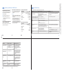
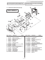
2-4.
2-3. SERVICE POSITION
CONTROL SWITCH REMOVAL
(KV-32V65/34VL65/34VL65C/35VL65/35VL65C/37VL65C)
1 Control Switch
2 Four Claws
2 G Board
1 A Board
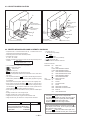
ANODE-CAP REMOVAL
WARNING:
High voltage remains in the CRT even after the power is disconnected. To avoid electrical shock, discharge CRT before
attempting to remove the anode cap. Short between anode and coated earth ground strap of CRT.
NOTE:
After removing the anode, short circuit the anode of the picture tube and the anode cap to either the metal chassis, CRT shield
or carbon painted on the CRT.
REMOVAL PROCEDURES
Turn up one side of the rubber cap in
the direction indicated by arrow .
Use your thumb to pull the rubber cap
firmly in the direction indicated by
arrow .
HOW TO HANDLE AN ANODE-CAP
Do not use sharp objects which may cause damage to the surface of the anode-cap.
Do not squeeze the rubber covering too hard to avoid damaging the anode-cap. A material fitting called a shatter-hook terminal is built into the rubber.
Do not force turn the foot of the rubber cover. This may cause
the shatter-hook terminal to protrude and damage the rubber.
— 10 —
When one side of the rubber cap separates from the anode button, the anodecap can be removed by turning the rubber cap and pulling it in the direction of
arrow .
KV-32S40/32S45/34SL40/34SL40C/34SL40T/34SL45/35S40/35S45/37SL45/
32V40/32V65/34VL65/34VL65C/35V65/37VL65/37VL65C
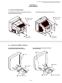
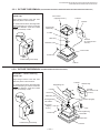
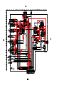
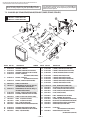
2-5-1. PICTURE TUBE REMOVAL (KV-32S40/34SL40/34SL40C/32S45/34SL45/34SL40T/32V40/32V65/34VL65/34VL65C)
WARNING -- Before removing
anode cap:
Four screws
(Tapping screw 7)
High voltage remains in the CRT even
after the power is disconnected.
To avoid electrical shock, discharge CRT
before attempting to remove the anode
cap. Short between anode and coated
earth ground strap of CRT.
G board
Chassis
Picture tube
shield assy
C board
Neck assy
K board
(KV-32V65/34VL65/
34VL65C)
Deflection yoke
Picture tube
Anode cap
Coated earth ground strap
Cushion
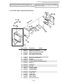
2-5-2. PICTURE TUBE REMOVAL (KV-35S40/35S45/37SL45/37VL65/37VL65C)
WARNING -- Before removing
anode cap:
High voltage remains in the CRT even
after the power is disconnected.
To avoid electrical shock, discharge CRT
before attempting to remove the anode
cap. Short between anode and coated
earth ground strap of CRT.
G board
Degaussing coil
Chassis assy
C board
K board
(KV-35V65/37VL65
/37VL65C)
Neck assy
Deflection yoke
Two Degaussing
coil holders
Tension spring(B)
Four screw
(Tapping
screw )
Anode cap
Claw
Two Degaussing
coil holders
Picture tube
Coated earth ground strap
Cushion
— 11 —
KV-32S40/32S45/34SL40/34SL40C/34SL40T/34SL45/35S40/35S45/37SL45/
32V40/32V65/34VL65/34VL65C/35V65/37VL65/37VL65C
SECTION 3
SET-UP ADJUSTMENTS
The following adjustments should be made when a
complete realignment is required or a new picture
tube is installed.
Perform the adjustments in order as follows:
1.
2.
3.
4.
These adjustments should be performed with rated
power supply voltage unless otherwise noted.
The controls and switch should be set as follows
unless otherwise noted:
Beam Landing
Convergence
Focus
Screen (G2)/White Balance
Note: Test Equipment Required
1.
2.
3.
4.
PICTURE control ................. normal
BRIGHTNESS control ......... normal
Color Bar Pattern Generator
Degausser
DC Power Supply
Digital Multimeter
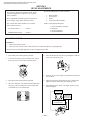
3-1. BEAM LANDING
Preparation:
•
•
Input a white pattern signal.
Face the picture tube in a East or West direction to reduce the influence of geomagnetism.
NOTE: Do not use the hand degausser because it magnetizes the CRT .
1.
Input white pattern from pattern generator.
2.
Loosen the deflection yoke mounting screw, and set
the purity control to the center as shown below:
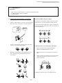
5.
Move the deflection yoke forward, and adjust so that the
entire screen becomes green.
6.
Switch over the raster signal to red and blue and confirm
the condition.
3.
Input green pattern from pattern generator.
7.
When the position of the deflection yoke is determined,
tighten it with the deflection yoke mounting screw.
4.
Move the deflection yoke backward, and adjust with
the purity control so that green is in the center and
red and blue are even on both sides.
8.
When landing at the corner is not right, adjust by using
the disk magnets.
Purity control
corrects this area.
B
R
G
b
a
c
d
Disk magnets or
rotatable disk
magnets correct
these areas(a-d).
Deflection yoke positioning
corrects these areas.
b
c
a
d
— 12 —
KV-32S40/32S45/34SL40/34SL40C/34SL40T/34SL45/35S40/35S45/37SL45/
32V40/32V65/34VL65/34VL65C/35V65/37VL65/37VL65C
3-2. CONVERGENCE
Preparation:
•
•
•
Before starting, perform FOCUS, V. LIN and V. SIZE adjustments.
Set BRIGHTNESS control to minimum.
Input dot pattern.
(1) Vertical and Horizontal Static Convergence
Operation of BMC (Hexapole) Magnet
1.
The respective dot positions resulting from moving each
magnet interact, so perform adjustment while tracking.
Adjust V. STAT magnet to converge red, green and blue
dots in the center of the screen. (Vertical movement)
Center dot
R
G
Use the VSTAT tabs to adjust the red, green, and blue dots
so they line up at the center of the screen (move the dots in
a horizontal direction.)
V.STAT
Magnet
B
Tilt the V. STAT magnet and adjust static convergence
to open or close the V. STAT magnet.
2.
When the V. STAT magnet is moved in the direction of
arrow a and b, red, green, and blue dots move as
shown below:
1
a
b
a
b
R G
B
R
G
B
R
R
B
R
G
B
R
G
G B
G
B
Y Separation Axis Correction Magnet Adjustment
1.
Input cross-hatch pattern, adjust PICTURE to
minimum and BRIGHTNESS to normal.
2.
Adjust the deflection yoke upright so it touches the
CRT.
3.
Adjust so that the Y separation axis correction magnet
on the neck assembly is symmetrical from top to
bottom (open state).
b
B
B
G
G
R
R
2
Purity
V. STAT
BMC (Hexapole)
a
a
R
G
B
b
b
B
G
R
4. Return the deflection yoke to its original position.
3
a
b
b
a
B
R
b
G
G
B
R
— 13 —
KV-32S40/32S45/34SL40/34SL40C/34SL40T/34SL45/35S40/35S45/37SL45/
32V40/32V65/34VL65/34VL65C/35V65/37VL65/37VL65C
( 2 ) Dynamic Convergence Adjustment
3-4. SCREEN (G2)
•
Before starting, perform Horizontal and Vertical
Static Convergence Adjustment.
1.
Input dot pattern from the pattern generator.
2.
Set the PICTURE and BRIGHT controls at normal.
1.
Slightly loosen deflection yoke screw.
3.
2.
Remove deflection yoke spacers.
Adjust S BRT, G CUT, B CUT in service mode with an
oscilloscope so that voltages on the red, green, and blue
cathodes are 170Vdc for 35"/37" and 180Vdc for 32"/34".
3.
Move the deflection yoke for best convergence as
shown below:
4.
Observe the screen and adjust SCREEN (G2) VR
to obtain the faintly visible background of dot signal.
N
N
R B GRB
G
G
B R GBR
GND
pedestal
N
170Vdc
170 V dc/
180 V dc
B G R R G B
R GB B GR
3-5. WHITE BALANCE ADJUSTMENTS
B R GBR
G
G
R B GRB
4.
5.
Tighten the deflection yoke screw.
Install the deflection yoke spacers.
NO.
Disp.
16
17
18
19
23
GDRV
BDRV
GCUT
BCUT
SBRT
Item
Green Drive
Blue Drive
Green Cut-off
Blue Cut-off
Sub Bright
Avg/32"
Avg/35"
33
33
3
2
14
45
45
6
6
10
(3) Screen-corner Convergence
1.
2.
Input an entire white signal.
Set to Service adjustment Mode.
Affix a permalloy assembly corresponding to the
misconverged areas:
3.
4.
Set DCOL to "0"
Set the PICTURE and BRIGHT to minimum.
5.
6.
Adjust with SBRT if necessary.
Select GCUT and BCUT with 1 and 4 .
7.
8.
Adjust with 3 and 6 for the best white balance.
Set the PICTURE and BRIGHT to maximum.
b
a
b
a
9. Select GDRV and BDRV with 1 and 4 .
10. Adjust with 3 and 6 for the best white balance.
a-d : screen-corner
misconvergence
c
d
d
c
11. Reset DCOL to "1".
12. Write into the memory by pressing
3-3. FOCUS
Adjust FOCUS control for best picture.
— 14 —
then
**.
KV-32S40/32S45/34SL40/34SL40C/34SL40T/34SL45/35S40/35S45/37SL45/
32V40/32V65/34VL65/34VL65C/35V65/37VL65/37VL65C
SECTION 4
SAFETY RELATED ADJUSTMENTS
R530, R531 CONFIRMATION METHOD (HOLD-DOWN CONFIRMATION) AND READJUSTMENTS
Always perform the following adjustments when replacing the following
components marked with a ] mark on the schematic diagram:
A BOARD:
IC351, IC501, D519, D520, D521, C531,
C532, R387, R529, R530, R531, R532,
R533, R550, T503
G BOARD:
IC643, R661
dejital
digital
multimeter
multimeter
+
-
R530
R531 R530
R531
Step 1
T503
T503
FBT
FBT
TP85
TP85
Preparation before Confirmation
11
Turn the POWER switch ON.
Input a white signal and set the PICTURE and BRIGHT
controls to maximum.
+
-
ammeter
ammeter
3mA DC
dc range
3mA
range
DC Power Supply
dc power supply
A
+
1T40 -
Confirm that the voltage at the check terminal of TP85 is
more than 18.0 V DC when the set is operating normally.
At AC input: 120.0 ± 2.0 VAC
A BOARD - CONDUCTOR SIDE
or 220.0 ± 2.0 VAC (for 34SL40C/34VL65C/37VL65C only)
Step 5
Confirm that a voltage of more than 18.0 V DC appears
between TP85 and ground.
Step 2
Input a white signal and verify that I ABL is within the
specified range: 2160 + 100 µA.
At AC input: 120.0 ± 2.0 VAC
or 220.0 ± 2.0 VAC (for 34SL40C/34VL65C/37VL65C only)
At AC input: 120.0 ± 2.0 VAC
or 220.0 ± 2.0 VAC (for 34SL40C/34VL65C/37VL65C only)
T504
FBT
B+ VOLTAGE CONFIRMATION AND ADJUSTMENT
ammeter
3.0 mA DC
range
ABL
+
A
Always perform the following adjustments when replacing the
following components marked with ] on the schematic diagram:
-
G BOARD: IC643, R661
I ABL
1) Using Variac, apply AC input voltage: 130 + 2.0 VAC
(or 220.0 ± 2.0 VAC for 34SL40C/34VL65C/37VL65C only)
Step 3
Record the voltage between TP85 and ground.
2) Input a monoscope signal.
Step 4
Using an external DC power supply, apply voltage
between TP85 and ground.
3) Set the PICTURE control and the BRIGHT control to
initial reset value.
Increase the voltage gradually and confirm that the
holdown works (raster disappears) at lower than the
voltage recorded in Step 3.
4) Confirm the voltage of G BOARD CN641 between
pin 1 to ground is less than 135.5 + 1.0 V DC.
5) If step 4 is not satisfied, replace the R661and repeat the
above steps.
Lower than 22.05 V DC
At AC input: 120.0 ± 2.0 VAC
or 220.0 ± 2.0 VAC (for 34SL40C/34VL65C/37VL65C only)
— 15 —
KV-32S40/32S45/34SL40/34SL40C/34SL40T/34SL45/35S40/35S45/37SL45/
32V40/32V65/34VL65/34VL65C/35V65/37VL65/37VL65C
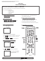
SECTION 5
CIRCUIT ADJUSTMENTS
ELECTRICAL ADJUSTMENT BY REMOTE COMMANDER
Use Remote Commander (RM-Y167) to perform the following circuit adjustments:
NOTE : Test Equipment Required:
1. Pattern Generator
2. Frequency Counter
3. Digital Multimeter
4. Audio OSC
(1) Method of Setting the Service
Adjustment Mode
8. Turn set off and on to exit. * CAUTION: Wait at least
10 seconds before turning off set.
(2) Memory Write Confirmation Method
SERVICE MODE PROCEDURE
1. Standby mode. (Power off)
2.
1. After adjustment, pull out the plug from the AC outlet,
then replace the plug in the AC outlet again.
2. Turn the power switch ON and set to Service Mode.
3. Call the adjusted items again to confirm they were adjusted.
on the
Remote Commander.
(Press each button within a second.)
SERVICE ADJUSTMENT MODE IN
Disp.
(Item)
SERVICE
(3) Adjust Buttons and Indicator
Item
data
AFC
0
3. The CRT displays the item being adjusted.
4. Press
5. Press
data.
or
or
6. Press
on the Remote Commander to select the item.
on the Remote Commander to change the
then
to write into memory**.
SERVICE ADJUSTMENT MODE MEMORY
SERVICE
RESET
Green
Red
7. Press then
initialize.
SERVICE
on the Remote Commander to
WRITE
Carry out step 7 when adjusting
IDs 0 to 4 and when replacing
and adjusting IC002.
RM-Y167
**WARNING: Do NOT turn off the power or AC immediately after pressing
— 16 —
then
. Wait at least 10 seconds.
KV-32S40/32S45/34SL40/34SL40C/34SL40T/34SL45/35S40/35S45/37SL45/
32V40/32V65/34VL65/34VL65C/35V65/37VL65/37VL65C
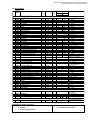
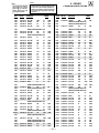
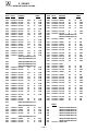
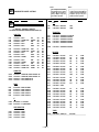
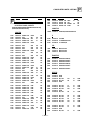
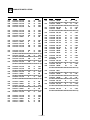
(4) Service Data
No.
Register
Name
Description
Data
Adj/Fix
Range
Initial
Average Data**
Data
32"
A
B
Comments
35"
C
D
E
VP CXA2095S
18
19
20
21
22
23
24
25
26
27
28
VPOS
VSIZ
VCOM
VLIN
VSCO
HPOS
HSIZ
PAMP
UPIN
LPIN
PPHA
AFC
VBOW
VANG
REF
GDRV
BDRV
GCUT
BCUT
SCON
SHUE
1SHU
SCOL
1SCO
SBRT
SSHP
1SSP
GMMA
V-Position
V-Size
V-Compensation
V-Linearity
S-Correction
H-Position
H-Size
Pin Compensation
Upper Corner Pin
Lower Corner Pin
Pin Phase
AFC
AFC Bow
AFC Angle
Reference Line
Green Drive
Blue Drive
Green Cutoff
Blue Cutoff
Sub Contrast
Sub Hue (RF only)
Sub Hue (composite & S-video)
Sub Color (RF only)
Sub Color (composite & S-video)
Sub Brightness
Sub Sharpness (RF & Composite video)
Sub Sharpness (S-video only)
Gamma Correction
0-63
0-63
0-3
0-15
0-15
0-15
0-63
0-63
0-15
0-15
0-15
0-3
0-15
0-15
0-3
0-63
0-63
0-15
0-15
0-15
0-15
0-15
0-15
0-15
0-63
0-15
0-15
0-3
Adj
Adj
Fix
Adj
Adj
Adj
Adj
Adj
Adj
Adj
Adj
Fix
Adj
Adj
Fix
Adj
Adj
Adj
Adj
Adj
Adj
Adj
Adj
Adj
Adj
Fix by model
Fix by model
Fix by model
20
20
1
7
7
7
20
31
7
7
7
2
7
7
2
31
31
7
7
7
7
7
7
7
31
7
7
1
29
CDM2
30
31
32
EYSW
DPIX
Y-DC
Countdown Mode 2
0-1
Fix
0
0
External Y Switch
Dynamic Picture
DC Transmission Ratio
0-1
0,1
0,1
Fix
Fix
Fix
0
1
1
0
1
1
33
ABLM
ABL Mode
0,1
Fix
1
1
34
35
36
37
38
39
40
41
42
43
44
45
46
47
48
49
50
AXIS
NOTC
CROM
TOT
1TOT
PREL
1PRE
SHPF
1SPF
RON
GON
BON
DCOL
CDMD
HBSW
LBLK
RBLK
Color Demodulation Axis
Chroma Trap Filter
Chroma Trap Adjust
TOT Filter (RF only)
TOT Filter (Composite & S-video)
Pre/Overshoot Ratio (RF & Composite)
Pre/Overshoot Ratio (S-video only)
Sharpness fo (RF & Composite)
Sharpness fo (S-video only)
Red Off
Green Off
Blue Off
Dynamic Color
V Countdown Mode
H Blanking Switch
Left Blanking
Right Blanking
0,1
0,1
0-15
0,1
0,1
0-3
0-3
0-3
0-3
0,1
0,1
0,1
0,1
0,1
0,1
0-15
0-15
Fix
Fix
Fix
Fix
Fix
Fix by model
Fix by model
Fix by model
Fix by model
Fix
Fix
Fix
Fix
Fix
Fix
Fix
Fix
1
0
7
1
1
3
3
2
2
1
1
1
0
0
0
0
0
1
0
7
1
0
1
3
1
3
1
1
1
1
0
0
7
7
51
SVOL
Sub Volume
0-15
Fix
0
6
52
53
SBAL
SBAS
STRE
Sub Balance
Sub Bass
Sub Treble
0-15
0-15
0-15
Adj
Fix by model
Fix by model
7
7
7
0,1
Fix
1
1
2
3
4
5
6
7
8
9
10
11
12
13
14
15
16
17
23
27
27
26
1
9
6
11
23
27
4
6
4
9
10
28
24
7
10
5
2
6
6
5
4
2
22
30
5
7
10
7 (flat-1)
7
11 (flat+2)
14
35
26
8
6
8
8 (flat-1)
7
9 (flat+2)
13
26
8
10
0
8
10
0
0:Down, 63:Up
0:Min, 63:Max
0:Min, 3:Max
0:Min, 15:Max
0:Min, 15:Max
0:Right, 15:Left
0:Min, 63:Max
0:Min, 63:Max
0:Min, 15:Max
0:Min, 15:Max
0:Min(small picture), 15:Max
0:Freerun, 1:Min, 3:Max
0:Right, 15:Left
0:Right, 15:Left
0:22H(Rch), 3:16H(Rch)
0:Min, 63:Max
0:Min, 63:Max
0:Min, 15:Max
0:Min, 15:Max
0:Min, 15:Max
0:+10deg, 15:-10deg
0:+10deg, 15:-10deg
0:Min, 15:Max
0:Min, 15:Max
0:Min, 63:Max
0:Min, 15:Max
0:Min, 15:Max
0:Off, 1:Min, 3:Max
0: Normal 1: High Speed
Countdown Response
0: Normal 1: EYin disabled
0:Off, 1:On
0:100%, 1:82%
0:PictureABL,
1:Picture/BrightnessABL
0:Japan, 1:US
0:Off, 1:On
0:+300kHz, 1:-300kHz
0:Off, 1:On
0:Off, 1:On
0: 2:1, 3: 5:1
0: 2:1, 3: 5:1
0:2.5MHz, 3:4.0MHz
0:2.5MHz, 3:4.0MHz
0:Off, 1:On
0:Off, 1:On
0:Off, 1:On
0:Off, 1:On
0:Auto, 1:Fix
0:Off, 1:On
0:Min, 15:Max
0:Min, 15:Max
AP CXA2021
54
7
10
7
8
10
10
7
0:-0 Volume steps, 15:-15
Volume steps
0: +Right, 15:+Left
8 0:-7 Steps, 15: +8 steps
10 0:-7 Steps, 15: +8 steps
MM1311/1313
55
AUSW
Audio Att Sw
**AVERAGE DATA MODEL GROUPINGS:
32"/34" A: KV-32S40/32S45/34SL40/34SL40C/34SL40T/34SL45
B: KV-32V40
C: KV-32V65/32VL65/34VL65C
0:-6dB, 1:0dB (Only for VIDEO
input)
1
35"/37" D: KV-35S40/35S45/37SL45
E: KV-35V65/37VL65/37VL65C
**WARNING: Do NOT turn off the power or AC immediately after pressing
— 17 —
then
. Wait at least 10 seconds.
KV-32S40/32S45/34SL40/34SL40C/34SL40T/34SL45/35S40/35S45/37SL45/
32V40/32V65/34VL65/34VL65C/35V65/37VL65/37VL65C
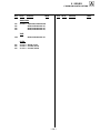
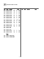
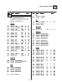
Service Data (cont.)
No.
Register
Name
Description
Data
Adj/Fix
Range
Initial
Average Data**
Data
32"
A
B
Comments
35"
C
D
E
PI SDA9288
56
57
58
59
60
PYSD
PIPH
PIPV
PYDL
PHDL
Select Delay
PIP H-position
PIP V-position
PIP Y-delay
H-pulse delay
0-15
0-127
0-63
0-7
0-15
Fix by P-bd
Fix
Fix
Fix
Fix by P-bd
3
78
18
0
3
3
78
18
0
0
61
PMVD
Main V-pulse delay
0-31
Fix
16
16
62
PIVD
Inset V-pulse delay
0-31
Fix
22
22
63
64
PCON
FRMY
Inset Contrast
Frame Y
0-15
0-15
Fix
Fix
7
7
7
7
0:Right, 15:Left
0:Right, 127:Left
0:Up, 63:Down
0:Right, 7:Left
0:Right, 15:Left
7-21: Available (1-6/22-31 Not
Avail)
16-28 Available (1-15/29-31 Not
Avail)
0:Min, 15:Max
0:Dark, 15:Bright
65
CHRI
Input Polarity
0,1
Fix by P-bd
1
1
0:+(B-Y)+(R-Y), 1:-(B-Y)-(R-Y)
66
CHRO
Output Polarity
0,1
Fix
1
1
0:+(B-Y)+(R-Y), 1:-(B-Y)-(R-Y)
67
68
IPER
IPEB
Inset Pedestal R-Y
Inset Pedestal B-Y
0-15
0-15
Fix
Fix
0
0
0
0
69
PCPS
CLPS Bit Control
0,1
Fix
0
0
70
71
73
PCPF
PSEL
PPLL
PVNR
CLPFIX Bit Control
SELDOWN Bit Control
PLL Filter Bits
VSPISQ VSP NR
0,1
0,1
0-3
0-1
Fix
Fix by P-bd
Fix
Fix
0
1
0
0
0
1
0
1
0:Center, 7:Max, 8:Min
0:Center, 7:Max, 8:Min
0:Depend on HSIDEL, 1:Not
depend
0: 3Clamp line, 1: 2Clamp line
0:Open out, 1:TTL out
Fixed value only
SDA9288 IC bypass use 1
74
75
76
77
78
79
80
81
82
83
84
85
86
87
88
89
ISCO
ISHP
ISCL
ISHU
ITOT
IAFC
ICD2
IYDR
IVPE
IUPE
IRVP
IRUP
IDCT
IRYD
IABO
IPRE
CDec Sub Contrast
CDec Sharpness
CDec Sub Color
CDec Sub Hue
CDec TOT on
CDec AFC
CDec Countdown Mode2
CDec Y drive
CDec V pedestal
CDec U pedestal
CDec RV pedestal
CDec RU pedestal
CDec DC transfer
CDec RY drive
CDec ABL off
CDec Pre/Over shoot
0-15
0-15
0-15
0-15
0,1
0-3
0,1
0-31
0-15
0-15
0-15
0-15
0-7
0-31
0,1
0-3
Fix
Fix
Fix
Fix
Fix
Fix
Fix
Fix
Fix
Fix
Fix
Fix
Fix
Fix
Fix
Fix
7
7
7
7
0
2
0
15
7
7
7
7
2
15
1
3
15
8
9
6
1
2
0
7
6
6
6
6
0
20
1
3
90
IRUD
CDec RU Drive
0-31
Fix
15
20
91
92
93
IABL
IABC
IRVD
CDec ABL
CDec ABL Cent
CDec RV drive
0,1
0-3
0-31
Fix
Fix
Fix
1
1
15
1
1
17
94
IDLY
CDec Delay
0-3
Fix
0
0
95
ISCR
CDec SCP BGR
0-3
Fix
0
0
96
ISCF
CDec SCP BGF
0-3
Fix
0
0
97
CRIL
CC CRI count low
0-15
Fix
2
2
98
99
100
101
102
103
104
105
106
107
108
109
CFLD
CCDI
CRIP
CRIT
CSB1
CSB2
CREP
CDSD
CCDS
CHMK
CHSY
DISP
RTCO
CC Caption Fixed Field Count
CC CCD int
CC CRI & polarity
CC CRI time constant
CC Sync Slice Bias 1
CC Synce Slice Bias 2
CC CRI signal end position
CC Data start delay
CC Caption data threshold
CC P8_HMASK
CC P8_HSYC
TV OSD H Position
Rotation Coil
0-7
0-7
0-3
0-3
0-7
0-255
0-31
0-31
0-63
0-255
0-63
0-63
Fix
Fix
Fix
Fix
Fix
Fix
Fix
Fix
Fix
Fix
Fix
Adj
Fix
5
3
4
1
3
4
142
8
9
42
136
1
32
5
3
4
1
3
4
142
8
9
42
136
23
32
72
IC CXA2019
PiP sub contrast
PiP sharpness
PiP sub color
PiP sub hue
PiP TOT 0:Off, 1:On
0:Max, 2:Min, 3:Freerun
0:Standard, 1:Fast
PiP Y-drive gain
PiP V-ped DC
PiP U-ped DC
PiP V-ped DC (re-input)
PiP U-ped DC (re-input)
PiP DC transfer 0:Max, 7:Min
PiP RY Drive (re-input)
PiP ABL (RY-OUT) 0:On, 1:Off
PiP Pre/over shoot 0: 1:1, 1: 4:1
PiP RU-gain out 0:-6dB,
31:+3.3bD
PiP ABL gain 0:Std, 1:Min
PiP ABL Center 0:Min, 1:Max
PiP RY Drive (re-input)
PiP Y-delay 0:0ns, 1:60ns,
2:120ns, 3:180ns
PiP SCP riseup phase 0:+0.4us,
1:cent, 2:-0.8us
PiP SCP falldown phase
0:+0.4us, 1:cent, 2:-0.8us
CC CXP8584a-011s
110
**AVERAGE DATA MODEL GROUPINGS:
32"/34" A: KV-32S40/32S45/34SL40/34SL40C/34SL40T/34SL45
B: KV-32V40
C: KV-32V65/32VL65/34VL65C
**WARNING: Do NOT turn off the power or AC immediately after pressing
7 Clock Run-In Lower Limit (field
1)
Fixed value only
Fixed value only
Fixed value only
Fixed value only
Fixed value only
Fixed value only
Fixed value only
Fixed value only
Fixed value only
Hmask
Hsyc
0:Off, 1:Left, 63: Right
Fixed value only
35"/37" D: KV-35S40/35S45/37SL45
E: KV-35V65/37VL65/37VL65C
— 18 —
then
. Wait at least 10 seconds.
KV-32S40/32S45/34SL40/34SL40C/34SL40T/34SL45/35S40/35S45/37SL45/
32V40/32V65/34VL65/34VL65C/35V65/37VL65/37VL65C
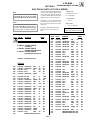
Service Data (cont.)
No.
Register
Name
Description
Data
Adj/Fix
Range
Initial
Average Data**
Data
32"
A
B
Comments
35"
C
D
E
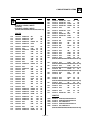
ID MAP
111
112
113
114
115
116
117
118
ID-0
ID-1
ID-2
ID-3
ID-4
ID-5
ID-6
ID-7
ID-0 (Language/Color Systems)
ID-1 (Input/Output Conifguration)
ID-2 (Audio)
ID-3 (OSD/Timer/V-chip/Ch Fix)
ID-4 (CC/Spot Killer/etc)
ID-5 (V-series Features/etc)
ID-6 (PiP/Ant Sw related)
ID-7 (Special Models/etc)
0-255
0-255
0-255
0-255
0-255
0-255
0-255
0-255
Fix by model
Fix by model
Fix by model
Fix by model
Fix by model
Fix by model
Fix by model
Fix by model
**AVERAGE DATA MODEL GROUPINGS:
32"/34" A: KV-32S40/32S45/34SL40/34SL40C/34SL40T/34SL45
B: KV-32V40
C: KV-32V65/32VL65/34VL65C
89
55
175
0
155
141
6
0
See
See
See
See
See
See
See
See
refer to
NVM ID Chart
ID
ID
ID
ID
ID
ID
ID
ID
map
map
map
map
map
map
map
map
35"/37" D: KV-35S40/35S45/37SL45
E: KV-35V65/37VL65/37VL65C
SERVICE
IDO
25
Note: Items 1-118 show adjustment order
DESTINATION
ID-0
ID-1
ID-2
ID-3
ID-4
ID-5
ID-6
ID-7
1
2
3
4
6
7
8
9
10
11
12
13
14
15
16
17
KV-
(5) Feature ID Map
32S40
32S45
32V40
32V65
35S40
35S45
35V65
34SL40C
34VL65C
37VL65C
34SL40
34SL45
34VL65
37SL45
37VL65
34SL40T
(US/CND)
(US/CND)
(US/CND)
(CND)
(US/CND)
(US/CND)
(CND)
(E)
(E)
(E)
(E)
(E)
(E)
(E)
(E)
(TAIWAN)
89
89
89
89
89
89
89
25
25
25
25
25
25
25
25
9
17
21
23
55
21
21
55
17
55
55
17
21
55
21
55
17
31
31
175
175
31
31
175
159
175
175
159
159
175
159
175
159
10
10
10
10
10
10
10
74
74
74
74
74
74
74
74
10
27
27
27
27
155
155
155
59
59
187
59
59
59
187
187
27
129
129
129
141
129
129
141
129
141
141
129
129
141
129
14
129
0
1
0
6
6
1
6
0
6
6
0
1
6
1
6
0
0
0
0
0
0
0
0
0
0
0
0
0
0
0
0
0
**WARNING: Do NOT turn off the power or AC immediately after pressing
— 19 —
then
. Wait at least 10 seconds.
KV-32S40/32S45/34SL40/34SL40C/34SL40T/34SL45/35S40/35S45/37SL45/
32V40/32V65/34VL65/34VL65C/35V65/37VL65/37VL65C
SUB BRIGHT ADJUSTMENT (SBRT)
10. Return the following back to normal after adjustment.
1. Set to Service adjustment Mode.
2. Input a gray scale pattern signal.
3. Set the PICTURE to minimum, and BRIGHT to normal.
4. Select SBRT with and .
5. Adjust SUB BRIGHT level with and
second from the right is faintly visible.
PICTURE . . . . . . . . . . . MAX
COLOR . . . . . . . . . . . CENTER
BRIGHT . . . . . . . . . . . CENTER
R ON
G ON
B ON
so that the stripe
6. Write into the memory by pressing
**.
then
. . . . . . . . . . . ON (1)
. . . . . . . . . . . ON (1)
. . . . . . . . . . . ON (1)
DISPLAY POSITION ADJUSTMENT (DISP)
white
1. Input a color-bar signal.
2. Set to Service adjustment Mode.
second from the right
3. Select DISP with and .
4. Adjust with and for adjustment of characters to center .
then
**.
5. Write the memory by pressing
black
SUB CONTRAST ADJUSTMENT (SCON)
SERVICE
1.
2.
3.
4.
AFC
0
Input a color-bar signal.
Set to Service adjustment Mode.
Select the item DCOL to "0" level.
Set the conditions as follows.
PICTURE . . . . . . . . . . .
COLOR . . . . . . . . . . .
BRIGHT . . . . . . . . . . .
MAX
MIN
CENTER
R ON
G ON
B ON
ON (1)
OFF (0)
OFF (0)
...........
...........
...........
SUB HUE, SUB COLOR ADJUSTMENT (SHUE, SCOL)
1. Input a color-bar signal.
2. Set to Service adjustment Mode.
3. Connect oscilloscope probe to C Board, CN1761 Pin3
(BLUE OUT).
4. Select SHUE and SCOL with and .
5. Adjust with and for the V1 = V4 ± 0.1Vp-p (SCOL)
and V2 = V3 ± 0.1Vp-p (SHUE).
1: ON
0: OFF
SERVICE
RON
1
V1
V2 V3
V4
5. Connect an oscilloscope probe to C Board, CN1761 pin 1
(RED OUT).
6. Change data according to the following table;
and .
for: 2.10 ± 0.01 Vp-p.
32"
35"
n
6. Select SCON with
7. Adjust with and
White
SCOL
SHUE
+2 steps
+2 steps
-1 steps
-1 steps
2.10 ± 0.1 Vp-p
n
7. Write into the memory by pressing
Black
8. Reset the item DCOL to "1" level.
9. Write the memory by pressing
then
** .
**WARNING: Do NOT turn off the power or AC immediately after pressing
— 20 —
then
. Wait at least 10 seconds.
then
**.
KV-32S40/32S45/34SL40/34SL40C/34SL40T/34SL45/35S40/35S45/37SL45/
32V40/32V65/34VL65/34VL65C/35V65/37VL65/37VL65C
PIN AMP (PAMP)
V. SIZE ADJUSTMENT ( VSIZ)
1. Input a cross-hatch signal.
2. Set to Service adjustment mode.
3. Select VSIZ with and .
4.Adjust with and for the best vertical size.
5.Write into the memory by pressing
then
PIN PHASE (PPHA)
**.
V. SIZE
/
/
V ANGLE (VANG), V BOW (VBOW), UPPER PIN (UPIN)
AND LOW PIN (LPIN) ADJUSTMENTS
1. Input a cross hatch signal.
2. Set to Service adjustment Mode.
V. POSITION ADJUSTMENT (VPOS)
1.Input a cross-hatch signal.
2.Set to Service adjustment Mode.
3. Select VVANG, VBOW, UPIN, and LPIN with
4. Adjust with and for the best picture.
5. Write the memory by Pressing
then
3.Select VPOS with and .
4.Adjust with and for the best vertical center.
5.Write into the memory by pressing
then
and
.
** .
V ANGLE (VANG)
**.
V. POSITION
V BOW (VBOW)
H. POSITION ADJUSTMENT (HPOS)
1. Input a cross-hatch signal.
2. Set the Service adjustment Mode.
UPPER PIN (UPIN)
3. Select HPOS with and .
4. Adjust with and for the best horizontal center.
5. Write into the memory by pressing
then
**.
H. POSITION
LOW PIN (LPIN)
V LINEARITY (VLIN), V CORRECTION (VSCO), PIN AMP
(PAMP) AND PIN PHASE (PPHA) ADJUSTMENTS
1. Input a cross-hatch signal.
2. Set to Service adjustment Mode.
3. Select VLIN, VSCO, PAMP, and PPHA with
4. Adjust with and for the best picture.
5. Write the memory by Pressing
then
V LINEARITY(VLIN)
VS CORRECTION (VSCO)
P BOARD ADJUSTMENTS
and
.
** .
PIP V. POSITION (PIPV), PIP H. POSITION (PIPH)
1. Input a color bar signal.
2. Set to service adjustment mode.
3. Select PHOP with and .
4. Adjust with and for the best balanced position at four
corner P in P display position.
5. Adjust P in P put at lower right position.
6. Write the memory by Pressing
**WARNING: Do NOT turn off the power or AC immediately after pressing
— 21 —
then
then
**.
. Wait at least 10 seconds.
6-3. CIRCUIT BOARDS LOCATION
S MODELS
V MODELS
C
C
HS
B
(KV-32S45/32SL45/
35S40/35S45/37SL45)
WA
HS
(KV-35V65/37VL65/
37VL65C)
WA
(KV-32S40/34SL40/
34SL40C/32S45/34SL45)
HV
WB
WB
(KV-35S40/
35S45/37SL45)
(KV-32V40/34VL65C/
32V65/34VL65)
HV
(KV-35S40/32SL45/
35S45/37SL45)
G
P
G
(EXCEPT
KV-32V40)
A
A
UV
B
P
K
AV(EXCEPT KV-32V40)
(EXCEPT KV-32V40)
(KV-32S45/32SL45/35S45/37SL45)
6-4. PRINTED WRING BOARDS AND SCHEMATIC DIAGRAMS
• All capacitors are in µF unless otherwise noted. pF : µµF 50WV or less are not
indicated except for electrolytics and tantalums.
• All electrolytics are in 50V unless otherwise specified.
• All voltages are in V.
S : Measurement impossibillity.
: B+line.
v : B-line.
•
•
• All resistors are in ohms.
KΩ=1000Ω, MΩ=1000kΩ
• Indication of resistance, which does not have one for rating electrical power, is
as follows.
Pitch : 5mm
•
(Actual measured value may be different).
: signal path. (RF)
• Circled numbers are waveform references.
Rating electrical power : 1/ 4 W
Reference information
RESISTOR : RN
METAL FILM
• 1/ 4 W in resistance, 1/10 W and 1/ 8 W in chip resistance.
•
: nonflammable resistor.
•
•
: RC
SOLID
: FPRD NONFLAMMABLE CARBON
: fusible resistor.
: internal component.
: FUSE NONFLAMMABLE FUSIBLE
: RW
NONFLAMMABLE WIREWOUND
: panel designation and adjustment for repair.
•
• All variable and adjustable resistors have characteristic curve B, unless otherwise noted.
• The components identified by
: RS
: RB
in this basic schematic diagram have been
carefully factory-selected for each set in order to satisfy regulations regarding
X-ray radiation.
Should replacement be required, replace only with the value originally used.
, make the necessary adjust• When replacing components identified by
ments indicated. If results do not meet the specified value, change the component identified by
and repeat the adjustment until the specified value is
achieved. (Refer to R530 and R531 adjustment on Page 15.)
• When replacing the part in below table, be sure to perform the related adjustment.
• Readings are taken with a color-bar signal input.
• Readings are taken with a 10MΩ digital multimeter.
• Voltages are DC with respect to ground unless otherwise noted.
• Voltage variations may be noted due to normal production tolerances.
Part repla