1
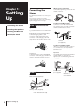
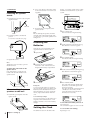
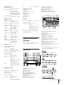
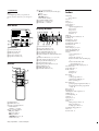
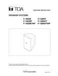
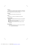
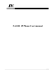
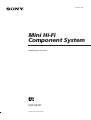
3-856-227-12(1)
Mini Hi-Fi
Component System
Operating Instructions
CHC-P33D
© 1996 by Sony Corporation
Chapter 1:
Setting
Up
Connecting the Stereo
AM loop aerial connection
Connect the supplied loop aerial to the AM
and the y terminals.
Connecting the
Stereo
Use the illustrations below to connect your
stereo.
If you want to connect any optional
components to the stereo, see “Connecting
Optional Equipment” in Chapter 6.
STEP 1 Connecting the
Speakers
Installing the Speakers
Inserting the Batteries
Setting the Clock
To improve the FM reception
Connect an outdoor FM aerial to the FM
75Ω terminal, using a 75-ohm coaxial cable
and IEC standard socket connector.
For speakers installation, see “Installing the
Speakers”.
Right (R) and Left (L) satellite speakers
Connect the right speaker to the R
connectors and the left speaker to the L
connectors. Connect the grey cords with
white stripes to ‘ and the solid grey cords
to ’.
FM
75Ω
AM
IEC standard socket
connector
(not supplied)
‘
R
‘
’
’
L
Superwoofer
Connect the superwoofer to the WOOFER
connectors. Connect the grey cord with red
stripes to ‘ and the solid grey cord to ’.
’
To improve the AM reception
After you connect the AM aerial, connect a
6- to 15-meter (20- to 50- feet) insulated
wire to the AM terminal. Connect the y
terminal to earth.
Important
Ground the external aerial from y terminal
against lightning. To prevent a gas
explosion, do not connect the ground wire
to a gas pipe.
‘
FM
75Ω
AM
STEP 2 Connecting the
Aerials
FM lead aerial (supplied)*
FM
75Ω
AM
AM loop aerial (supplied)
* Note: Extend horizontally
4
Chapter 1: Setting up
Insulated wires
(not supplied)
Ground wire
(not supplied)
Right satellite speaker
Superwoofer
AM loop aerial
Left satellite speaker
FM lead aerial
STEP 2
STEP 1
STEP 3
to a wall outlet
Do this connection last!
STEP 3 Connecting the
Power
Connect the mains lead to a wall outlet
after you have made all the above
connections.
Note
Do not install the woofer close to the unit,
and do not place the woofer above or below
the unit. Otherwise, the vibration from the
woofer may cause mechanical noise or
“skipping”.
When installing the speakers on
either side of the main unit
Place the woofer between the two satellite
speakers.
+
=
to a wall
outlet
When installing the satellite
speakers away from each other
Position the satellite speakers so they face
toward your listening position.
When installing the satellite
speakers away the woofer
1 Insert the supplied stand into the rear of
the woofer.
Installing the
Speakers
Proper speaker positioning is essential in
order to achieve directional effects and
diffused ambiance.
When you install the speakers, refer to the
following instructions.
Once you have determined the final
placement, fasten the speakers to the
speaker stands.
continue to next page ➔
2 Install the woofer between the satellite
speakers with its front panel facing
upward.
Chapter 1: Setting up
5
➔ continued
Fastening the speaker
stands
2 Use a screw driver to attach the stands
to the wall with four wood screws (not
supplied).
display. You need to set the clock to utilise
the timer-activated features of your stereo
system.
DISPLAY
1 Fasten the four screws loosely using the
supplied wrench.
Wrench
+
=
1
3,5
2,4
3 Re-attach the caps and plates to the
speaker stands.
Screw
2 Rotate the speaker to the desired
position.
You can also rotate the Sony logo.
Note
Before attaching the speakers, check the
strength of the wall and the length of the
wood screws to prevent the speakers from
falling down.
S
Inserting the
Batteries
1 Press CLOCK SET.
The hour indication begins flashing.
flashing
2 Set the current hour by turning the jog
dial until the correct hour appears.
Insert two R6 (size AA) batteries in the
supplied remote for remote control.
1 Open the lid.
flashing
3 Press ENTER/NEXT.
The minutes indication begins flashing.
3 Tighten the screws.
Note
Tighten the screws securely to prevent
mechanical noise.
To attach the cord holder to the
speaker stand
Peel off the sheets covering the cord
holders and attach the holders to the
speaker stands.
2 Insert two R6 (size AA) batteries.
Match the + and – indications to the
diagram in the battery compartment.
flashing
4 Set the current minute by turning the jog
dial until the correct minute appears.
flashing
3 Close the lid.
Battery life
When attaching the
speakers to the wall
1 Detach the caps and plates from the
speaker stands.
You can expect the remote to operate for
about six months (using Sony SUM-3 (NS)
batteries) before the batteries run down.
When the batteries no longer operate the
remote, replace both batteries with new
ones.
Setting the Clock
The built-in clock shows the time in the
6
The clock starts running and the upper
dot flashes. Use the time signal to set
the clock accurately.
The upper dot flashes for the first half of
a minute (0 to 29 seconds), and the
lower dot flashes for the last half of a
minute (30 to 59 seconds).
To avoid battery leakage
If you are not going to use the remote for a
long time, remove the batteries to avoid
damage caused by corrosion from battery
leakage.
Chapter 1: Setting up
5 Press ENTER/NEXT.
To check the time while power is on
Press DISPLAY.
The current time appears for a few seconds.
To correct the clock setting
Repeat steps 1 to 5.
For Your
Information
Precautions
Troubleshooting Guide
Maintenance
Specifications
Index to Parts and Controls
Index
Precautions
If you have any questions or problems
concerning your stereo system, please
consult your nearest Sony dealer.
On safety
•The unit is not disconnected from the AC
power source (mains) as long as it is
connected to the wall outlet, even if the
unit itself has been turned off.
•Unplug the system from the wall outlet
(mains) if it is not to be used for an
extended period of time. To disconnect
the cord (mains lead), pull it out by the
plug. Never pull the cord itself.
•Should any solid object or liquid fall into
the component, unplug the stereo system
and have the component checked by
qualified personnel before operating it
any further.
•The mains lead must be changed only at
the qualified service shop.
On installation
Place the stereo system in a location with
adequate ventilation to prevent heat buildup in the stereo system.
On condensation in the CD player
component
If the system is brought directly from a cold
to a warm location, or is placed in a very
damp room, moisture may condense on the
lens inside the CD player. Should this
occur, the CD player will not operate.
Remove the CD and leave the system
turned on for about an hour until the
moisture evaporates.
To save a tape permanently
To prevent a tape from being accidentally
recorded over, break off the cassette tab
from side A or B as illustrated. If you later
want to reuse the tape for recording, cover
the broken tab with adhesive tape.
Side A
Tab of
side B
Tab of side A
When you are using a type II (CrO2) tape,
be careful not to cover the detector slots
which allow the tape player to
automatically detect the type of tape.
TYPE II
Detector slots
Troubleshooting
Guide
If you run into any problem using the
stereo, use the following check list and first
check the following points:
• The mains lead is connected firmly.
• The speakers are connected correctly and
firmly.
Should any problem persist after you have
made the checks below, consult your
nearest Sony dealer.
Tuner
“STEREO” flashes in the display.
➔ Adjust the aerial.
Severe hum or noise.
➔ Adjust the aerial.
➔ The signal strength is too weak.
Connect the external aerial.
➔ Connect the ground wire.
A stereo FM programme cannot be
received in stereo.
➔ Press STEREO/MONO so that
“STEREO” appears.
Tape Player
The tape does not record.
➔ No tape in the tape compartment.
➔ The tab has been removed from the
cassette.
➔ The tape has reeled to the end.
The tape does not record nor
playback or there is a decrease in
sound level.
➔ The heads are dirty. Clean them.
➔ Magnetic deposits have built-up on
the record/playback head*.
There is excessive wow or flutter, or
the sound drops out.
➔ The capstans or pinch rollers are
contaminated*.
The tape does not erase completely.
➔ Magnetic deposits have built-up on
the record/playback heads*.
Noise increases or the high
frequencies are erased.
➔ Magnetic deposits have built-up on
the record/playback heads*.
* See “Maintenance.”
For Your Information
21
CD Player
The disc tray does not close.
➔ The CD is not placed correctly.
The CD will not play.
➔ The CD is dirty.
➔ The CD is inserted label side down.
➔ The player is in pause mode.
➔ Moisture condensation has builtup.
Leave the system turned on for
about an hour until the moisture
evaporates.
Play does not start from the first
track.
➔ The CD player is in programme or
shuffle mode. Press PLAY MODE
repeatedly so that “PROGRAM” or
“SHUFFLE” disappears.
“
” is displayed.
➔ ) on the unit was repeatedly
pressed at the end of the CD. Turn
the jog dial counterclockwise (or
press = on the remote) to return
to the normal display.
To clean the CD
When a CD is dirty, clean it with a cleaning
cloth. Wipe the CD from the centre out.
Restoring the Factory
Settings
Unplug the mains lead and then plug it
back into the wall outlet.
Keep DISPLAY and FUNCTION pressed
and press TAPE.
To clean the tape heads and tape
path
Contaminated tape heads cause poor
recording or sound drop-out in playback.
We recommend cleaning after every 10
hours of operation.
Open the tape compartment and wipe the
heads, the pinch rollers and the capstans
with a cleaning swab slightly moistened
with cleaning fluid or alcohol. Wipe the
parts shown below.
Cleaning swab
General
Capstan
There is no sound.
➔ Press VOLUME +.
➔ The headphones are connected.
Disconnect them.
The left and right sound are
reversed.
➔ Check the speaker connection and
speaker placement.
Bass is lacking or the location of the
musical instruments is apparently
imprecise.
➔ Check the speaker connection for
proper phasing.
There is severe hum or noise.
➔ TV or VCR is too close to the stereo
system. Move the stereo system
away from the TV or VCR.
“0:00” flashes in the display.
➔ A power interruption occured.
Set the clock and timer settings
again.
The remote does not function.
➔ The batteries have run down.
Replace both batteries.
➔ There is an obstacle between the
remote and the system. Remove the
obstacle.
22
For Your Information
•Do not use solvents such as benzene,
thinner, commercially available cleaners,
or anti-static spray intended for vinyl LPs.
•If there is a scratch, dirt or fingerprints on
the CD, it may cause a tracking error.
Maintenance
Deck A
Sound comes from one channel or
unbalanced left and right volume.
➔ Check the speaker connections of
the inoperative channel.
Notes on CD
Pinch roller
Specifications
CD player section
System
Compact disc digital audio
system
Laser
Semiconductor laser (λ =
780 nm)
Emission duration:
continuous
Laser output Max 44.6 µW*
* This output is the value
measured at a distance of
200 mm from the
objective lens surface on
the Optical Pick-up Block
with 7 mm aperture.
Wavelength
780 – 790 nm
Frequency response
2 Hz – 20 kHz
Signal-to-noise ratio
More than 65 dB
Dynamic range
More than 97 dB
Tuner section
FM stereo, FM/AM superheterodyne tuner
Playback head
Deck B
FM tuner section
Cleaning swab Erase head
Capstan
Pinch roller
Record/playback head
Insert a tape when the areas cleaned are
completely dry.
To demagnetize the tape heads
After 20 to 30 hours of use, enough residual
magnetism will have built up on the heads
to begin to cause loss of high frequencies
and hiss. At this time, demagnetize the
heads and all metal parts in the tape path
with a commercially available tape head
demagnetizer. Refer to the instructions of
the demagnetizer.
To clean the cabinet
Use a soft cloth slightly moistened with
mild detergent solution.
Tuning range
87.5 – 108.0 MHz (50 kHz
step)
Aerial
FM lead aerial
Aerial terminals
75 ohm unbalanced
Intermediate frequency
10.7 MHz
AM tuner section
Tuning range
For Italian model:
AM: 522 – 1,611 kHz
For German model:
AM: 531 – 1,602 kHz
For other models:
MW: 531 – 1,602 kHz
LW: 153 – 279 kHz
Aerial
AM loop aerial
External aerial terminals
Intermediate frequency
450 kHz
Mass
Amplifier section
DIN power output:
Satellite:
7 W + 7 W (4 ohms at
1 kHz, DIN)
Superwoofer: 30 W (6 ohms at 60 Hz,
DIN)
Continuous RMS power output
Satellite:
10 W + 10 W (4 ohms at
1 kHz, 10% THD)
Superwoofer: 35 W (6 ohms at
60 Hz, 10% THD)
Music power output
Satellite:
15 W + 15 W (4 ohms at
1 kHz, 10% THD)
Superwoofer: 45 W (6 ohms at
60 Hz, 10% THD)
Inputs
MD IN:
Sensitivity 450 mV,
impedance 47 kilohms
Outputs
MD OUT:
Sensitivity 250 mV, 1 kΩ
PHONES (stereo phone jack):
accept headphones of
8 ohms or more.
General
Power requirement
220 – 230 V AC, 50/60 Hz
Power consumption
85 W
Dimensions
Approx. 225 × 210 ×
235 mm
(8 7/8 × 8 3/8 × 9 3/8 in.) (w/
h/d) incl. projecting parts
and controls
Mass
Approx. 4.8 kg (10 lb 9 oz)
Speaker section
Approx. 4.8 kg (10 lb 9 oz)
Supplied accessories
AM loop aerial (1)
Remote (1)
Sony SUM-3 (NS) batteries (2)
FM lead aerial (1)
Speaker cords (3)
Supporter (1)
Cord holders (2)
Wrench (1)
Design and specifications are subject to
change without notice.
Index to Parts and
Controls
Refer to the pages indicated in parentheses
for how to use the controls.
Speaker system
Full range
Speaker units 13 cm dia., cone type
Enclosure type Bass reflex type
Rated impedance
6 ohms
Frequency response
40 – 180 Hz
Dimensions
Approx. 225 × 210 ×
295 mm
(8 7/8 × 8 1/4 × 11 5/8 in.)
(w/h/d) incl. front grille
@º
@¡
@™ @£
@§
@¢ @∞
@¶ @•
!¶ SYSTEM POWER ON/STANDBY
button (19)
!• FUNCTION button (13)
!ª Disc tray (7)
@º VOLUME +/– button (17)
@¡ TAPE button and lamp (12)
@™ Jog dial (6, 7, 10, 14, 18)
@£ ENTER/NEXT button (6, 8, 11, 14, 19)
@¢ PHONES jack (stereo phone jack) (17,
20)
@∞ WOOFER LEVEL button (17)
@§ Operating buttons* (7, 10, 12, 19)
@¶ TUNER/BAND button and lamp (10)
@• CD button and lamp (7)
∗ Operating buttons
The buttons you can operate for CD player,
tuner, or tape player light up.
Speaker system
Superwoofer SS-W33D
!• !ª
=
!¶
Satellite speaker SS-S33D
Full range
Speaker units 6 cm dia., cone type
Enclosure type Closed type (with supplied
speaker stand)
Rated impedance
4 ohms
Frequency response
180 Hz – 20 kHz
Dimensions
Approx. 110 × 185 ×
100 mm
(4 5/16 × 7 5/16 × 3 15 /16 in.)
(w/h/d) (per sperker, incl.
front grille)
Approx. 120 × 130 mm
(w/d) (pedestal)
Mass
Approx. 1.8 kg (3 lb 15 oz)
per speaker with speaker
stand
!¡ CLOCK SET button (6)
!™ TIMER SET button (18)
!£ PLAY MODE button (8, 14)
!¢ REPEAT button (9)
!∞ HI-SPEED DUBBING button (15)
!§ § OPEN/CLOSE CD button (7)
+
Tape player section
Recording system
4-track 2-channel stereo
Frequency response
(DOLBY NR OFF)
40 – 13,000 Hz (±3 dB),
using Sony TYPE I cassette
40 – 14,000 Hz (±3 dB),
using Sony TYPE II cassette
Wow and flutter
0.1% WRMS ±0.3% (DIN)
Front Panel
CD player
1234
56
7 89
REC
Tuner
TUNING MODE
STEREO/MONO
TUNER MEMORY
REC
!º
!¡ !™
!£!¢ !∞ !§
Tape player
A or B
1 § EJECT DECK A button (12)
2 DECK A (12)
3 DISPLAY button (6, 7)
4 SLEEP button (18)
5 CD CYNCHRO button (13)
6 DOLBY NR button (12)
7 DIRECTION MODE button (12)
8 DECK B (13)
9 § EJECT DECK B button (13)
!º TIMER SELECT button (19)
DECK SELECT
REC
When you select
deck B, P lights up.
continue to next page ➔
For Your Information
23
➔ continued
Note
A or B lights up when you operate CD
player or tuner. However, you can ignore
it.
5 Tape operating buttons
9/( (reverse side/front side) play
buttons
p (stop) button
0/) buttons
DECK SELECT button
6 SYSTEM POWER switch
7 SELECT 1 – 5 button (17)
8 VOLUME +/– buttons
Rear Panel
Display Window
1 2 3 4 56
7
8
ROCK
POPS
JAZZ
CLASSIC
DANCE
4
STEP
kHz dB
MHz MIN
1
5
2
1 Aerial terminals (4)
2 MD OUT jacks (20)
3 MD IN jacks (20)
4 Woofer connectors (4)
5 Speaker connectors (4)
Remote
1
6
2
3
5
(
P
=
+
9
(
0
)
p
p
7
8
1 SLEEP button
2 DBFB button (17)
3 Tuner operating buttons
BAND button
PRESET +/– button
4 CD operating buttons
( (play) button
P (pause) button
p (stop) button
=/+ button (7, 14)
EDIT button (13)
24
Sony Corporation
Printed in Malaysia
For Your Information
0
!¡ !™
!£
!¢
1 Tuner indications (10)
2 Tape play indications (12)
3 DOLBY NR indication (12)
4 CD SYNCHRO indication (13)
5 Tape direction indications (12)
6 AUTO/MANUAL/PRESET indications
(10)
7 Function indications (6, 8, 10, 14, 19)
8 Audio emphasis indications (17)
9 CD play mode indications (7)
0 Timer indications (19)
!¡ Frequency/time indication (6, 10)
!™ SUR indication (17)
!£ DBFB indication (17)
!¢ VOLUME indication (17)
3
4
9
Index
Adjusting
the sound 17
Aerials 4
AMS 7
CD player 7
Clock setting 6
Connecting
optional equipment 20
the aerials 4
the power 5
the speakers 4
the stereo 4
DBFB 17
Dolby NR (noise reduction) 12
Dubbing 15
Headphones 17, 20
Inserting batteries 6
Installing the speakers 5
Maintenance 22
Normal play 7
One touch play 8, 10, 12
Optional equipment 20
Parts identification 23
Playing
a CD (normal play) 7
a tape 12
preset radio stations 11
tracks in random order (shuffle play)
8
tracks in the desired order
(programme play) 8
tracks repeatedly (repeat play) 9
Precautions 21
Programme play 8
Radio stations
presetting 11
tuning in 10
Recording
a CD 13
a radio programme 15
another tape (dubbing) 15
timer recording 19
Recording CDs
specifying tape length (time edit) 13
specifying track order (programme
edit) 14
Relay play 12
Repeat play 9
Selecting the audio emphasis 17
Shuffle play 8
Sound adjusting 17
Speakers 4
Tape player 12
Time edit 13
Timer
falling asleep to music 18
timer recording 19
waking up to music 18
Troubleshooting guide 21
Tuner 10
Woofer level 17