1
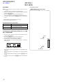
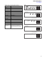
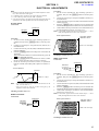
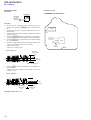
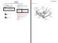
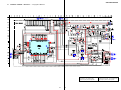
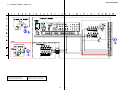
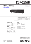
CDP-CE275/CE375
SERVICE MANUAL
US Model
Canadian Model
Australian Model
Ver 1.1 2001.07
CDP-CE275/CE375
AEP Model
UK Model
E Model
CDP-CE375
Photo: CDP-CE375
Model Name Using Similar Mechanism
CDP-CE345
CD Mechanism Type
CDM59-5BD27
Base Unit Name
BU-5BD27
Optical Pick-up Name
PXR-104X
SPECIFICATIONS
Compact disc player
Laser
Frequency response
Dynamic range
Harmonic distortion
General
Semiconductor laser ( λ = 780 nm)
Emission duration : continuous
2 Hz to 20 kHz ± 0.5 dB
More than 93 dB
Less than 0.0045%
Power requirements
Power consumption
Dimensions (approx.)
(w/h/d)
Mass (approx.)
120 V AC, 60 Hz
11 W
430 x 110 x 400 mm
(17 x 4 3/8 x 15 3/4 in.)
incl. projecting parts
5 kg (11 lbs 1 oz)
Outputs
ANALOG
OUT
DIGITAL
OUT
(OPTICAL)
PHONES
(CDP-CE375
only)
Jack
type
Phono
jacks
Optical
output
connector
Stereo
phone
jack
Maximum
output level
2V
(at 50 kilohms)
–18 dBm
10 mW
Load
impedance
Over 10
kilohms
Wave
length:
660 nm
32 ohms
Supplied accessories
Audio cord (2 phono plugs – 2 phono plugs) (1)
Remote commander (remote) (1) (CDP-CE375 only)
R6 (size AA) batteries (2) (CDP-CE375 only)
Design and specifications are subject to change without notice.
COMPACT DISC PLAYER
9-873-822-12
Sony Corporation
2001G0500-1
C 2001.7
Home Audio Company
Shinagawa Tec Service Manual Production Group
CDP-CE275/CE375
Ver 1.1 2001.07
SECTION 4
TEST MODE
ADJ MODE
Connecting Location:
NOTE: This mode cannot be performed without a general remote commander.
– MAIN BOARD (Component Side) –
1. Chuck the CD first, and then turn OFF the power.
2. Short-circuit the test point TP1 (ADJ) of the MAIN board and
ground with a lead wire.
3. Press the [POWER] button to turn ON the power.
The CD is playback automatically and the ADJ mode is set.
4. To exit the mode, press the [POWER] button to turn OFF the
power.
• Prohibits high speed search during accessing
• Ignores even if GFS becomes “L”
ADJ Mode Special Function Table
Button
Function
PLAY MODE
Auto gain display
(Focus, Tracking and Sledding)
EDIT
RFCK → GFS → Error rate display
FLUORESCENT INDICATOR TUBE ALL LIT, AND
KEY CHECK MODE
1. Short-circuit the test TP2 (AFADJ) of the MAIN board and
ground with a lead wire.
2. Press the [POWER] button to turn ON the power.
The whole fluorescent indicator tube lights up.
3. All buttons have individual button numbers.
When a button is pressed, the button number is counted up
and displayed.
1
Count up display
0
TP1 (ADJ)
JW68
Displays button number
When remote controller signals are received, “RM **” will be
displayed.
(** are the numbers corresponding to the remote controller
buttons.)
When using the remote controller, switch the [CD1/2/3] switch
to CD1.
4. To exit the mode, press the [POWER] button to turn OFF the
power.
10
JW66
TP2 (AFADJ)
CN301
CDP-CE275/CE375
Ver 1.1 2001.07
Buttons and Corresponding Button Numbers
Button
DISC1
Button Number or Display
12
DISC2
11
DISC3
10
DISC4
9
DISC5
8
PLAY MODE
20
PEAK SEARCH
19
FADER
18
REPEAT
17
TIME
16
H (PLAY)
Partial lighting 1
X (PAUSE)
Partial lighting 2
x (STOP)
All lit
EX-CHANGE
35
DISC SKIP
36
m
24
M
25
EDIT
26
CHECK
27
CLEAR
28
AMS (push)
AMS (turn)
All lit
ALL1DISCS
REPEAT 1
EDIT
TIME
FADE
A B
PROGRAM
SHUFFLE
DISC
TRACK
PEAK
MIN STEP SEC
1
2 3
4
6
7 8
9 10
5
11 12 13 14 15
16 17 18 19 20
Partial lighting 1
TRACK
MIN
SEC
R Light altemately
r
ALL1DISCS
DISC
PEAK
STEP
1
2 3
6
7 8
4
5
37
When rotated clockwise: The music calendar
numerals light up in ascending order.
When rotated counterclockwise: The music
calendar numerals light up in descending
order.
Partial lighting 2
1
3
7
11
5
9
13
15
18
20
R Light altemately
r
2
6
4
8
10
12
14
16 17
19
11
CDP-CE275/CE375
Ver 1.1 2001.07
AGING MODE
For the aging mode, three modes of all mode, disc table mode, and loading mode are available.
This set has the Aging mode for operation check of the mechanism deck.
• If a failure occurred
The aging operation stops and a faulty status is displayed on the fluorescent indicator tube.
• If no failure occurs
The aging operation continues repeatedly.
Note: Do not use the test disc when performing aging.
Aging will not be performed properly if discs with tracks shorter than 4 seconds are used.
Procedure:
1. Press the [POWER] button and turn ON the power.
2. Set discs on all trays.
(More than two discs if five are not available)
3. All mode:
Press the [CHECK], [PLAY MODE] and x buttons at the same time.
Disc table mode:
Press the [CHECK], [PLAY MODE] and [SKIP] buttons at the same time.
Loading mode:
Press the [CHECK], [PLAY MODE] and [EX-CHANGE] buttons at the same time.
4. Aging starts, and the fluorescent indicator tube will display the following.
5. To exit the mode, press the [POWER] button to turn OFF the power.
Code No.
Status
All mode
Disc table
mode
Loading
mode
Display in
Normal operation
Display in
case of failure
a
A-0
Err 0
a
a
A-1
Err 1
Err 2
0
CLOSE (Tray closed)
a
1
TOC reading
a
2
Access to last track
a
A-2
3
Play of last track (3 sec)
a
Counter display
Err 3
4
EX OPEN (Tray opened while chucking)
a
A-4
Err 4
5
EX SKIP (Disc tray rotated)
a
A-5
Err 5
6
EX CLOSE (Tray closed)
a
7
Access to first track
a
8
Play of first track (3 sec)
a
9
OPEN (tray opened)
a
A
DISC SKIP (Disc tray rotated,
and next disc was selected)
a
a
a
a
a
A-6
Err 6
A-7
Err 7
Counter display
Err 8
A-9
Err 9
A-A
Err A
The discs are selectie in the order of DISC1 →DISC2 → DISC3 → DISC4 → DISC5 → DISC1 → .... Empty trays are skipped.
But the order is random in the disc table mode.
MECHANISM DECK CHECK MODE
For the mechanism deck check mode, two modes of disc table mode and loading mode are available.
In the mechanism deck check mode, the disc table turning time and the loading time in each section are measured and displayed.
Procedure:
Disc table mode:
Press the [POWER] switch while pressing H , [A OPEN/CLOSE] and [REPEAT] buttons simultaneously.
Loading mode:
Press the [POWER] switch while pressing H , [A OPEN/CLOSE] and [TIME] buttons simultaneously.
Display contents
Mode
Disc table mode
(
Table turning
time measurement
)
Check command
Display
0: Right one turn
r 12.5
1: Left one Turn
L 10.2
2: Measurement end
r 12.5
3: Undefined
Table mode
(
12
Loading time
measurement
)
4: Star position
Sta – –.–
5: Open → Close
CLo 10.2
6: Close → BU up
UP
0.7
7: BU up → EX open
EoP
6.2
8: EX open → EX close
ECL 10.3
9: EX close → BU down
don
1.2
A: BU down → Open
oPn
9.3
FF: Measurement end
CLo 10.2
CDP-CE275/CE375
Ver 1.1 2001.07
SECTION 5
ELECTRICAL ADJUSTMENTS
Note:
1. CD Block is basically designed to operate without adjustment. Therefore, check each item in order given.
2. Use PATD-012 disc (4-225-203-01) unless otherwise indicated.
3. Use an oscilloscope with more than 10MΩ impedance.
4. Clean the object lens by an applicator with neutral detergent when the
signal level is low than specified value with the following checks.
S Curve Check
Connection:
oscilloscope
BD board
TP (FE1)
TP (VC)
Procedure:
1. Set the test disc (PATD-012). Disc chucking operation is
complete, then press the [POWER] button to turn the power
off.
2. Connect an oscilloscope to test point TP (RFDC) and TP (VC)
on the BD board.
3. Connect between test point TP (ADJ) on the MAIN board and
GND by lead wire.
4. Press the [POWER] button to turn the power on and enter the
ADJ mode, then playback the number two track automatically.
5. Confirm that oscilloscope waveform is clear and check the level
of between RFDC top and VC is correct or not.
Note: A clear RFDC signal waveform means that the shape “◊” can be
clearly distinguished at the center of the waveform.
+
–
RFDC signal waveform
Procedure:
1. Set the test disc (PATD-012). Disc chucking operation is
complete, then press the [POWER] button to turn the power
off.
2. Connect an oscilloscope to test point TP (FE1) and TP (VC)
on the BD board.
3. Connect between test point TP (ADJ) on the MAIN board and
GND by lead wire.
4. Press the [POWER] button to turn the power on and enter the
ADJ mode.
Then playback the number two track automatically, press the
x button to stop the playback.
5. Press the [CHECK] button actuate the focus search. (actuate
the focus search when disc table is moving in and out)
6. Check the oscilloscope waveform (S-curve) is symmetrical
between A and B. And confirm peak to peak level within 2 ± 1
Vp-p.
level: 1.15 ± 0.35 Vp-p
VC
Checking Location: BD board
RFAC Level Check
Connection:
oscilloscope
BD board
TP (RFAC)
TP (VC)
S-curve waveform
VOLT/DIV: 200 mV
TIME/DIV: 500 ns
+
–
symmetry
A
within 2 ± 1 Vp-p
B
Note: • Try to measure several times to make sure than the ratio of A : B
or B : A is more than 10 : 7.
• Take sweep time as long as possible and light up the
brightness to obtain best waveform.
Checking Location: BD board
Procedure:
1. Set the test disc (PATD-012). Disc chucking operation is
complete, then press the [POWER] button to turn the power
off.
2. Connect an oscilloscope to test point TP (RFAC) and TP (VC)
on the BD board.
3. Connect between test point TP (ADJ) on the MAIN board and
GND by lead wire.
4. Press the [POWER] button to turn the power on and enter the
ADJ mode, then playback the number two track automatically.
5. Confirm that oscilloscope waveform is clear and check RFAC
signal level is correct or not.
Note: A clear RFAC signal waveform means that the shape “◊” can be
clearly distinguished at the center of the waveform.
RFDC Level Check
Connection:
oscilloscope
RFAC signal waveform
BD board
TP (RFDC)
TP (VC)
VOLT/DIV: 200 mV
TIME/DIV: 500 ns
+
–
level: 1.35 ± 0.4 Vp-p
Checking Location: BD board
13
CDP-CE275/CE375
Ver 1.1 2001.07
E-F Balance Check
Connection:
Checking Location:
– BD BOARD (Conductor Side) –
oscilloscope
BD board
TP (TE1)
TP (VC)
+
–
Procedure:
1. Set the test disc (PATD-012). Disc chucking operation is
complete, then press the [POWER] button to turn the power
off.
2. Connect an oscilloscpe to test point TP (TE1) and TP (VC) on
the BD board.
3. Connect between test point TP (ADJ) on the MAIN board and
GND by lead wire.
4. Press the [POWER] button to turn the power on and enter the
ADJ mode, then playback the number two track automatically.
5. Press the [TIME] button. (The tracking servo and the sledding
servo are turned OFF)
6. Check the level B of the oscilliscope waveform and the A (DC
voltage) of the center of the Traverse waveform.
Confirm the following :
A/B x 100 = less than ± 22%
Traverse Waveform
Center of
the waveform
B
A (DC
voltage)
0V
level: 1.15 ± 0.5 Vp-p
Press the [TIME] button. (The tracking servo and sledding servo
are turned ON)
Confirm the C (DC voltage) is almost equal to the A (DC
voltage) is step 6.
7.
Traverse Waveform
C (DC
voltage)
0V
Tracking servo
Sled servo
OFF
Checking Location: BD board
14
Tracking servo
Sled servo
ON
IC150
TP
(VC)
IC131
TP
(FE1)
IC101
TP
(TE1)
TP
(RFDC)
TP
(RFAC)
CDP-CE275/CE375
SECTION 6
DIAGRAMS
6-1.
• Circuit Boards Location
NOTE FOR PRINTED WIRING BOARDS AND SCHEMATIC DIAGRAMS
Note on Printed Wiring Board:
• X : parts extracted from the component side.
• Y : parts extracted from the conductor side.
•
: Pattern from the side which enables seeing.
(The other layers' patterns are not indicated.)
Caution:
Pattern face side:
(Conductor Side)
Parts face side:
(Component Side)
Parts on the pattern face side seen from
the pattern face are indicated.
Parts on the parts face side seen from
the parts face are indicated.
• Indication of transistor
Q
B C
E
These are omitted.
Q
B
C
E
These are omitted.
Note on Schematic Diagram:
• All capacitors are in µF unless otherwise noted. pF: µµF
50 WV or less are not indicated except for electrolytics
and tantalums.
• All resistors are in Ω and 1/4 W or less unless otherwise
specified.
f
: internal component.
•
• C : panel designation.
Note:
The components identified by mark 0 or dotted
line with mark 0 are critical for safety.
Replace only with part
number specified.
SENSOR board
LOADING MOTOR board
BD board
POWER SW board
Note:
Les composants identifiés par
une marque 0 sont critiques
pour la sécurité.
Ne les remplacer que par une
pièce por tant le numéro
spécifié.
• Voltages and waveforms are dc with respect to ground
under no-signal conditions.
no mark : CD PLAY
• Voltages are taken with a VOM (Input impedance 10 MΩ).
Voltage variations may be noted due to normal production tolerances.
• Waveforms are taken with a oscilloscope.
Voltage variations may be noted due to normal production tolerances.
• Circled numbers refer to waveforms.
• Signal path.
J : CD PLAY
c : DIGITAL OUT
• A: B+ Line
• B: B– Line
JUNCTION board
KEY board
MAIN board
DISPLAY board
HEADPHONE board
15
15
CDP-CE275/CE375
Ver 1.1 2001.07
6-3.
SCHEMATIC DIAGRAM – BD Board –
• See page 24 for Waveforms.
• See page 24 for IC Block Diagrams.
TP
(RFAC)
IC BD
TP
(RFDC)
TP
(TE1)
TP
(VC)
TP
(FE1)
TP
(SE1)
IC BD
(Page 21)
The components identified by mark 0 or dotted
line with mark 0 are critical for safety.
Replace only with part number specified.
17
17
Les composants identifiés par une marque 0 sont
critiques pour la sécurité. Ne les remplacer que
par une pièce portant le numéro spécifié.
CDP-CE275/CE375
6-5.
SCHEMATIC DIAGRAM – JUNCTION/SENSOR/LOADING MOTOR Boards –
• See page 25 for IC Block Diagram.
TO MAIN BOARD
(Page 21)
IC BD
19
19
CDP-CE275/CE375
6-7.
SCHEMATIC DIAGRAM – MAIN Board –
• See page 24 for Waveform.
(Page 23)
(Page 17)
(Page 23)
(Page 23)
(Page 19)
The components identified by mark 0 or dotted
line with mark 0 are critical for safety.
Replace only with part number specified.
21
21
Les composants identifiés par une marque 0 sont
critiques pour la sécurité. Ne les remplacer que
par une pièce portant le numéro spécifié.
CDP-CE275/CE375
6-9.
SCHEMATIC DIAGRAM – PANEL Section –
(Page 21)
(Page 21)
(Page 21)
The components identified by mark 0 or dotted
line with mark 0 are critical for safety.
Replace only with part number specified.
Les composants identifiés par une marque 0 sont
critiques pour la sécurité. Ne les remplacer que
par une pièce portant le numéro spécifié.
23
23