1
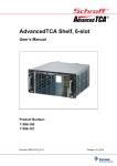
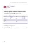
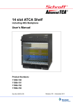
33-1892 CB1-inst8-02.qxd
9/23/02
2:27 PM
Page 1
INSTALLATION INSTRUCTIONS
CB1
ONE ZONE CONNECTING BLOCK
EMITTERS
SIGNAL
GND
PWR
GND
CB1
ONE ZONE
CONNECTING BLOCK
+12VDC
The Model CB1 provides a quick low cost means of
connecting all Sonance IR Receivers and Keypads
to four single or four dual emitters and a power
supply in an infrared repeater system. It can also
provide a low cost means of emitter expansion in
existing systems, or to connect multiple emitters at
the output of other Sonance devices, such as the
ACB1 Amplified Connecting Blocks.
IR
RCVR
Fig. 1 CB1 One Zone Connecting Block
Mounted in 3” SNAPTRACK™
(SNAPTRACK is a registered trademark of AUGAT)
SPECIFICATIONS
• Inputs: 1-Screw type 4-terminal plug-in. 1-IR Receiver “IR RCVR” 3.5 mm stereo mini jack.
• Outputs: 4-Emitter ports (3.5mm mono mini jacks) parallel driven.
• Contains a 470 Ohm resistor in series with each emitter output.
• Sonance E1, VE1, E2 & VE2 Mini Emitters may be used.
• Power requirements: 12 volts DC. Uses PS1 or PS2 Power Supplies. NOTE: A power supply is not
connected to the CB1 when it is used as an emitter expander.
• 2.1 mm coaxial power jack.
• Dimensions: 2-3/8" W x 3" D x 13/16" H.
INSTALLATION
Fig. 2, next page, illustrates a typical installation using the CB1 in an IR repeater system. A variety of
Sonance IR Receivers are shown. When configuring a system, please keep the following items in mind:
1. More IR Receivers may be wired in parallel, in the same manner as shown, up to a maximum of twelve.
More than twelve is not recommended because IR noise picked up by the many IR receivers may cause
erratic operation and reduce remote control range.
2. Be sure to connect the +12V, Output, and GND of each IR Receiver and keypad to the respective
+12VDC, SIGNAL, and GND of the connecting block as shown.
3. Please Note:
a) Each IR receiver draws 10 milliamps.
b) The maximum current for proper operation from the PS1 Power Supply is 200 milliamps.
c) The maximum current for proper operation from the PS2 Power Supply is 1000 milliamps.
d) When using combinations of keypads and receivers, do not exceed the maximum current of the power
supplies as noted above.
For example, 6 receivers and 8 emitters could be used with one PS1 Power Supply. If the current
capability of the PS1 will be exceeded, use the PS2 Power Supply instead.
CAUTION: Do not use unregulated 12V power supply adapters from other manufacturers. These
may deliver excessive voltage to the IR receivers and cause them to “latch-up”. When this occurs,
the “talk-back” LEDs and VE1 Visible emitters (if used) will stay on continuously!
4. For clarity, connections in this illustration are shown going to a 3-conductor bus in a "daisy chain"
fashion. In an actual installation, however, it is recommended that 3-conductor "home-runs" be pulled from
each room to the CB1 Connecting Block in the main room. This maintains higher power supply voltage to
each IR receiver and keypad for best operation.
5. The "IR RCVR" jack on the CB1 allows the SMR1P and the CR1 (with a 3.5 mm stereo mini plug) to be
plugged directly into the CB1. You can do this when the CB1 Connecting Block is within reach of the 7-foot cable;
such as when installing the SMR1P in a cabinet where the controlled equipment is behind closed doors.
CAUTION: Plug only Sonance IR Receivers equipped with a stereo mini plug into the IR RCVR jack.
Do not plug in emitters or other devices; to do so will destroy emitters and damage power supplies!
6. The emitter ports are driven in parallel with a 470 Ohm resistor connected in series with each port. The
resistors ensure proper current sharing to each emitter. When using less than 4 emitters, you may plug
them into any of the 4 emitter ports without regard to order.
Pg 1
33-1892 CB1-inst8-02.qxd
2:27 PM
ROOM 3
ROOM 2
Micro IR Receivers
WMR1
WALL MOUNT
IR RECEIVER
MR1 Series
IR Receivers
+12V
OUT
Red
Stripe
+12V
GND
OUT
ROOM 4
+12V
GND
SMR1 Series
3-Wire
Cable
Page 2
3-Wire
Cable
+12V
WMR1
OUT
CR1
CR1
Connecting
Block
Wall Mount
IR Receiver
On-Cabinet
IR Receiver
7 Foot Quick
Connect Cable
OUTPUT
GND
GND
PS1
Red
Stripe
+12V
IR
RCVR
PWR OUT
ROOM 1
9/23/02
Power
Supply
120 VAC
(Unswitched; see NOTE 1)
Satellite Receiver
OUT
GND
CB1
Connecting Block
GND
SIGNAL
IR
RCVR
See Item 4
Fig. 2 A Typical CB1 System
7 Foot 3-Conductor
Cable with Quick
Connect Stereo Mini Plug
E1 Emitter
AV Receiver
EMITTERS
GND
CB1
ONE ZONE
CONNECTING BLOCK
PWR
+12VDC
E1 Emitter
DVD
SMR1P
Surface Mount IR
Receiver w/Mini Plug
CAUTION:
VE1 IR
Emitter
VE2 Dual
IR Emitter
(to other
controlled
devices)
See text, item 5.
MAIN ROOM, EQUIPMENT CABINET, ETC.
7. Because of this current sharing feature, you may plug in any combination of emitter models E1, VE1, E2, &
VE2 to the CB1 (up to a maximum of 8
individual emitters) to drive the desired number of devices.
NOTE 1: Be sure the PS1 Power Supply is plugged into an un-switched AC outlet. This maintains
the system in "standby" operation so that power-on commands can be sent to the controlled
equipment.
IMPORTANT NOTE: When using long lengths (more than 200 feet) of inter-room shielded cable, it
may be necessary to connect a 470 ohm 1/8 watt resistor between input (signal) and GND at the
IR input terminals of Sonance Connecting Blocks, Zone Controllers, etc. Refer to Fig. 3. The
resistor discharges the cable capacitance more quietly, allowing IR codes of high bit rates to
pass without data loss.
Fig. 3: 470 Ohm Capacitance Discharge Resistor (for shielded cable longer than 200 feet.)
Typical Input Terminals of Connecting
Block, Zone Controller, Etc.
Ground Shield as shown
+12 VDC
GND
GND
CB1 Input
Terminal
SIGNAL
Shielded Cable
to remote room
470 Ohm resistor
Pg 2
SONANCE • 212 Avenida Fabricante • San Clemente, CA 92672
Tech Support (800) 582-0772 www.sonance.com ©2002 All rights reserved.
33-1892 8.02