1
ATCA FlexChassis 12U (14-Slot) DC
User Manual
Document CC08100
9450 Carroll Park Drive
San Diego, CA 92121-2256
858-882-8800
www.ccpu.com
Document CC08100
FlexChassis™ ATCA 12U (14-Slot) DC
User Manual
© 2001-2009 Continuous Computing Corporation. All rights reserved.
The information contained in this document is provided “as is” without any express representations of warranties.
In addition, Continuous Computing Corporation disclaims all implied representations and warranties, including any
warranty of merchantability, fitness for a particular purpose, or non-infringement of third party intellectual property
rights.
This document contains proprietary information of Continuous Computing Corporation or under license from third
parties. No part of this document may be reproduced in any form or by any means or transferred to any third party
without the prior written consent of Continuous Computing Corporation.
Continuous Computing, the Continuous Computing logo, Create | Deploy | Converge, Embedded Solution
Partners, The Embedded Solution Experts, Flex8, Flex21, FlexChassis, FlexCompute, FlexCore, FlexDSP,
FlexPacket, FlexStore, FlexSwitch, FlexTCA, Quick!Start, TAPA, Trillium, Trillium+plus, the Trillium logo, and
upSuite are trademarks or registered trademarks of Continuous Computing Corporation. Other names and brands
may be claimed as the property of others.
The information contained in this document is not designed or intended for use in human life support systems,
on-line control of aircraft, aircraft navigation or aircraft communications; or in the design, construction, operation or
maintenance of any nuclear facility. Continuous Computing Corporation disclaims any express or implied warranty
of fitness for such uses.
Document CC08100
FlexChassis™ ATCA 12U (14-Slot) DC
User Manual
Table of Contents
Table of Contents ......................................................................................................................................3
Figures ........................................................................................................................................................5
Tables..........................................................................................................................................................6
1. Safety......................................................................................................................................................7
1.1. Safety Symbols used in this document ..................................................................................7
1.2. General Safety Precautions.....................................................................................................7
1.3. References Documentation .....................................................................................................7
1.4. Product Definition ......................................................................................................................8
1.5. Part Number ...............................................................................................................................8
1.6. Terms and Acronyms................................................................................................................8
1.7. Shelf Specification.....................................................................................................................9
1.8. Shelf Dimensions.....................................................................................................................10
1.9. Subrack .....................................................................................................................................10
1.10. Top Front Cover Panel .........................................................................................................10
1.11. Cable Management...............................................................................................................10
1.12. Air Intake Panel .....................................................................................................................10
1.13. Air Filter...................................................................................................................................10
1.14. Rear Hex Panel .....................................................................................................................10
1.15. Rear Lower Section ..............................................................................................................10
1.16. ESD Wrist Strap Terminals..................................................................................................11
2. Board Specifications...........................................................................................................................12
2.1. Midplane....................................................................................................................................12
2.1.1. SEEPROMs ......................................................................................................................12
2.1.2. Shelf SEEPROM Locations............................................................................................13
2.1.3. Logic Ground ....................................................................................................................14
2.2. FTM Distribution Board...........................................................................................................14
2.3. Interconnect Board ..................................................................................................................14
3. Shelf Manager .....................................................................................................................................15
4. Shelf Alarm Panel ...............................................................................................................................16
4.1. Introduction...............................................................................................................................16
4.2. DSAP.........................................................................................................................................16
4.3. DSAP Block Diagram..............................................................................................................17
4.4. DSAP SEEPROM....................................................................................................................17
4.5. DSAP I²C Addresses ..............................................................................................................17
4.6. Connection between Shelf Manager and DSAP ................................................................18
4.7. SAP Telco Alarms ...................................................................................................................18
4.7.1. Telco Alarm Interface ......................................................................................................18
4.7.2. Telco Alarm LEDs ............................................................................................................18
4.7.3. Alarm Silence Push Button.............................................................................................18
4.7.4. Alarm Reset ......................................................................................................................19
4.8. SAP Connectors ......................................................................................................................19
4.8.1. SAP Telco Alarm Connector (DB15-male) Figure 16: Telco Alarm Connector .....19
4.8.2. Shelf Alarm Panel Backplane Connector .....................................................................20
4.9. SAP Temperature Sensor ......................................................................................................21
4.10. SAP PCA9555 .......................................................................................................................21
4.11. RS-232 Serial Console Interface on Shelf Alarm Panel .................................................21
4.12. SAP Console Cable for the Shelf Manger Serial Interface.............................................23
Document CC08100
FlexChassis™ ATCA 12U (14-Slot) DC
User Manual
5. Fan Trays Modules.............................................................................................................................24
5.1. Introduction...............................................................................................................................24
5.2. Functional Description ............................................................................................................24
5.3. Construction .............................................................................................................................24
5.4. Fan Tray Block Diagram.........................................................................................................24
5.5. Fan Tray Signals .....................................................................................................................26
5.6. Fan Tray Temperature Sensor ..............................................................................................26
5.7. Fan Tray Connectors and Indicators....................................................................................26
5.8. Fan Tray IPMB Addresses.....................................................................................................27
5.9. Redundancy .............................................................................................................................27
6. Power Entry Module (PEM)...............................................................................................................28
6.1. Introduction...............................................................................................................................28
6.2. Construction .............................................................................................................................28
6.3. Dimensions...............................................................................................................................28
6.4. Cabling ......................................................................................................................................28
6.5. Compliance...............................................................................................................................28
6.5.1. Surge Compliance............................................................................................................28
6.5.2. EFT Compliance...............................................................................................................29
6.6. PEM Components ...................................................................................................................29
6.7. PEM Block Diagram................................................................................................................30
6.8. PEM IPMB addresses.............................................................................................................30
6.9. Power Distribution ...................................................................................................................30
6.10. Specification for the power connection cables .................................................................31
6.11. PEM Signals...........................................................................................................................31
6.12. PEM Connectors and Indicators .........................................................................................32
6.13. PEM Connector Pin Assignment ........................................................................................32
7. Thermals ..............................................................................................................................................34
7.1. Typical Airflow Velocities through the slots .........................................................................35
7.2. Thermal Power Dissipation at Various ∆T...........................................................................36
7.3. Fan Failure Mode ....................................................................................................................36
8. Service Interval....................................................................................................................................37
8.1. Calculations ..............................................................................................................................37
8.1.1. 25C Ambient Temperature .............................................................................................38
8.1.2. 35C Ambient Temperature .............................................................................................39
8.1.3. 40C Ambient Temperature .............................................................................................40
8.2. Summary...................................................................................................................................40
9. Technical Data ....................................................................................................................................41
Document CC08100
FlexChassis™ ATCA 12U (14-Slot) DC
User Manual
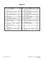
Figures
I.D.
1
Figure
Page
Power Segmentation
12
I.D.
11
Figure
Page
RS-232 Serial Console Interface on
22
Shelf Alarm Display
2
Shelf SEEPROM Locations (1)
13
12
RJ45 to DB9 Serial Console Cable
23
Cisco option (default)
3
Shelf SEEPROM Locations (2)
14
13
RJ45 to DB9 Serial Console Cable
23
EIA/TIA option
4
Logic Ground
14
14
Fan Tray Block Diagram
25
5
Shelf Manager Components
15
15
PEM Components
29
6
Front Panel DSAP
16
16
PEM Block Diagram
30
7
DSAP Block Diagram
17
17
General airflow path for the 12U
34
14-slot ATCA Shelf
8
Connection
between
Shelf
18
18
Front slot Air Velocities
35
Connector
19
19
Rear slot Air Velocities
35
Shelf Alarm Panel Backplane
20
20
Thermal
Manager and DSAP
9
Telco
Alarm
(DB15-male)
10
Connector
Document CC08100
Power
Dissipation
at
36
Various ∆T
FlexChassis™ ATCA 12U (14-Slot) DC
User Manual
Tables
I.D.
Table
Page
1
Terms and Acronyms
8
2
14-Slot ATCA backplane physical to logical slot mapping
12
3
DSAP I²C Addresses
17
4
Telco Alarm LEDs
18
5
Telco Alarm Connector (CN2) Pin Assignment
19
6
Shelf Alarm Panel Backplane Connector Pin Assignment
20
7
PCA9555 Device Function
21
8
RS-232 Serial Connector Cisco Pin assignment (default)
22
9
RS-232 Serial Connector EIA/TIA Pin assignment
22
10
Fan Tray Backplane Connector pin assignment
25
11
Fan Tray Sensors
26
12
LEDs on Fan Tray front panel
27
13
Fan Tray IPMB Addresses
27
14
PEM IPMB addresses
30
15
PEM Sensors
31
16
LEDs on Fan Tray front panel
32
17
PEM Connector pin assignment
32
18
Technical Data
41
Document CC08100
FlexChassis™ ATCA 12U (14-Slot) DC
User Manual
1. Safety
The intended audience of this User’s Manual is system integrators and
hardware/software engineers.
1.1. Safety Symbols used in this document
Caution!
This is the user caution symbol. It indicates a condition where damage of the
equipment or injury of the service personnel could occur. To reduce the risk
of damage or injury, follow all steps or procedures as instructed.
1.2. General Safety Precautions
Warning!
Voltages over 60 VDC can be present in this equipment. As defined in the
PICMG 3.0 Specification, this equipment is intended to be accessed, to be
installed and maintained by qualified and trained service personnel only.
o
Service personnel must know the necessary electrical safety, wiring and connection practices
for installing this equipment in a telecommunication environment.
o
Install this equipment only in compliance with local and national electrical codes.
o
For additional information about this equipment, see the PICMG 3.0 Specification
(www.picmg.com).
1.3. References Documentation
These documents contain information and specifications related to the requirements listed in this document.
o Requirements as outlined in PICMG 3.0, AdvancedTCA Base Specification
o
o
o
Requirements as outlined in PICMG® 3.0 R2.0 ECN-001 AdvancedTCA Specification
Requirements as outlined in PICMG® 3.0 R2.0 ECN-002 AdvancedTCA Specification
Pigeon Point Systems IPM Sentry User Guide and External Interface
Document CC08100
FlexChassis™ ATCA 12U (14-Slot) DC
User Manual
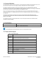
1.4. Product Definition
The AdvancedTCA (ATCA) 14-Slot FlexChassis is a fault tolerant/high availability shelf designed for use in a 19”
rack mount and occupies 12U of rack height, including a dedicated area for cable management.
The airflow is optimized for efficient cooling from the angled air entry to the patented Serial Parallel Fan
Arrangement. This Shelf works with the 200W/board power dissipation capabilities of ATCA plug-in modules with
low noise due to the speed controlled, IPMI based, hot pluggable fan trays.
Each of the redundant power entry modules (PEMs) protect and filter the potential 2800W that the plug-in
modules may dissipate. The PEMs plug directly into the ATCA midplane and deliver power to the backplane in
four segments.
The Pigeon Point IPM Sentry is the heart of the ATCA 14-Slot FlexChassis Shelf Management. Each
ATCA slot as well as the fan trays, PEMs, and Shelf Alarm Panel communicate with the Shelf Management
Modules via the IPMBs.
The midplane provides the communications path, not only for the plug-in boards, but the PEM, and shelf
management modules (ShMM).
1.5. Part Number
Part Number
Module
5-02389
FlexChassis ATCA 12U, 19", 14-slot, Dual Star, 2 PEMs, 3 Fan Tray
Modules, 1 IPMI monitored air filter
The Shelf Managers and the Shelf Alarm Panel are not included with the Shelf
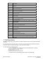
1.6. Terms and Acronyms
Table 1: Terms and Acronyms
Term
ATCA or
AdvancedTCA
Backplane
Definition
Advanced Telecom Computing Architecture
Passive circuit board providing the connectors for the front boards. Power distribution,
management and auxiliary signal connections are supported
CFM
Cubic Feet per Minute
Chassis
Physical structure containing boards, backplane, PEMs, etc.; same as Shelf
CPU
Computer Processing Unit
DC
Direct Current
EMI
Electromagnetic Interface
ESD
Electrostatic Discharge
ETSI
Fabric Board
Fabric Slot
European Telecommunications Standards Institute
A board intended for use in a star topology backplane that provides connectivity to a
number of Node Boards within the backplane.
A slot in a backplane that is capable of supporting Fabric Boards, Mesh Enabled
Boards or Node Boards.
FRU
Field Replaceable Unit
FTM
Fan Tray Module
Document CC08100
FlexChassis™ ATCA 12U (14-Slot) DC
User Manual
HA
High Availability
I2C
Inter-integrated Circuit bus
I/O
Input/Output
IEEE
Institute of Electrical and Electronic Engineers
IPM
Intelligent Platform Management
IPMI
Intelligent Platform Management Interface
IPMB
Intelligent Platform Management Bus
IPMB-0
This is the logical aggregation of the two IPMB busses called IPMB-A and IPMB-B.
JTAG
Joint Test Action Group
Kbps
Kilo Bits Per Second
LED
Light Emitting Diode
LFM
Linear Feet per Minute
NEBS
Network Equipment Building Standards
Node Board
Node Slot
A board intended for use in a star topology backplane that has connectivity to a Fabric
Board within the backplane.
A slot supporting port connections to/from Fabric Slot(s). A Node slot is intended to
accept a Node Board.
PCB
Printed Circuit Board
PEM
Power Entry Module
PICMG
PCI Industrial Computer Manufacturers Group
RTC
Real Time Clock
RTM
Rear Transition Module
SAP
Shelf Alarm Panel
SEL
System Event Log
Shelf
See Chassis
ShMC
Shelf Manager Carrier Board
Star
A backplane topology in which there is one or more dedicated channel connections
between each node Slot and the Fabric Slots.
U
Unit of vertical pitch. 1 U = 1.75 inches = 44.45 mm
Zone 2
ATCA terminology for the data interconnect portion (top) of the backplane.
Zone 3
ATCA terminology for the open region above the backplane where front board and
RTMs connect.
1.7. Shelf Specification
The Shelf is 12U high and 19” rack mountable. The chassis is designed for easy access of any field replaceable
units (FRU).
The chassis and subrack comply with ATCA 3.0 section 2.0 mechanical requirements and the subrack support
fourteen 8U x 280mm front plug boards and 8U x 70mm rear transition modules.
The Shelf implements the following features:
o
14 slot ATCA Backplane, dual-star Base Interface and bused IPMB interface, supporting
twelve node board slots and two hub slots
o
Mounting brackets for 19” racks
o
ESD Wrist Strap Terminals at front and rear
o
Two dedicated slots for a Shelf Manager based on Pigeon Point ShMM-500R
Document CC08100
FlexChassis™ ATCA 12U (14-Slot) DC
User Manual
o
One dedicated slot for a Shelf Alarm Panel (SAP) that provides Telco Alarm interface, Alarm
Status LEDs and serial interface for the Shelf Manager
o
Three front pluggable fan trays with 4 high speed fans per tray
o
Removable air filter that meets the requirements of the Telcordia GR-78-CORE specification
o
Two rear pluggable Power Entry Modules
1.8. Shelf Dimensions
The Shelf height is 12U with a 14slot x 8U x 280mm card cage. The configuration allows for the Hub slots to be in
physical slots 7 and 8. The rear transition area is 14slot x 8U x 70mm. The Shelf is front rack mountable and has
provisions for mid mounting. The Shelf has been designed for easy access of field replaceable units (FRU).
1.9. Subrack
The Subrack complies per PICMG 3.0 section 2.0 for subracks to support fourteen 8U x 280mm front plug
modules and fourteen 8U x 70mm rear transition modules. A slot zero is needed for the two Shelf Managers and
one Shelf Alarm Panel.
The front and the rear of the Shelf provide for an ESD wrist strap terminal.
1.10. Top Front Cover Panel
The Shelf provides for a cosmetic front panel installed in front of the upper FTMs. This provides space for a logo
and contains the labeling for the ATCA blade slots with their physical slot number, Hub slots 7 and 8 are labeled
red.
1.11. Cable Management
The Shelf provides for a low profile cable management system.
1.12. Air Intake Panel
A lower front removable air intake panel provides the EMI containment for the lower section of the Shelf. The
panel is easily removable via two fasteners.
1.13. Air Filter
The air filter is easily removable from beneath the card cage. This filter element is an open-cell polyurethane foam
specially coated to provide improved fire retardation and fungi resistance. It features deep loading, large dust
holding capacity, low air resistance, and complies with NEBSGR-63-CORE.
There is a switch to detect whether an air filter is installed. This switch is exposed to the Shelf manager as a
presence sensor on the Power Entry Modules.
1.14. Rear Hex Panel
A removable rear hex panel allows for a low-impedance exhaust, attenuates EMI while providing protection from
the rotating fans and helps prevent flames from exiting the Shelf in case of a fire.
1.15. Rear Lower Section
The lower rear section contains provisions for the Power Entry Modules. The structure allows for the FRUs to be
easily removed and secured while also providing additional structural integrity to the Shelf.
Document CC08100
FlexChassis™ ATCA 12U (14-Slot) DC
User Manual
1.16. ESD Wrist Strap Terminals
One ESD Wrist Strap Terminal is located at the upper front side and one ESD Wrist Strap Terminal is located at
the upper rear side of the chassis.
Document CC08100
FlexChassis™ ATCA 12U (14-Slot) DC
User Manual
2. Board Specifications
Within the Shelf, there are three fixed boards:
o
Midplane
o
FTM Distribution board
o
Interconnect board
These boards are completely passive and are not Field Replaceable Units. The Interconnect board provides
power and signals from the Backplane to the FTM Distribution board and eliminates the use of cables within the
chassis. This improves the reliability of the Shelf.
2.1. Midplane
The standard backplane is based upon PICMG 3.0 specifications for mechanical attachment to the card cage. The
backplane is mounted in such a way as to allow for replacement with minimal chassis disassembly (requires
removal of PEM, Payload boards, ShMC’s, and Interconnect board), using only simple tools such as screw and
nut drivers. The backplane is not a FRU. Hub slots (2) are located in physical slot 7 and slot 8. The backplane
PCB is made from IS610 material and provides dual-star Base Interface and dual-star Fabric Interface
connections at each node slot with Segmented power (Section 2.1.1), and direct mating to the PEM. Backplane
tests show performance at 3.12Gb/s with margin up to 4Gb/s. The channel skews are less than 6ps. The Shelf
Manager cards and Shelf Alarm Panel are designed to be installed via the right section of the backplane (slot 0).
The PEMs are installed in the rear section of the backplane along with the Interconnect board.
Table 2: 14-Slot ATCA backplane physical to logical slot mapping
Figure 1: Power Segmentation
2.1.1. SEEPROMs
The SEEPROMs are the repository of the shelf specific information capabilities of the system and other
Document CC08100
FlexChassis™ ATCA 12U (14-Slot) DC
User Manual
user configurable options. The SEEPROMs contain the list of which slots are connected together, how the
update channels are routed, how many slots are in the system, what the maximum power is to each slot,
serial number of the shelf, backplane topology, etc. The Shelf Manager uses this information to provide
functions such as electronic keying, controlling the power state of the system, etc.
The SEEPROMs receive redundant 3.3V power from each of the PEMs, which is diode-OR’d. As long as
one PEM has power, the SEEPROMs are functional.
There are two locations in the Shelf where the chassis FRU data can be stored. The default configuration
has the redundant SEEPROMs installed in sockets on the backplane. The Shelf also supports a second
configuration where the chassis FRU data is stored in a SEEPROM located on each PEM.
The Shelf allows for 3 methods to chassis FRU data:
o An I2C connection from each Shelf Manager directly to the SEEPROMs on the backplane.
o SEEPROMs on the backplane exposed as a FRU of the PEMs.
o No SEEPROM on the backplane, but SEEPROM installed in each PEM, exposed as a FRU of the
PEMs.
It is also possible to have SEEPROMs on the backplane and in the PEMs. In this configuration there are
four redundant copies of the chassis FRU data.
The Shelf Managers cache the information that is stored in the SEEPROMs so that the SEEPROM is only
needed when the Shelf Managers are first inserted or when the Shelf is first turned on. The redundant
SEEPROMs ensure that if one is corrupt or non-functional, the second can provide the necessary
information. The Shelf Manager determines which information is correct and then synchronizes the
SEEPROMs from the internally cached copy of the SEEPROM information.
The Shelf Manager periodically accesses both SEEPROMs to ensure that they are responding properly. If
a SEEPROM has failed, the Shelf Manager logs the error and raises an error condition to the upper-level
software. When a blank replacement SEEPROM is inserted into the shelf, the Shelf Manager
automatically detects the newly inserted SEEPROM and synchronizes it with the SEEPROM information
internally cached on the Shelf Manager.
2.1.2. Shelf SEEPROM Locations
There are two locations in the Shelf for SEEPROMs. In the default configuration two redundant
SEEPROMs are located on the Chassis Data Module (CDM). The CDM is a PCB at the upper rear side of
the Shelf. The SEEPROMs are accessible through a removable panel. The I2C address for these
SEEPROMs is 0xA4.
Figure 2: Shelf SEEPROM Locations (1)
The Shelf also provides a second configuration with a SEEPROM located on each PEM.
For the third configuration the I2C connections to the SEEPROMs are configurable by switches (SW1)
and (SW2) on the Backplane.
Document CC08100
FlexChassis™ ATCA 12U (14-Slot) DC
User Manual
Figure 3: Shelf SEEPROM Locations (2)
Default configuration is SW2 closed and SW1 open. The Shelf Mangers have access to the SEEPROMs
via I²C-bus Channel 1 and Channel 2. In an alternate configuration SW2 is open and SW1 is closed so
that the SEEPROMs on the CDM are connected to the internal I2C-bus on the PEMs.
2.1.3. Logic Ground
The ATCA Backplane provides a mechanism to connect Logic Ground and Shelf Ground. To connect
Logic Ground and Shelf Ground mount an additional backplane mounting screw (M3 x 12 mm) with an
adequate washer at a position labeled with “GND“.
Figure 4: Logic Ground
2.2. FTM Distribution Board
The FTM distribution board provides the signal and power connections to the upper FTMs from the backplane.
2.3. Interconnect Board
The interconnect board connects the backplane to the FTM distribution board.
Document CC08100
FlexChassis™ ATCA 12U (14-Slot) DC
User Manual
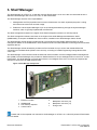
3. Shelf Manager
The Shelf Manager for ATCA 6- & 14-Slot DC-powered FlexChassis is a 78 mm x 280 mm board that fits into a
dedicated Shelf Manager slot in an ATCA 12U, 14-Slot FlexChassis.
The Shelf Manager has two main responsibilities:
1. Manage/track the FRU population and common infrastructure of a Shelf, especially the power, cooling
and interconnect resources and their usage.
2. Enable the overall System Manager to join in the management/tracking through the System Manager
Interface, which is typically implemented over Ethernet.
The Shelf management based on the Pigeon Point Shelf management solution for ATCA products.
The Shelf management software executes on the Pigeon Point Shelf Management Mezzanine 500R
(ShMM-500R), a compact SO-DIMM form-factor module, installed on the Shelf Manager Carrier board.
The Shelf Manager Carrier board includes several on-board devices that enable different aspects of Shelf
management based on the ShMM-500R. These facilities include I²C-based hardware monitoring/control and GPIO
expander devices.
The Shelf Manager Carrier board also provides the Fan Controller for up to 9 fans and individual Ethernet
connections to both Base Hubs (ShMC cross connect), according to PICMG Engineering Change Notice ECN
3.0-2.0-001
The Shelf Manager communicates inside the Shelf with IPM controllers over the Intelligent Platform Management
Bus (IPMB). The Shelf Manager also provides an IPMB interface for the non-intelligent FRUs in the ATCA 14-Slot
FlexChassis. The Shelf Manager communicates with the non-intelligent FRUs over I²C busses and exposes the
sensors for these FRUs at IPMB address 0x20.
Figure 5: Shelf Manager Components
1
Extraction handle
5
2
3
4
ShMM 500R
RTC backup capacitor
Carrier board
6
7
Backplane connector (J2)
Backplane connector (J1)
Fixing screw
Please refer to the separate user manual for Shelf Manager for ATCA 6- & 14-Slot DC-powered FlexChassis
for more details.
Document CC08100
FlexChassis™ ATCA 12U (14-Slot) DC
User Manual
4. Shelf Alarm Panel
4.1. Introduction
Some Shelf Manager I/O functionalities have been moved to a separate board called Shelf Alarm Panel (SAP).
The Shelf provides provisions for one SAP location. The SAP major features are:
o
3 Shelf Alarm LEDs (MINOR, MAJOR, CRITICAL)
o
The Telco Alarm connector (DB15-male)
o
The Alarm Silence
o
A serial console interface for Shelf Managers (RJ45 connector)
The I²C enabled DSAP can only be used together with Shelf Managers
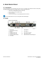
4.2. DSAP
Figure 6: Front Panel DSAP
12706932
1
7
LED USER 2
8
LED USER 3
3
Fixing screw
Serial Interface for Shelf
Manager 1
LED Minor Alarm (red)
9
Telco Alarm Connector
4
LED Major Alarm (red)
10
Alarm Silence button
5
6
LED Critical Alarm (amber)
LED USER 1
11
Serial Interface for Shelf Manager 2
2
Document CC08100
FlexChassis™ ATCA 12U (14-Slot) DC
User Manual
4.3. DSAP Block Diagram
Figure 7: DSAP Block Diagram
12706921
4.4. DSAP SEEPROM
The SAP SEEPROM is connected to the Master-Only I²C-bus and is a Microchip 24LC256 device.
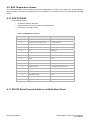
4.5. DSAP I²C Addresses
Table 3: DSAP I²C Addresses
Document CC08100
FlexChassis™ ATCA 12U (14-Slot) DC
User Manual
4.6. Connection between Shelf Manager and DSAP
Figure 8: Connection between Shelf Manager and DSAP
12706933
4.7. SAP Telco Alarms
4.7.1. Telco Alarm Interface
The SAP provides a Telco Alarm interface on the DB15-male connector. Three relay outputs are used for
remote alarm distribution, reflecting the state of the three Alarm LEDs. The relays are capable of carrying
72 VDC or 1 A with a max. rating of 30 VA.
4.7.2. Telco Alarm LEDs
The Shelf Alarm Panel provides the Telco Alarm LEDs. These LEDs indicate presence of Critical, Major
and Minor alarms as follows:
Table4: Telco Alarm LEDs
State
Description
Off
No alarm active
On
Alarm active
Flashing
Alarm active, but silenced
4.7.3. Alarm Silence Push Button
The Alarm Silence push button on the Shelf Alarm Panel faceplate deactivates the alarm relays. During
the time Alarm Silence is activated, the Alarm LEDs flash. By pressing the Alarm Silence push button a
second time, the alarm relays are reactivated and the Alarm LEDs are solid.
The Alarm Silence push button only activates the Alarm Silence state, but does not reset the
Document CC08100
FlexChassis™ ATCA 12U (14-Slot) DC
User Manual
alarms. If the silence interval (default 600 s) is exceeded without resolving the alarms, the alarms will
be re-initiated.
4.7.4. Alarm Reset
Hardware Reset:
Two relay inputs at the DB15 connector are used to reset the Minor and Major alarm state.
The reset inputs accept timed pulse inputs for clearing Minor and Major alarm states. Reset is
accomplished by asserting a voltage differential from 3.3 VDC to 72 VDC for between 200 ms and 300 ms.
The acceptance voltage range is from 0 to 48 VDC continuous (handles up to 60 VDC at a 50% duty
cycle). The current drawn by a reset input does not exceed 12 mA.
There is no hardware reset (reset input) for the Critical Alarm state.
Software Reset:
The RMCP and CLI functions can be used to set and reset the Telco Alarms (incl. Critical Alarm). See the
Pigeon Point Shelf Manager External Interface Reference for more information.
4.8. SAP Connectors
4.8.1. SAP Telco Alarm Connector (DB15-male) Figure 16: Telco Alarm Connector
Figure 9: Telco Alarm Connector (DB15-male)
12705896
Table 5: Telco Alarm Connector (CN2) Pin Assignment
Document CC08100
CN2 Pin
Name
Description
1
AMIR+
Minor Reset+
2
AMIR-
Minor Reset
3
AMAR+
Major Reset+
4
AMAR-
Major Reset
5
ACNO
Critical Alarm - NO
6
ACNC
Critical Alarm - NC
7
ACCOM
Critical Alarm - COM
8
AMINO
Minor Alarm – NO
Minor Alarm – NC
9
AMINC
10
AMINCOM
Minor Alarm – COM
11
AMANO
Major Alarm – NO
12
AMANC
Major Alarm – NC
13
AMACOM
Major Alarm – COM
14
APRCO
Pwr Alarm – NO
15
APRCOM
Pwr Alarm - COM
Shield
Shelf-GND
Shelf Ground
FlexChassis™ ATCA 12U (14-Slot) DC
User Manual
4.8.2. Shelf Alarm Panel Backplane Connector
Figure 10: Shelf Alarm Panel Backplane Connector
12706926
Table 6: Shelf Alarm Panel Backplane Connector Pin Assignment
SAP ATCA Backplane Connector
Pin
1
A
Description
B
Description
-48V_A
-48 V Feed A
-48V_B
-48 V Feed B
C
2
VRTN_A
3
VRTN_B
Description
Voltage return
Feed A
Voltage return
Feed B
4
5
I2C_PWR_A
(1)
I2C_PWR_B
(1)
3.6 V from Shelf
Manager 1
6
GND
Ground
GND
Ground
I2C_PWR_A
(2)
7
SDA_CH0
GND
Ground
I2C_PWR_B
(2)
8
SCL_CH0
Data I²C-bus
Channel 0 (only
DSAP)
Clock I²C-bus
Channel 0 (only
DSAP)
9
INV_ACTIVE_B
Active signal from
Shelf Manager 2
RXD0_ACB1
Receive Data
Shelf Manager 1
RXD0_ACB2
10
DSR_ACB1
DTR_ACB1
DSR_ACB2
11
CD_ACB2
Data Terminal
Ready Shelf
Manager 1
Data Terminal
Ready Shelf
Manager 2
12
CTS_ACB1
13
TXD0_ACB2
14
SDA_A
15
SAP_PRES
16
INV_ACTIVE_A
3.6 V from Shelf
Manager 1
3.6 V from Shelf
Manager 2
3.6 V from Shelf
Manager 2
GND
INT
Receive Data
Shelf Manager 2
(right)
Document CC08100
Data Set Read
Shelf Manager 1
Carrier Detect Shelf
Manager 2
Clear To Send
Shelf Manager 1
Transmit Data Shelf
Manager 2
Data IPMB_A (only
ISAP)
SAP Presence
signal to Shelf
Manager
Active signal from
Shelf Manager
1(left)
DTR_ACB2
CTS_ACB2
TXD0_ACB1
RTS_ACB2
SCL_A
CD_ACB1
RTS_ACB1
Clear To Send
Shelf Manager 2
Transmit Data Shelf
Manager 1
SDA_B
SCL_B
Request To Send
Shelf Manager 2
Data Set Ready
Shelf Manager 2
Carrier Detect
Shelf Manager 1
Request To Send
Shelf Manager 1
Data IPMB_B
(only ISAP
Clock IPMB_B
(only ISAP
Clock IPMB_A (only
ISAP)
SHELF_GND
Shelf Ground
FlexChassis™ ATCA 12U (14-Slot) DC
User Manual
4.9. SAP Temperature Sensor
The LM75 temperature sensor measuring the board temperature is located on the SAP PCB. The temperature
sensor is either connected to the Master-Only I²C-bus (DSAP) or the internal I²C-bus and is accessible via IPMB
(ISAP).
4.10. SAP PCA9555
The PCA9555 device:
o
controls the status of the LEDs
o
reads the status of the Telco Alarm Cutoff push button
o
controls the Telco Alarm relays
Table 7: PCA9555 Device Function
PCA9555 I/O pins
Function
State
0.0
Power Alarm to telco relays output
1 = relays powered
0.1
Minor Alarm to telco relays output
1 = relays powered
0.2
Major Alarm to telco relays output
1 = relays powered
0.3
Critical Alarm to telco relays output
1 = relays powered
0.4
N/C
Pulled High
0.5
LED_MIN (Minor alarm LED) output
1 = On
0.6
LED_MAJ (Major alarm LED) output
1 = On
0.7
LED_CRIT (Critical alarm LED)
output
1 = On
1.0
Alarm Silence button input
0 = push button pushed
1.1
Minor Clear input
0 = voltage applied to input pins
1.2
Major Clear input
0 = voltage applied to input pins
1.3
N/C
Pulled High
1.4
N/C
Pulled High
1.5
LED_USER3 output
1 = On
1.6
LED_USER2 output
1 = On
1.7
LED_USER1 output
1 = On
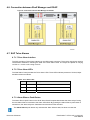
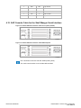
4.11. RS-232 Serial Console Interface on Shelf Alarm Panel
Document CC08100
FlexChassis™ ATCA 12U (14-Slot) DC
User Manual
Figure 11: RS-232 Serial Console Interface on Shelf Alarm Display
1
8
12705811
The Shelf Alarm Panel provides a RS-232 serial console connector for the Shelf Manager 1 and Shelf Manager 2.
The connector is a 8-pin RJ45 modular receptacle.
The DSAP provides two RJ45 connectors.
The ISAP provide just one connector for both Shelf Managers, only the active Shelf Manager
has access to the connector!
A full set of RS-232 signals, including modem control is provided. The serial interface is
implemented on the ShMM-500.
The RS-232 Serial Console Interface is available with EIA/TIA or Cisco pin assignment.
The default configuration is Cisco pinout with:
115200 baud
no parity
8 data bits
1 stop bit
Table 8: RS-232 Serial Connector Cisco Pin assignment (default)
RJ45 Pin
RS-232
Signal
Type
1
RTS
Out
Request To Send
2
DTR
Out
Data Terminal Ready
3
TxD
Out
Transmit Data
4
GND
REF
Logic Ground
5
GND
REF
Logic Ground
6
RxD
In
Receive Data
7
DSR
In
Data Set Ready
8
CTS
In
Clear To Send
Description
Table 9: RS-232 Serial Connector EIA/TIA Pin assignment
Document CC08100
RJ45 Pin
RS-232
Signal
Type
1
DSR
In
Data Set Ready
2
CD
In
Carrier Detect
3
DTR
Out
Description
Data Terminal Ready
FlexChassis™ ATCA 12U (14-Slot) DC
User Manual
4
GND
REF
Logic Ground
5
RxD
In
Receive Data
6
TxD
Out
Transmit Data
7
CTS
In
Clear To Send
8
RTS
Out
Request To Send
4.12. SAP Console Cable for the Shelf Manger Serial Interface
Figure 12: RJ45 to DB9 Serial Console Cable Cisco option (default)
12706929
Figure 13: RJ45 to DB9 Serial Console Cable EIA/TIA option
12706930
The connectors are shown with the cables pointing away.
The serial console cable is not included with the Shelf.
Document CC08100
FlexChassis™ ATCA 12U (14-Slot) DC
User Manual
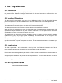
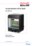
5. Fan Trays Modules
5.1. Introduction
The Shelf has upper Fan Tray Modules (FTM). Each FTM has four 92mm fans and the arrangement is based on
the patented Pentair Electronic Packaging Serial-Parallel Fan Scheme for maximum volume air flow, even
distribution, and fault resilience.
5.2. Functional Description
The fans in the FTM are controlled as a group, via an IPMB-based interface. The IPM Sentry Shelf Manager
performs management of the FTM. The BMR-AVR is used as the IPM Controller in the FTM implementation.
The FTM has an Injector/Ejector handle that interfaces with a micro switch and signals the BMR-AVR for hot-swap.
The handle has a tool accessible fastener that locks the FTM securely into the Shelf.
The Shelf Managers monitor the FTM through the two independent bussed IPMB connections.
When the FTM is first inserted into the system, the fans initially start at full speed and then decrease to 25% of full
speed. The circuitry on-board the fan tray uses pulse-width modulation to set the speed of all the fans. Lower
speeds reduce acoustics and increase the longevity of the fans.
The speed of each fan is monitored. If the fan speed drops below or increases above the desired fan speed, a
system event log (SEL) entry is logged by the Shelf Manager. The Shelf Manager can be configured to then
generate alerts and set alarm conditions as necessary.
The FTM does not negotiate for power with the Shelf Manager and it does not start out at Power Level 0 as
specified in the PICMG 3.0 power management mechanism. This ensures that the fans start up immediately upon
insertion.
5.3. Construction
The FTM is constructed of .060” aluminum with a chem-film finish. The FTM board is installed to the FTM and
allows for easy access to the components on the board. Optimization of the FTM has minimized the number of
parts to assemble and has been designed for low cost with high functionality and reliability.
Plastic buttons have been installed to the left side of the FTM to provide a smooth sliding mechanism against the
steel walls of the Shelf and against the adjacent FTM.
An Injector/Ejector handle at the left provides the Hot-swap mechanism. The Handle locks directly to the FTM via
a Phillips screw fastener.
Four 92mm high powered 150CFM fans are installed and harnessed directly to the FTM board.
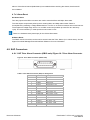
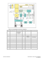
5.4. Fan Tray Block Diagram
Figure 14: Fan Tray Block Diagram
Document CC08100
FlexChassis™ ATCA 12U (14-Slot) DC
User Manual
Table 10: Fan Tray Backplane Connector pin assignment
Pin #
Signal
Description
Pin #
1
NSEAT
Seated Signal for
IPM Controller,
grounded on
Backplane
13
2
3
Signal
Description
14
SGND
Shelf Ground
15
4
16
GND (Fan
Presence)
Presence Signal for
Shelf Manager
5
17
HA0
Hardware Address
6
SCL_A
IPMB-A Clock
18
HA1
Hardware Address
7
SCL_B
IPMB-B Clock
19
HA2
Hardware Address
8
GND
Logic Ground
20
HA3
Hardware Address
21
GND
Logic Ground
GND
Logic Ground
22
SDA_A
IPMB-A Data
11
23
SDA_B
IPMB-B Data
12
24
GND
Logic Ground
9
10
BLADE1
-48V_A
-48 VDC Feed A
BLADE3
-48V_B
-48 VDC Feed B
BLADE2
VRTN_A
RTN Feed A
BLADE4
VRTN_B
RTN Feed B
Document CC08100
FlexChassis™ ATCA 12U (14-Slot) DC
User Manual
5.5. Fan Tray Signals
The Fan Tray provides signals for:
o
Voltage monitoring
o
Status of the Hot Swap Controller
o
Status of the 12 V DC/DC converter
o
Fan Speed
o
Temperature
These signals are controlled by the IPM Controller devices on the Fan Tray PCB. The Shelf Manager has access
to these signals via IPMB.
Table 11: Fan Tray Sensors
Sensor
Name
Description
Sensor
#
Normal
Thresholds
Lower
Critical
Hot Swap
M State
Information
0
Lower
Non-Criti-
Lower
Non-
Upper
Non-Criti-
cal
Recover
able
cal
M4
M1, M2, M3, M5, M6, M7
Upper
Critical
Upper
Non
Recover
able
IPMB
Physical
IPMB
Physical
1
+3.3V
+3.3 V
12
3.3 V
+2.97
+3.135
2.91
+3.465
+3.63
3.7
+5.0V
+5 V
13
5.0 V
+4.5
+4.75
4.4
+5.25
+5.5
5.6
+12.0V
+12 V
14
12.0 V
+9
+10
8.03
+13.5
+14.5
15.52
15
25
N/A
N/A
N/A
61.34
67.55
75.83
LM60 Temp
Temperature
Sensor
Fan 1
RPM
2
On
600
Fan 2
RPM
3
On
600
Fan 3
RPM
4
On
600
Fan 4
RPM
5
On
600
8
Asserted
9
Asserted
RTN Fuse A
10
Asserted
RTN Fuse B
11
Asserted
-48V fuse A
-48V fuse B
-48V rtn
fuse A
-48V rtn
fuse B
-48 V Fuse
A
-48 V Fuse
B
5.6. Fan Tray Temperature Sensor
The temperature sensors (LM75) in the Fan Trays measure the input and exhaust temperatures of the Shelf.
5.7. Fan Tray Connectors and Indicators
The front panel includes the following indicators:
Document CC08100
FlexChassis™ ATCA 12U (14-Slot) DC
User Manual
o
Green LED – “In-Service”
o
Red LED – “Out of Service”
o
Blue LED – “Hot-Swap”
The Hot-Swap switch indicates to the Shelf Managers that the Fan Tray is about to be removed. Its use is optional,
but it is provided so that service personnel can be trained to look for a blue LED to be illuminated on any active
component before removing it from the system. Once the operator releases the Hot-Swap switch, the Shelf
Manager is informed of the pending extraction. When the Shelf Manager feels it is “safe” to remove the Fan Tray,
the blue Hot-Swap LED illuminates solid.
Table 12: LEDs on Fan Tray front panel
Color
Description
Status
Condition
Green
In-Service LED
Off
Solid Green
Fan Tray is inactive
Normal Operation
Out-of-service LED
Off
Solid Red
No error
Error condition
Warning LED
Solid Amber
{not used}
Hot Swap LED
Off
Long blink
Short blink
Solid blue
Fan Tray is active
Request for activation
Request for deactivation
Fan Tray is inactive
Red / Amber
Blue
5.8. Fan Tray IPMB Addresses
Geographic address pins (HA0, HA1, HA2, HA3) at the Fan Tray Backplane connector determine the hardware
addresses of the devices.
Table 13: Fan Tray IPMB Addresses
Fan Tray left
0x2E (Hardware)
0x5C (IPMB)
Fan Tray middle
0x2D (Hardware)
0x5A (IPMB)
Fan Tray right
0x2C (Hardware)
0x58 (IPMB)
5.9. Redundancy
The fan tray has been designed to maximize redundancy within a single fan tray.
o Power draw from A & B feeds with lines individually fused.
o The control circuit is designed so that if the management circuitry does not provide the proper control
signals, the fans default to full speed.
o When the fan tray is first installed in the system, the fans spin at full speed.
o The fan tray has redundant IPMB connections for better management communication reliability.
o The system is designed to run indefinitely with any single fan failure. The circuitry on the controller
board monitors the speed of each fan. When one fan fails, all other fans are increased to full speed.
The fan tray has sufficient cooling capacity to keep the chassis cooled with a single fan failure. The
hybrid serial parallel cooling scheme ensures that the airflow path within each slot is not substantially
affected with a fan failure.
Document CC08100
FlexChassis™ ATCA 12U (14-Slot) DC
User Manual
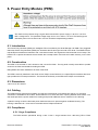
6. Power Entry Module (PEM)
The Shelf can be powered using a regular telecommunication power supply of -48 VDC / -60 VDC
with a voltage return. The specified voltage range is from -40.5 VDC to -72 VDC.The Shelf supports
redundant power sources but the two sources should be independently powered.
6.1. Introduction
The Power Entry Modules (PEMs) are intelligent FRUs controlled by the Shelf Manager via IPMB. Two pluggable
redundant Power Entry Modules (PEMs) are located at the left and right rear side of the Shelf. The PEMs have an
Injector/Ejector handle that interfaces with a mechanical switch and signals the IPM Controller for hot-swap. The
handle has a captive thumbscrew that activates the hot-swap switch and locks the handle securely on the front
panel.
6.2. Construction
The PEM is constructed of .060” aluminum with a chem-film finish. The top panel is easily removable to provide
access to the fuses and headers boarding the PEM.
EMI gaskets have been installed to all sides of the PEM.
The PEM is securely attached to the Shelf via two Phillips screw fasteners. An Injector/Ejector handle at the lower
right provides the hot swap mechanism. The Handle locks directly to the PEM via a Phillips screw fastener.
6.3. Dimensions
3.00”H X 7.5”W X 8.00”D
6.4. Cabling
The PEM terminals meet the accessibility and spacing requirements of IEC 60950 Sub clause 2. A dual stud
connection is available for each cable. These studs are ¼ in. studs with 5/8 in. spacing between stud centers. The
dual studs prevent the power cables from rotating and provide additional secure contacts for the cable lug.
A plastic housing covers the dual stud power feeds and returns to prevent against accidental shorting. The
housing is attached via 1 screw and is removable with a Philips screwdriver.
6.5. Compliance
6.5.1. Surge Compliance
The PEM remains operational during a 500 V 8/20 s surge transient from -48V/-48V_RTN to Earth
Document CC08100
FlexChassis™ ATCA 12U (14-Slot) DC
User Manual
ground, as defined in EN61000-4-5 and provides protection for the shelf against EN61000-4-5 surge
transients. The PEM reduces the EN61000-4-5 surge transients to under -100V for a maximum duration
of 10 s, and under -200V for a maximum duration of 5 s.
6.5.2. EFT Compliance
The PEM remains operational during a 500V 5/50ns EFT transient from -48V/-48V_RTN to Earth ground
as defined in EN61000-4-4 and provides protection for the shelf against EN61000-4-4 EFT transients.
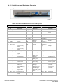
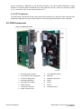
6.6. PEM Components
Figure 15: PEM Components
12707803
Document CC08100
1
Hot Swap Switch Access
9
Circuit Breaker Switch
2
Out Of Service LED (red/amber)
10
EMI Filter
3
In Service LED (green)
11
Backplane Connector
4
Hot Swap LED (blue)
12
Fan#1
5
Injector/Ejector Handle
13
Fan#2
6
VRTN Terminal
14
Fan#3
7
-48/-60 VDC Terminal
15
Hot Swap Switch
8
Power Terminal cover
FlexChassis™ ATCA 12U (14-Slot) DC
User Manual
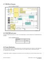
6.7. PEM Block Diagram
Figure 16: PEM Block Diagram
12706918
6.8. PEM IPMB addresses
Geographic address pins (HA0, HA1, HA2) on the PEM Backplane connector determine the IPMB addresses of
the PEM.
Table 14: PEM IPMB addresses
PEM Location
PEM B (Right, view from
front)
0x66
PEM A (Left, view from front)
0x68
6.9. Power Distribution
The power distribution within the Shelf originates from each PEM and powers all the blades, the Shelf Managers,
the Fan Trays and the SAP. For maximum fault tolerance, the two PEMs should be independently powered
by a separate Feed A and Feed B.
A single PEM is capable of supplying the 200 watts of power to each blade slot and the necessary power for the
Document CC08100
FlexChassis™ ATCA 12U (14-Slot) DC
User Manual
Fan Trays and system management.
If two PEMs are in service, each PEM is hot-swappable after removing the power input cables from the PEM.
The PEM has an on-board DC-DC converter to change -48 V to 12 V / 5V / 3.3 V to power the IPM controller and
other on-board devices.
The 12 V and the 3.3 V feeds are also routed to the Backplane connector.
- The 12 V feed is routed to the other PEM as backup power for the IPM controller. This configuration allows the
Shelf Manager to communicate with both PEMs even if power is lost to one PEM.
- The 3.3 V feed is routed to the CDM connector on the Backplane to provide power to the Shelf SEEPROM.
6.10. Specification for the power connection cables
Required wire size:
Diameter 10 mm² resp. AWG8
max. length 2.5 to 3.0 m
suitable for 40 A at 50 °C ambient temperature.
6.11. PEM Signals
The PEM provides signals for:
o
Voltage monitoring
o
Status of the DC/DC converter
o
Fuse Monitoring
o
Temperature
These signals are controlled by the IPM Controller devices on the PEM PCB. The Shelf Manager has access to
these signals via IPM-Bus.
Table 15: PEM Sensors
Sensor
Name
Description
Sensor
#
Normal
Thresholds
Lower
Critical
Hot Swap
FRU State
Information
0
ShelfFRU
HotSwap
FRU State
Information
1
Version
change
IPMB
Physical
+3.3V
+5.0V
+12.0V
fuse
FS11
Version
change
IPMB bus
state
Voltage
Sensor
Voltage
Sensor
Voltage
Sensor
Fuse
Lower
Non-Recoverable
M4
Upper
Non-Critical
Upper
Critical
Upper
Non-Recoverable
M1, M2, M3, M5, M6, M7
M4
M1, M2, M3, M5, M6, M7
2
3
4
3.3 V
+2.97
+3.135
2.9
+3.465
+3.63
3.70
5
5.0 V
+4.5
+4.75
+4.4
+5.25
+5.5
+5.7
6
12.0V
+9.0
+9.4
+8.5
+12.6
+13.2
+13.5
7
Asserted
Fuse
8
Asserted
Fuse
9
Asserted
Fuse
10
Asserted
Document CC08100
Lower
Non-Critical
Asserted
Deasserted
FlexChassis™ ATCA 12U (14-Slot) DC
User Manual
Air Filter
DS75
Temp
-48.0V #1
-48.0V #2
-48.0V #3
-48.0V #4
Filter
Presence
11
Temperature
Sensor
12
Voltage
Sensor
Voltage
Sensor
Voltage
Sensor
Voltage
Sensor
Device
present
Device present
Device Removed / Device Absent
N/A
N/A
N/A
60
67
80
13
-48.0 V
-72
-60
-73
-40
-36
-35
14
-48.0 V
-72
-60
-73
-40
-36
-35
15
-48.0 V
-72
-60
-73
-40
-36
-35
16
-48.0 V
-72
-60
-73
-40
-36
-35
6.12. PEM Connectors and Indicators
The front panel includes the following indicators:
o
Green LED – “In-Service”
o
Bicolor Red and Amber LED – “Out of Service”
o
Blue LED – “Hot-Swap”
The PEMs have an Injector/Ejector handle that interfaces with a mechanical switch and signals the IPM Controller
for hot-swap. Once the operator opens the handle, the switch is released and the Shelf Manager is informed of
the pending extraction. When the Shelf Manager feels it is “safe” to remove the PEM, the blue Hot-Swap LED
illuminates solid.
Table 16: LEDs on PEM front panel
Color
Description
Status
Condition
Green
In-Service LED
Off
PEM is inactive
Red / Amber
Out-of-service LED
Solid Green
Off Solid Red
Warning LED
Solid Amber
Normal Operation
No error
Error condition
-48Vdc not connected
Hot Swap LED
Off
Long blink
Short blink
Solid blue
PEM is active
Request for activation
Request for deactivation
PEM is inactive
Blue
6.13. PEM Connector Pin Assignment
Table 17: PEM Connector pin assignment
Pin #
Signal
A1
-
A2
A3
Pin #
Signal
Description
{no connection}
C1
-
{no connection}
PROM_SDA
Local I2C data
C2
HA1
PROM_SCL
Local I2C clock
C3
FFP
Hardware
Address line 1
Fan Filter
presence signal
12V
C4
Chassis ground
C5
VCC3
3.3 volts
C6
GND
Digital ground
A4
P12V_Y2
A5
SHELF_GND
A6
Document CC08100
Description
Pin #
Signal
Description
Blade
A1
M48VRTN_1
-48V return
Blade
A2
M48VRTN_2
-48V return
Blade
A3
M48VRTN_3
-48V return
FlexChassis™ ATCA 12U (14-Slot) DC
User Manual
B1
-
{no connection}
D1
-
{no connection}
Blade
A4
M48VRTN_4
-48V return
B2
HA2
D2
SCL-A
IPMB-A clock
-48 volts
HA0
D3
SDA_A
IPMB-A data
Blade
B1
Blade
B2
M48V_1
B3
Hardware
Address line 2
Hardware
Address line 0
M48V_2
-48 volts
D4
SCL_B
IPMB-B clock
M48V_3
-48 volts
M48V_4
-48 volts
B4
B5
VCC3
3.3 volts
D5
SDA_B
IPMB-B data
B6
GND
Digital ground
D6
-
{no connection}
Document CC08100
Blade
B3
Blade
B4
FlexChassis™ ATCA 12U (14-Slot) DC
User Manual
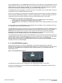
7. Thermals
The ATCA 12U, 14-Slot FlexChassis incorporates a patented Hybrid Serial Parallel (HSP) cooling architecture.
HSP takes advantage of both the fan laws below while best utilizing the available space in a 12U shelf.
Fans in Parallel Law: Flow rates are additive while pressure remains that of a single fan.
Fans in Series Law: Pressures are additive while flow rate remains that of a single fan.
The system provides cooling for the front card cage, and rear card cage. Maximum air volume is achieved with a
convex intake area located at the lower front of the Shelf. Air is exhausted through a Hexcel honeycomb bezel
with 97% open area and low impedance. Design is optimized for beyond 200W/board and is Fault Tolerant using
the HSP fan arrangement scheme that provides uninterrupted cooling.
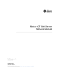
Figure 17: General airflow path for the 12U 14-slot ATCA Shelf
From the shelf front view, the fans are staggered in each fan module thereby achieving a parallel configuration.
From the shelf side view, the fans are placed in a serial configuration. This HSP combination exploits the best of
both fan laws; high flow rates and high pressure. HSP has many other advantages such as superior fault
tolerance and uniform airflow distribution.
HSP is fully compliant with PICMG section 5.1 because the airflow is front to rear and bottom to top. This
requirement ensures that heated exhaust air from a lower shelf in a frame does not impose heated air into the
shelf above it.
Document CC08100
FlexChassis™ ATCA 12U (14-Slot) DC
User Manual
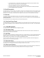
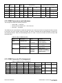
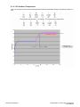
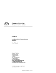
7.1. Typical Airflow Velocities through the slots
Figure 18: Front slot Air Velocities
Figure19: Rear slot Air Velocities
Document CC08100
FlexChassis™ ATCA 12U (14-Slot) DC
User Manual
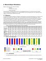
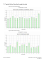
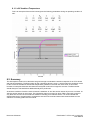
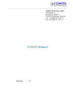
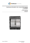
7.2. Thermal Power Dissipation at Various ∆T
Figure 20 shows the approximate cooling capabilities of the Shelf per slot based on different temperature
increases across the board with standard air. For example, with a 15C rise, 310W could be achieved on an ATCA
board.
Figure 20: Thermal Power Dissipation at Various ∆T
7.3. Fan Failure Mode
The HSP cooling architecture was designed with a fan failure in mind. HSP allows air to flow through and around
a locked fan. In addition the entire fan module serves as an intake for air flow. If one of the four fans in a fan
module fails the worst case reduction in velocity or flow rate is less than 15%. The shelf can operate indefinitely
with a fan failure at low operating temperatures.
Document CC08100
FlexChassis™ ATCA 12U (14-Slot) DC
User Manual
8. Service Interval
The purpose of this is to develop an analytical model to estimate the transient response of a typical ATCA blade
and heat sink assembly for various field service events. An example of a field service event would be the
replacement of a fan tray while the system is operational. A service interval is defined as the allowable time a
technician has to replace a fan tray without overheating the system. Several simplifications and assumptions must
be made and are listed below:
o
o
o
o
o
o
Temperature gradients in the heat sink are negligible. (Good assumption for heat sinks with high
efficiency fins and base plates of high thermal conductivity). The biot number must be lower than
0.1.
Thermal mass of heat sink is much larger than heat source/processor. Good assumption for large
heat sinks.
No heat loss due to radiation. Good assumption for case temperature below 100C and high flow
rates.
All the heat flows from the source/processor to the heat sink. This ignores heat transfer to the
board. This is a worst case assumption.
Values for heat sink thermal resistance and mass must be known from experimentation,
simulation or a catalog for various airflow rates.
No preheated air upstream of heat sink. Good assumption for heat sinks on the leading edge of
card.
8.1. Calculations
Document CC08100
FlexChassis™ ATCA 12U (14-Slot) DC
User Manual
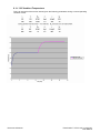
8.1.1. 25C Ambient Temperature
This is an example of the service interval given the following parameters during a normal operating
condition of 25C.
Document CC08100
FlexChassis™ ATCA 12U (14-Slot) DC
User Manual
8.1.2. 35C Ambient Temperature
This is an example of the service interval given the following parameters during an operating condition of
35C.
Document CC08100
FlexChassis™ ATCA 12U (14-Slot) DC
User Manual
8.1.3. 40C Ambient Temperature
This is an example of the service interval given the following parameters during an operating condition of
40C.
8.2. Summary
The assumptions made in this calculation are good enough to estimate the transient response of an ATCA board
and heat sink assembly. The Biot number for the calculations above is near 0.1 which means the analytical model
is valid. Previous simulations showed that temperature gradients in the heat sink were small. As flow rates
increase or base plate thickness decreases this analytical model will no longer be accurate. The Biot number
should always be checked before additional analysis is performed.
At ambient conditions of 25C the service interval is indefinite. At 35C the service interval is just over 3 minutes. At
40C the service interval is one minute. This calculation does not account for which FRU is removed, however it
only takes into account the new heat sink resistance resulting from reduced airflow. It is recommended that
experimental work to be performed to evaluate the actual ATCA board and heat sink thermal resistance in the
chassis to accurately predict service interval.
Document CC08100
FlexChassis™ ATCA 12U (14-Slot) DC
User Manual
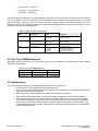
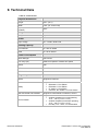
9. Technical Data
Table 18: Technical Data
Physical Dimensions
Height
20.97” (12 U)
Width
17.66” (19” rack mount)
Depth (with PEM Covers and
handles)
18.53”
Weight
Weight
66 pounds
Power
Input voltage
40 – 72VDC, Dual Feed
Cooling Capacity
Front Boards
min. 200 W / Board
RTM
min. 25 W / Board
Power Consumption
Shelf Manager
10W / Board
Fan Trays (x3)
390W at full speed or 180W at low speed
DSAP
10W
PEMs
3W / PEM
EEPROM Board
1W
Regulatory
RoHS
Designed to meet 6/6
Safety
Designed to meet:
• IEC60950-1, First Edition
• EN 60950-1, First Edition
• UL 60950-1, First Edition
• CSA 22.2, No. 60950-1-03, First Edition
EMI Conducted and Radiated
Designed to meet EN55011/CISPR22, Class A
Environmental
Designed to meet:
• Ambient temperature normal operating
+5°C…+45°C (41°F to 113°F)
• Ambient temperature transient operating
+5°C…+55°C (41°F to 131°F)
• Humidity +5%...+85%, no condensation
Document CC08100
FlexChassis™ ATCA 12U (14-Slot) DC
User Manual